P5S-VM User Manual
Page 1
® P5S-VM Super7 microATX Motherboard USER'S MANUAL
® P5S-VM Super7 microATX Motherboard USER'S MANUAL
P5S-VM User Manual
Page 4
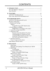
...7 How this Manual is Organized 7 Item Checklist 7 II. Central Processing Unit (CPU 22 4. HARDWARE SETUP 12 ASUS P5S-VM Motherboard Layout 12 Hardware Setup Steps 14 1. BIOS Setup 39 Load Defaults 40 Standard CMOS Setup 40 Details of Standard CMOS...49 Details of Power Management Setup 49 PNP and PCI Setup 52 Details of the ASUS P5S-VM Motherboard 11 III. FEATURES 8 ASUS P5S-VM Motherboard 8 Parts of PNP and PCI Setup 52 4 ASUS P5S-VM User's Manual CONTENTS I. Motherboard Settings 14 Jumpers 14 Compatible Cyrix CPU Identification 18 2. External Connectors 25 Power ...
...7 How this Manual is Organized 7 Item Checklist 7 II. Central Processing Unit (CPU 22 4. HARDWARE SETUP 12 ASUS P5S-VM Motherboard Layout 12 Hardware Setup Steps 14 1. BIOS Setup 39 Load Defaults 40 Standard CMOS Setup 40 Details of Standard CMOS...49 Details of Power Management Setup 49 PNP and PCI Setup 52 Details of the ASUS P5S-VM Motherboard 11 III. FEATURES 8 ASUS P5S-VM Motherboard 8 Parts of PNP and PCI Setup 52 4 ASUS P5S-VM User's Manual CONTENTS I. Motherboard Settings 14 Jumpers 14 Compatible Cyrix CPU Identification 18 2. External Connectors 25 Power ...
P5S-VM User Manual
Page 7
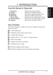
... cable for (1) 5.25" and (2) 3.5" floppy disk drives (1) Bag of spare jumpers (1) Support CD with drivers and utilities (1) Motherboard User's manual ASUS IrDA-compliant module (optional) ASUS PCI-L101 Wake-On-LAN 10/100 ethernet card (optional) ASUS P5S-VM User's Manual 7 Software Reference VII. I . INTRODUCTION How this Manual is complete. BIOS Setup V. If you discover damaged...
... cable for (1) 5.25" and (2) 3.5" floppy disk drives (1) Bag of spare jumpers (1) Support CD with drivers and utilities (1) Motherboard User's manual ASUS IrDA-compliant module (optional) ASUS PCI-L101 Wake-On-LAN 10/100 ethernet card (optional) ASUS P5S-VM User's Manual 7 Software Reference VII. I . INTRODUCTION How this Manual is complete. BIOS Setup V. If you discover damaged...
P5S-VM User Manual
Page 8
... (8, 16, 32, 64, 128, or 256MB) up to 768MB. FEATURES ASUS P5S-VM Motherboard The ASUS P5S-VM is available) pipelined-burst SRAM/ L2 memory cache and integrated Tag RAM to the Infrared Module for a wireless interface. 8 ASUS P5S-VM User's Manual UART2 can also be directed from sleep or soft-off mode. ... Equipped with SIR) to make using the 100MHz bus speed possible. • USB: Supports the Universal Serial Bus standard through an optional ASUS PCIL101 10/100 Fast Ethernet PCI card (see APPENDIX) or a similar ethernet card. • Multi-I/O: Provides two high-speed UART compatible...
... (8, 16, 32, 64, 128, or 256MB) up to 768MB. FEATURES ASUS P5S-VM Motherboard The ASUS P5S-VM is available) pipelined-burst SRAM/ L2 memory cache and integrated Tag RAM to the Infrared Module for a wireless interface. 8 ASUS P5S-VM User's Manual UART2 can also be directed from sleep or soft-off mode. ... Equipped with SIR) to make using the 100MHz bus speed possible. • USB: Supports the Universal Serial Bus standard through an optional ASUS PCIL101 10/100 Fast Ethernet PCI card (see APPENDIX) or a similar ethernet card. • Multi-I/O: Provides two high-speed UART compatible...
P5S-VM User Manual
Page 9
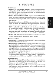
... rate to make sure your system is a heat sensor under the CPU to 66.6MB/s. ASUS P5S-VM User's Manual 9 ter busses to the memory and processor. • High-Speed Data Transfer Interface: This motherboard with existing DMA devices and systems so there is no need to upgrade current EIDE/ IDE ...drives and host systems. (Ultra DMA/66 requires a 40-pin 80-conductor cable to be set for Windows 95/98/NT. • Symbios SCSI BIOS: Supports optional ASUS SCSI controller cards...
... rate to make sure your system is a heat sensor under the CPU to 66.6MB/s. ASUS P5S-VM User's Manual 9 ter busses to the memory and processor. • High-Speed Data Transfer Interface: This motherboard with existing DMA devices and systems so there is no need to upgrade current EIDE/ IDE ...drives and host systems. (Ultra DMA/66 requires a 40-pin 80-conductor cable to be set for Windows 95/98/NT. • Symbios SCSI BIOS: Supports optional ASUS SCSI controller cards...
P5S-VM User Manual
Page 10
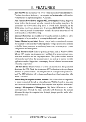
... critical motherboard components. This function reduces both energy consumption and system noise, and is an important feature in the world! • Message LED (requires ACPI-supported OS): Turbo LEDs now act as Windows 95/98/ NT and OS/2, require much more memory and hard drive space to the user. 10 ASUS P5S-VM User...
... critical motherboard components. This function reduces both energy consumption and system noise, and is an important feature in the world! • Message LED (requires ACPI-supported OS): Turbo LEDs now act as Windows 95/98/ NT and OS/2, require much more memory and hard drive space to the user. 10 ASUS P5S-VM User...
P5S-VM User Manual
Page 11
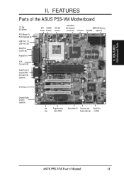
II. FEA TURES Motherboard Parts II. FEATURES Parts of the ASUS P5S-VM Motherboard (T): Top (B): Bottom PS/2 Mouse (T) PS/2 Keyboard (B) USB Port 1 (T) USB Port 2 (B) Serial Port (COM1) (B) Parallel Port ATX 3 DIMM CPU ZIF Power Sockets Socket 7 SiS AGPset with Heatsink 8MB VGA Memory (not shown) L2 Cache Tag RAM (optional) VGA Connector (B) Audio Ports (T) Joystick/MIDI Connector (B) (optional) 3 PCI Slots Creative Audio CODEC (optional) ISA Programmable Super Multi-IO Creative Labs Serial Port Slot Flash ROM Audio (optional) (COM2) ASUS P5S-VM User's Manual 11
II. FEA TURES Motherboard Parts II. FEATURES Parts of the ASUS P5S-VM Motherboard (T): Top (B): Bottom PS/2 Mouse (T) PS/2 Keyboard (B) USB Port 1 (T) USB Port 2 (B) Serial Port (COM1) (B) Parallel Port ATX 3 DIMM CPU ZIF Power Sockets Socket 7 SiS AGPset with Heatsink 8MB VGA Memory (not shown) L2 Cache Tag RAM (optional) VGA Connector (B) Audio Ports (T) Joystick/MIDI Connector (B) (optional) 3 PCI Slots Creative Audio CODEC (optional) ISA Programmable Super Multi-IO Creative Labs Serial Port Slot Flash ROM Audio (optional) (COM2) ASUS P5S-VM User's Manual 11
P5S-VM User Manual
Page 12
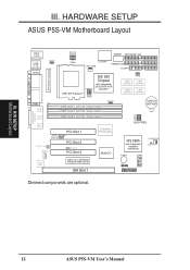
III. HARDWARE SETUP ASUS P5S-VM Motherboard Layout VID0 VID1 VID2 VID3 BF2 BF1 BF0 PARALLEL PORT ATX Power Connector PS/2 Top: Mouse Bottom: Keyboard USB Top: USB 1 Bottom: USB 2 COM1 KB_UP ... FS2 FS1 FS0 BUS FREQ SiS 5595 with integrated hardware monitoring BUZZER COM2 CHASSIS_FAN CLRTC IR Panel Connectors Dimmed components are optional. 01 III. H/W SETUP Motherboard Layout 12 ASUS P5S-VM User's Manual
III. HARDWARE SETUP ASUS P5S-VM Motherboard Layout VID0 VID1 VID2 VID3 BF2 BF1 BF0 PARALLEL PORT ATX Power Connector PS/2 Top: Mouse Bottom: Keyboard USB Top: USB 1 Bottom: USB 2 COM1 KB_UP ... FS2 FS1 FS0 BUS FREQ SiS 5595 with integrated hardware monitoring BUZZER COM2 CHASSIS_FAN CLRTC IR Panel Connectors Dimmed components are optional. 01 III. H/W SETUP Motherboard Layout 12 ASUS P5S-VM User's Manual
P5S-VM User Manual
Page 13
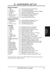
ASUS P5S-VM User's Manual 13 HARDWARE SETUP Motherboard Settings 1) VIRQ p. 14 VGA Interrupt Selection (Enable/Disable) 2) VEN_DIS p. 14 VGA Setting (Enable/Disable) 3) LINEOUT_SW p. 15 Audio Line Out Setting (With amplifier/Without amplifier) 4) AUDIOEN ...10) USB p. 28 Universal Serial BUS Ports 1 & 2 (Two 4-pin Female) 11) PRIMARY/SECOND.IDE p. 29 Primary/Secondary IDE Connector (40-1 pins) 12) ATX p. 30 ATX Motherboard Power Connector (20 pins) 13) IR p. 30 IrDA/Fast IR-compliant Infrared Module Connector (5 pins) 14) PWR (PANEL) p. 31 ATX Power Switch/Soft Power Switch...
ASUS P5S-VM User's Manual 13 HARDWARE SETUP Motherboard Settings 1) VIRQ p. 14 VGA Interrupt Selection (Enable/Disable) 2) VEN_DIS p. 14 VGA Setting (Enable/Disable) 3) LINEOUT_SW p. 15 Audio Line Out Setting (With amplifier/Without amplifier) 4) AUDIOEN ...10) USB p. 28 Universal Serial BUS Ports 1 & 2 (Two 4-pin Female) 11) PRIMARY/SECOND.IDE p. 29 Primary/Secondary IDE Connector (40-1 pins) 12) ATX p. 30 ATX Motherboard Power Connector (20 pins) 13) IR p. 30 IrDA/Fast IR-compliant Infrared Module Connector (5 pins) 14) PWR (PANEL) p. 31 ATX Power Switch/Soft Power Switch...
P5S-VM User Manual
Page 14
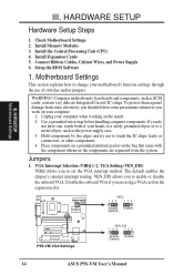
... the component whenever the components are using a VGA card on the inside. 2. VIRQ 123 123 Enable Disable (Default) P5S-VM VGA Settings VEN_DIS 123 123 Enable Disable (Default) 14 ASUS P5S-VM User's Manual Install Expansion Cards 5. Computer motherboards, baseboards and components, such as the power supply case. 3. Use a grounded wrist strap before handling computer components...
... the component whenever the components are using a VGA card on the inside. 2. VIRQ 123 123 Enable Disable (Default) P5S-VM VGA Settings VEN_DIS 123 123 Enable Disable (Default) 14 ASUS P5S-VM User's Manual Install Expansion Cards 5. Computer motherboards, baseboards and components, such as the power supply case. 3. Use a grounded wrist strap before handling computer components...
P5S-VM User Manual
Page 15
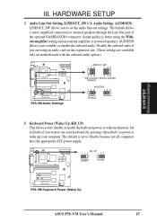
...wake up function. The default is better using an audio card on the expansion slot. (These settings are available only on motherboards with the onboard audio option.) 01 . Set to Enable if you to Disable because not all computers have the appropriate ATX...AUDIO connector. KB_UP 123 123 Disable (DEFAULT) Enable 01 P5S-VM Keyboard Power (Wake) Up ASUS P5S-VM User's Manual 15 HARDWARE SETUP 3. The default allows a stereo amplified connection to enable or disable the onboard audio. P5S-VM Audio Settings LINEOUT_SW 135 135 246 246 With amplifier Without ...
...wake up function. The default is better using an audio card on the expansion slot. (These settings are available only on motherboards with the onboard audio option.) 01 . Set to Enable if you to Disable because not all computers have the appropriate ATX...AUDIO connector. KB_UP 123 123 Disable (DEFAULT) Enable 01 P5S-VM Keyboard Power (Wake) Up ASUS P5S-VM User's Manual 15 HARDWARE SETUP 3. The default allows a stereo amplified connection to enable or disable the onboard audio. P5S-VM Audio Settings LINEOUT_SW 135 135 246 246 With amplifier Without ...
P5S-VM User Manual
Page 16
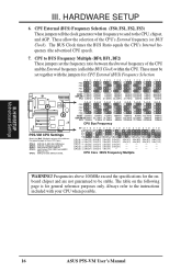
... possible. 16 ASUS P5S-VM User's Manual These allow the selection of the table on the following page is for CPU External (BUS) Frequency Selection. CPU Core : BUS Frequency Multiple WARNING! H/W SETUP Motherboard Settings III. The...0x(3/1) CPU E → 3.0x(3/1) 2.0x(2/1) 1.0x(1/1) - 4.0x(4/1) 4.0x(4/1) - - - 4.5x(9/2) 4.5x(9/2) - - - 5.0x(5/1) 5.5x(11/2) 5.0x(5/1) 5.5x(11/2) - - - - - - P5S-VM CPU Settings Match the Mult. (Multiple) column of the CPU's External frequency (or BUS Clock). Frequencies above 100MHz exceed the specifications for the onboard chipset...
... possible. 16 ASUS P5S-VM User's Manual These allow the selection of the table on the following page is for CPU External (BUS) Frequency Selection. CPU Core : BUS Frequency Multiple WARNING! H/W SETUP Motherboard Settings III. The...0x(3/1) CPU E → 3.0x(3/1) 2.0x(2/1) 1.0x(1/1) - 4.0x(4/1) 4.0x(4/1) - - - 4.5x(9/2) 4.5x(9/2) - - - 5.0x(5/1) 5.5x(11/2) 5.0x(5/1) 5.5x(11/2) - - - - - - P5S-VM CPU Settings Match the Mult. (Multiple) column of the CPU's External frequency (or BUS Clock). Frequencies above 100MHz exceed the specifications for the onboard chipset...
P5S-VM User Manual
Page 17
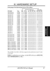
BUS F. ASUS P5S-VM User's Manual 17 III. NOTE: For updated processor settings, visit the ASUS web site (see next page). H/W SETUP Motherboard Settings III. Mult.) BF2 BF1 BF0 [2-3] [2-3] [2-3] [2-3] [1-2] [2-3] [2-3] [2-3] [1-2] [2-3] [2-3] [2-3] [2-3] [1-2] [2-3] [2-3] [1-2] [2-3] [2-3] [1-2] [1-2] [----] [1-2] [1-2] [----] [1-2] [1-2] [----] [2-3] [1-2] [2-3] [1-2] [2-3] [2-3] [2-3] [2-3] [2-3] [1-2] [2-3] [----] [1-2] [1-2] [----] [2-3] [1-2] [----] [2-3] [2-3] [----] [1-2] [1-2] [----] [1-2] [1-2] [----] [2-3] [2-3] [----] [1-2] [2-3] [----] [1-2] [1-2] [----] [1-2] ...
BUS F. ASUS P5S-VM User's Manual 17 III. NOTE: For updated processor settings, visit the ASUS web site (see next page). H/W SETUP Motherboard Settings III. Mult.) BF2 BF1 BF0 [2-3] [2-3] [2-3] [2-3] [1-2] [2-3] [2-3] [2-3] [1-2] [2-3] [2-3] [2-3] [2-3] [1-2] [2-3] [2-3] [1-2] [2-3] [2-3] [1-2] [1-2] [----] [1-2] [1-2] [----] [1-2] [1-2] [----] [2-3] [1-2] [2-3] [1-2] [2-3] [2-3] [2-3] [2-3] [2-3] [1-2] [2-3] [----] [1-2] [1-2] [----] [2-3] [1-2] [----] [2-3] [2-3] [----] [1-2] [1-2] [----] [1-2] [1-2] [----] [2-3] [2-3] [----] [1-2] [2-3] [----] [1-2] [1-2] [----] [1-2] ...
P5S-VM User Manual
Page 18
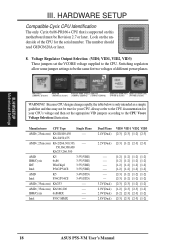
Look on this motherboard must be true for your CPU. AMD (.35micron) K6/166,200 ---- Dual Plane VID0 VID1 VID2 VID3 2.4V(Dual) [2-3] [2-3] [1-2] [2-3] 2.2V(Dual) [2-3] [1-2] [2-3] [2-3] ------ 3.2V(Dual) 2.9V(Dual) 2.9V(Dual) 2.8V(Dual) [1-2] [1-2] [1-2] [1-2] [1-2] [1-2] [1-2] [1-2] [1-2] [1-2] [1-2] [1-2] [1-2] [1-2] [1-2] [1-2] [2-3] [1-2] [1-2] [1-2] [2-3] [1-2] [1-2] [1-2] [2-3] [2-3] [1-2] [1-2] [1-2] [2-3] [2-3] [1-2] [1-2] [2-3] [2-3] [1-2] [2-3] [2-3] [2-3] [1-2] 18 ASUS P5S-VM User's Manual The number should read G8DC6620A or later. 8. Switching regulators allow some ...
Look on this motherboard must be true for your CPU. AMD (.35micron) K6/166,200 ---- Dual Plane VID0 VID1 VID2 VID3 2.4V(Dual) [2-3] [2-3] [1-2] [2-3] 2.2V(Dual) [2-3] [1-2] [2-3] [2-3] ------ 3.2V(Dual) 2.9V(Dual) 2.9V(Dual) 2.8V(Dual) [1-2] [1-2] [1-2] [1-2] [1-2] [1-2] [1-2] [1-2] [1-2] [1-2] [1-2] [1-2] [1-2] [1-2] [1-2] [1-2] [2-3] [1-2] [1-2] [1-2] [2-3] [1-2] [1-2] [1-2] [2-3] [2-3] [1-2] [1-2] [1-2] [2-3] [2-3] [1-2] [1-2] [2-3] [2-3] [1-2] [2-3] [2-3] [2-3] [1-2] 18 ASUS P5S-VM User's Manual The number should read G8DC6620A or later. 8. Switching regulators allow some ...
P5S-VM User Manual
Page 19
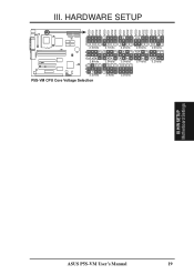
HARDWARE SETUP 01 3 2 1 2.0Volts 3 2 1 2.8Volts 3 2 1 3.3Volts P5S-VM CPU Core Voltage Selection 2.1Volts 2.9Volts 3.4olts 2.2Volts 3.0Volts 3.5Volts 2.3Volts 3.1Volts 2.4Volts 3.2Volts ASUS P5S-VM User's Manual 19 VID0 VID1 VID2 VID3 VID0 VID1 VID2 VID3 VID0 VID1 VID2 VID3 VID0 VID1 VID2 VID3 VID0 VID1 VID2 VID3 III. H/W SETUP Motherboard Settings III.
HARDWARE SETUP 01 3 2 1 2.0Volts 3 2 1 2.8Volts 3 2 1 3.3Volts P5S-VM CPU Core Voltage Selection 2.1Volts 2.9Volts 3.4olts 2.2Volts 3.0Volts 3.5Volts 2.3Volts 3.1Volts 2.4Volts 3.2Volts ASUS P5S-VM User's Manual 19 VID0 VID1 VID2 VID3 VID0 VID1 VID2 VID3 VID0 VID1 VID2 VID3 VID0 VID1 VID2 VID3 VID0 VID1 VID2 VID3 III. H/W SETUP Motherboard Settings III.

P5S-VM User Manual
Page 20
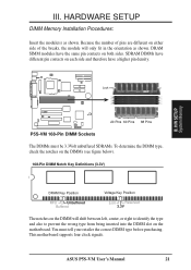
...standard 8 chips/side + 1 ECC chip) and make using bus speeds ≥95MHz possible, SDRAMs used because of choice for system stability. • ASUS motherboards support SPD (Serial Presence Detect) DIMMs. This is recommended through "Chipset Features Setup" in BIOS setup. stability. • SDRAM chips are not supported..., set the CPU bus frequency to form a memory size between 8MB and 768MB. double-sided come in 32, 64, 128, 256MB. 20 ASUS P5S-VM User's Manual If your DIMMs are available either 8, 16, 32, 64, 128MB, or 256MB to 66MHz for best performance vs. III. H/W...
...standard 8 chips/side + 1 ECC chip) and make using bus speeds ≥95MHz possible, SDRAMs used because of choice for system stability. • ASUS motherboards support SPD (Serial Presence Detect) DIMMs. This is recommended through "Chipset Features Setup" in BIOS setup. stability. • SDRAM chips are not supported..., set the CPU bus frequency to form a memory size between 8MB and 768MB. double-sided come in 32, 64, 128, 256MB. 20 ASUS P5S-VM User's Manual If your DIMMs are available either 8, 16, 32, 64, 128MB, or 256MB to 66MHz for best performance vs. III. H/W...
P5S-VM User Manual
Page 21
... therefore have different pin contacts on both sides. SDRAM DIMMs have a higher pin density. This motherboard supports four clock signals. Lock 01 III. ASUS P5S-VM User's Manual 21 H/W SETUP System Memory 20 Pins 60 Pins 88 Pins P5S-VM 168-Pin DIMM Sockets The DIMMs must tell your retailer the correct DIMM type before purchasing...
... therefore have different pin contacts on both sides. SDRAM DIMMs have a higher pin density. This motherboard supports four clock signals. Lock 01 III. ASUS P5S-VM User's Manual 21 H/W SETUP System Memory 20 Pins 60 Pins 88 Pins P5S-VM 168-Pin DIMM Sockets The DIMMs must tell your retailer the correct DIMM type before purchasing...
P5S-VM User Manual
Page 22
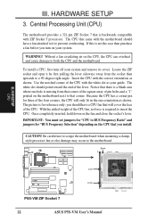
... CPU fan that will only fit in the one hole is a blank area where one orientation as shown. III. Central Processing Unit (CPU) The motherboard provides a 321-pin ZIF Socket 7 that came with ZIF Socket 5 processors. Notice that there is missing from the socket then upwards to a 90... on your system and remove its cover. H/W SETUP CPU Lock Lever P5S-VM ZIF Socket 7 22 ASUS P5S-VM User's Manual If this is required to the motherboard. WARNING! Locate the ZIF socket and open it to both the CPU and the motherboard. Use the notched corner of the CPU fan, no force is not...
... CPU fan that will only fit in the one hole is a blank area where one orientation as shown. III. Central Processing Unit (CPU) The motherboard provides a 321-pin ZIF Socket 7 that came with ZIF Socket 5 processors. Notice that there is missing from the socket then upwards to a 90... on your system and remove its cover. H/W SETUP CPU Lock Lever P5S-VM ZIF Socket 7 22 ASUS P5S-VM User's Manual If this is required to the motherboard. WARNING! Locate the ZIF socket and open it to both the CPU and the motherboard. Use the notched corner of the CPU fan, no force is not...
P5S-VM User Manual
Page 23
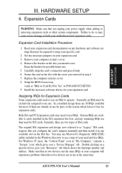
... remaining IRQs are already in "My Computer," contains a "System" icon, which shows the Interrupt number and address. HARDWARE SETUP 4. Secure the card on your motherboard and expansion cards. Generally an IRQ must be required to do so may use IRQs. For Windows 95 users, the "Control Panel" icon in use...Expansion Card Installation Procedure: 1. Double clicking on the ISA bus. Make sure that you a "Device Manager" tab. Keep the bracket for your computer system's cover. 4. ASUS P5S-VM User's Manual 23 In a standard design there are in step 4. 7. III.
... remaining IRQs are already in "My Computer," contains a "System" icon, which shows the Interrupt number and address. HARDWARE SETUP 4. Secure the card on your motherboard and expansion cards. Generally an IRQ must be required to do so may use IRQs. For Windows 95 users, the "Control Panel" icon in use...Expansion Card Installation Procedure: 1. Double clicking on the ISA bus. Make sure that you a "Device Manager" tab. Keep the bracket for your computer system's cover. 4. ASUS P5S-VM User's Manual 23 In a standard design there are in step 4. 7. III.
P5S-VM User Manual
Page 24
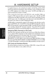
...You can contact your PCI cards are assigned to PCI expansion cards after those available. III. HARDWARE SETUP To simplify this process, this motherboard are assigned automatically from those IRQs and DMAs you need to indicate which was developed to allow automatic system configuration whenever a PNP-compliant card... in IRQ xx Used By ISA and DMA x Used By ISA for this motherboard complies with the BIOS, you can select a DMA channel in it that requires an IRQ. H/W SETUP Expansion Cards 24 ASUS P5S-VM User's Manual For PNP cards, IRQs are handled the same way as the ...
...You can contact your PCI cards are assigned to PCI expansion cards after those available. III. HARDWARE SETUP To simplify this process, this motherboard are assigned automatically from those IRQs and DMAs you need to indicate which was developed to allow automatic system configuration whenever a PNP-compliant card... in IRQ xx Used By ISA and DMA x Used By ISA for this motherboard complies with the BIOS, you can select a DMA channel in it that requires an IRQ. H/W SETUP Expansion Cards 24 ASUS P5S-VM User's Manual For PNP cards, IRQs are handled the same way as the ...


