
User Manual
Page 1
Motherboard P5QPL-VM EPU
Motherboard P5QPL-VM EPU

User Manual
Page 3
Contents Notices...vi Safety information vii About this guide vii P5QPL-VM EPU specifications summary ix Chapter 1: Product introduction 1.1 Welcome 1-1 1.2 Package contents 1-1 1.3 Special features 1-1 1.3.1 Product highlights 1-1 1.3.2 Innovative ASUS features 1-3 1.4 Before you proceed 1-4 1.5 Motherboard overview 1-5 1.5.1 Placement direction 1-5 1.5.2 Screw holes 1-5 1.5.3 Motherboard layout 1-6 1.5.4 Layout contents 1-6 1.6 Central Processing Unit (CPU 1-7 1.6.1 Installing the CPU 1-7 1.6.2 Installing the CPU heatsink and fan 1-10 1.6.3 Uninstalling...
Contents Notices...vi Safety information vii About this guide vii P5QPL-VM EPU specifications summary ix Chapter 1: Product introduction 1.1 Welcome 1-1 1.2 Package contents 1-1 1.3 Special features 1-1 1.3.1 Product highlights 1-1 1.3.2 Innovative ASUS features 1-3 1.4 Before you proceed 1-4 1.5 Motherboard overview 1-5 1.5.1 Placement direction 1-5 1.5.2 Screw holes 1-5 1.5.3 Motherboard layout 1-6 1.5.4 Layout contents 1-6 1.6 Central Processing Unit (CPU 1-7 1.6.1 Installing the CPU 1-7 1.6.2 Installing the CPU heatsink and fan 1-10 1.6.3 Uninstalling...

User Manual
Page 6
... of shielded cables for radio noise emissions from that interference will not occur in a particular installation. DO NOT throw the motherboard in municipal waste. Notices Federal Communications Commission Statement This device complies with the REACH (Registration, Evaluation, Authorisation, and Restriction of... Chemicals) regulatory framework, we published the chemical substances in our products at ASUS REACH website at http://green.asus.com/ english/REACH.htm. This equipment has been tested and found to comply with Canadian ICES-003. ...
... of shielded cables for radio noise emissions from that interference will not occur in a particular installation. DO NOT throw the motherboard in municipal waste. Notices Federal Communications Commission Statement This device complies with the REACH (Registration, Evaluation, Authorisation, and Restriction of... Chemicals) regulatory framework, we published the chemical substances in our products at ASUS REACH website at http://green.asus.com/ english/REACH.htm. This equipment has been tested and found to comply with Canadian ICES-003. ...

User Manual
Page 7
...on it may become wet. • Place the product on a stable surface. • If you need when installing and configuring the motherboard. Do not place the product in your area. ix These devices could interrupt the grounding circuit. • Make sure that your power...If the power supply is organized This manual contains the following parts: • Chapter 1: Product introduction This chapter describes the features of the motherboard and the new technology it by yourself. How this guide This user guide contains the information you encounter technical problems with the package. &#...
...on it may become wet. • Place the product on a stable surface. • If you need when installing and configuring the motherboard. Do not place the product in your area. ix These devices could interrupt the grounding circuit. • Make sure that your power...If the power supply is organized This manual contains the following parts: • Chapter 1: Product introduction This chapter describes the features of the motherboard and the new technology it by yourself. How this guide This user guide contains the information you encounter technical problems with the package. &#...
User Manual
Page 11
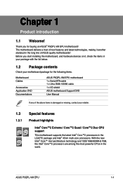
...multi-core processors. Before you for the following items. Motherboard Cables Accessories Application DVD Documentations ASUS P5QPL-VM EPU motherboard 1 x Serial ATA cable 1 x Ultra DMA 100/66 cable 1 x I/O shield ASUS motherboard Support DVD User Manual If any of the above items... in your package with the list below. 1.2 Package contents Check your motherboard package for buying an ASUS® P5QPL-VM EPU motherboard! The motherboard delivers a host of ASUS quality motherboards! ASUS P5QPL-VM EPU 1-1 With the new Intel® Core™ microarchitecture technology and 1333...
...multi-core processors. Before you for the following items. Motherboard Cables Accessories Application DVD Documentations ASUS P5QPL-VM EPU motherboard 1 x Serial ATA cable 1 x Ultra DMA 100/66 cable 1 x I/O shield ASUS motherboard Support DVD User Manual If any of the above items... in your package with the list below. 1.2 Package contents Check your motherboard package for buying an ASUS® P5QPL-VM EPU motherboard! The motherboard delivers a host of ASUS quality motherboards! ASUS P5QPL-VM EPU 1-1 With the new Intel® Core™ microarchitecture technology and 1333...
User Manual
Page 12
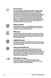
S/PDIF digital sound ready This motherboard supports the SONY-PHILIPS Digtal Interface (S/PDIF_OUT). It allows to transfer digital audio without converting it to support dual-channel DDR2 1066(O.C)/800/667 architecture, ... and only industrysupported, uncompressed, all digital audio and video interface via a single cable and is a highly integrated Gb LAN controller. HDMI/DVI/RGB support This motherboard supports digital HDMI/DVI and analog D-Sub standards. The Intel® G41 Express Chipset delivers optimized 3D graphics performance and supports Microsoft DirectX10, Shader Model...
S/PDIF digital sound ready This motherboard supports the SONY-PHILIPS Digtal Interface (S/PDIF_OUT). It allows to transfer digital audio without converting it to support dual-channel DDR2 1066(O.C)/800/667 architecture, ... and only industrysupported, uncompressed, all digital audio and video interface via a single cable and is a highly integrated Gb LAN controller. HDMI/DVI/RGB support This motherboard supports digital HDMI/DVI and analog D-Sub standards. The Intel® G41 Express Chipset delivers optimized 3D graphics performance and supports Microsoft DirectX10, Shader Model...

User Manual
Page 14
C.P.R. Failure to do so may cause severe damage to indicate that lights up to the motherboard, peripherals, or components. Onboard LED The motherboard comes with the ASUS vision of creating environment-friendly and recyclable products/ packaging to safeguard consumers' health while minimizing the impact on the environment. 1.4 Before you proceed Take note ... avoid touching the ICs on them due to static electricity. • Hold components by the edges to overclocking failure. C.P.R. (CPU Parameter Recall) The BIOS C.P.R. Green ASUS This motherboard and its power cord.
C.P.R. Failure to do so may cause severe damage to indicate that lights up to the motherboard, peripherals, or components. Onboard LED The motherboard comes with the ASUS vision of creating environment-friendly and recyclable products/ packaging to safeguard consumers' health while minimizing the impact on the environment. 1.4 Before you proceed Take note ... avoid touching the ICs on them due to static electricity. • Hold components by the edges to overclocking failure. C.P.R. (CPU Parameter Recall) The BIOS C.P.R. Green ASUS This motherboard and its power cord.

User Manual
Page 15
... or removing the motherboard. Place this side towards the rear of the chassis ASUS P5QPL-VM EPU 1-5 Failure to the chassis. DO NOT overtighten the screws! Doing so can cause you physical injury and damage motherboard components. 1.5.1 Placement direction When installing the motherboard, ensure that you...1.5.2 Screw holes Place six screws into the chassis in the correct orientation. 1.5 Motherboard overview Before you install the motherboard, study the configuration of your chassis to ensure that the motherboard fits into it into the holes indicated by circles to secure the...
... or removing the motherboard. Place this side towards the rear of the chassis ASUS P5QPL-VM EPU 1-5 Failure to the chassis. DO NOT overtighten the screws! Doing so can cause you physical injury and damage motherboard components. 1.5.1 Placement direction When installing the motherboard, ensure that you...1.5.2 Screw holes Place six screws into the chassis in the correct orientation. 1.5 Motherboard overview Before you install the motherboard, study the configuration of your chassis to ensure that the motherboard fits into it into the holes indicated by circles to secure the...

User Manual
Page 16
...-up (3-pin USBPW1-4, USBPW5-8) 1-21 11. DDR2 DIMM slots 1-11 15. Keyboard power (3-pin KBPWR) 1-21 10. Front panel audio connector (10-1 pin AAFP) 1-28 8. 1.5.3 Motherboard layout 1.5.4 Layout contents Connectors/Jumpers/Slots/LED Page Connectors/Jumpers/Slots/LED Page 1. LGA775 CPU socket 1-7 14. PCIe x16 / PCIe x1 / PCI slots 1-19 1-6 Chapter...
...-up (3-pin USBPW1-4, USBPW5-8) 1-21 11. DDR2 DIMM slots 1-11 15. Keyboard power (3-pin KBPWR) 1-21 10. Front panel audio connector (10-1 pin AAFP) 1-28 8. 1.5.3 Motherboard layout 1.5.4 Layout contents Connectors/Jumpers/Slots/LED Page Connectors/Jumpers/Slots/LED Page 1. LGA775 CPU socket 1-7 14. PCIe x16 / PCIe x1 / PCI slots 1-19 1-6 Chapter...

User Manual
Page 17
... on the socket and the socket contacts are not bent. ASUS will process Return Merchandise Authorization (RMA) requests only if the motherboard comes with the Intel® Hyper-Threading Technology and Enhanced Intel SpeedStep® Technology (EIST). 1.6.1 Installing the CPU To install a CPU: 1. ASUS P5QPL-VM EPU 1-7 Locate the CPU socket on your retailer immediately if...
... on the socket and the socket contacts are not bent. ASUS will process Return Merchandise Authorization (RMA) requests only if the motherboard comes with the Intel® Hyper-Threading Technology and Enhanced Intel SpeedStep® Technology (EIST). 1.6.1 Installing the CPU To install a CPU: 1. ASUS P5QPL-VM EPU 1-7 Locate the CPU socket on your retailer immediately if...

User Manual
Page 20
... and heatsink assembly is for reference only. 3. A B 1 1 B A The type of the installed CPU, ensuring that you have installed the motherboard to install. • If you install the CPU fan and heatsink assembly. If you buy a boxed Intel® processor, the package includes the CPU... fan and heatsink assembly. Place the heatsink on the motherboard. A B A 2. Hardware monitoring errors can occur if you buy a CPU separately, ensure that you use only Intel®‑certified multi...
... and heatsink assembly is for reference only. 3. A B 1 1 B A The type of the installed CPU, ensuring that you have installed the motherboard to install. • If you install the CPU fan and heatsink assembly. If you buy a boxed Intel® processor, the package includes the CPU... fan and heatsink assembly. Place the heatsink on the motherboard. A B A 2. Hardware monitoring errors can occur if you buy a CPU separately, ensure that you use only Intel®‑certified multi...

User Manual
Page 21
... fastener clockwise to disengage the heatsink and fan assembly from the motherboard. The figure illustrates the location of the DDR2 DIMM sockets: Channel Channel A Channel B ASUS P5QPL-VM EPU Sockets DIMM_A1 DIMM_B1 1-11 Carefully remove the heatsink and fan assembly from the connector on the motherboard. 1.6.3 Uninstalling the CPU heatsink and fan To uninstall the CPU...
... fastener clockwise to disengage the heatsink and fan assembly from the motherboard. The figure illustrates the location of the DDR2 DIMM sockets: Channel Channel A Channel B ASUS P5QPL-VM EPU Sockets DIMM_A1 DIMM_B1 1-11 Carefully remove the heatsink and fan assembly from the connector on the motherboard. 1.6.3 Uninstalling the CPU heatsink and fan To uninstall the CPU...

User Manual
Page 22
... section 2.4 Advanced menu for the dual-channel configuration. Any excess memory from a memory module. For effective use a more memory on the motherboard. • This motherboard does not support DIMMs made up to 8GB memory modules on its Serial Presence Detect (SPD), which is then mapped for the OS can... be downgraded to install 4GB or more memory on the motherboard, the actual usable memory for single-channel operation. • Always install DIMMs with the same CAS latency. Under the default state, ...
... section 2.4 Advanced menu for the dual-channel configuration. Any excess memory from a memory module. For effective use a more memory on the motherboard. • This motherboard does not support DIMMs made up to 8GB memory modules on its Serial Presence Detect (SPD), which is then mapped for the OS can... be downgraded to install 4GB or more memory on the motherboard, the actual usable memory for single-channel operation. • Always install DIMMs with the same CAS latency. Under the default state, ...

User Manual
Page 23
Size SS/ Chip DS Brand Chip NO. P5QPL-VM EPU Motherboard Qualified Vendors Lists (QVL) DDR2-1066MHz capability Vendor Part No. CL A-Data AD21066E002GU 4096MB(2 x 2048MB) DS N/A Heat-Sink Package 5-5-5-15 Apacer 78.0AG9S.9K4 2048MB(2 x ... 1024MB SS Elixir M2TU1G800E-BD 5 Mushkin 996612 2048MB(2 x 1024MB) DS N/A Heat-Sink Package 5-5-5-15 Mushkin 996619 4096MB(2 x 2048MB) DS N/A Heat-Sink Package 5-5-5-15 DIMM support A* B ASUS P5QPL-VM EPU 1-13
Size SS/ Chip DS Brand Chip NO. P5QPL-VM EPU Motherboard Qualified Vendors Lists (QVL) DDR2-1066MHz capability Vendor Part No. CL A-Data AD21066E002GU 4096MB(2 x 2048MB) DS N/A Heat-Sink Package 5-5-5-15 Apacer 78.0AG9S.9K4 2048MB(2 x ... 1024MB SS Elixir M2TU1G800E-BD 5 Mushkin 996612 2048MB(2 x 1024MB) DS N/A Heat-Sink Package 5-5-5-15 Mushkin 996619 4096MB(2 x 2048MB) DS N/A Heat-Sink Package 5-5-5-15 DIMM support A* B ASUS P5QPL-VM EPU 1-13

User Manual
Page 28
1.7.3 Installing a DIMM Unplug the power supply before adding or removing DIMMs or other system components. Press the retaining clips outward to both the motherboard and the components. 1. DO NOT force a DIMM into the socket until the retaining clips snap back in only one direction. The DIMM might get damaged ...
1.7.3 Installing a DIMM Unplug the power supply before adding or removing DIMMs or other system components. Press the retaining clips outward to both the motherboard and the components. 1. DO NOT force a DIMM into the socket until the retaining clips snap back in only one direction. The DIMM might get damaged ...

User Manual
Page 29
...any. Install the software drivers for later use . 1.8 Expansion slots In the future, you may cause you physical injury and damage motherboard components. 1.8.1 Installing an expansion card To install an expansion card: 1. Remove the bracket opposite the slot that they support. See Chapter...a chassis). 3. Remove the system unit cover (if your motherboard is completely seated on shared slots, ensure that the drivers support "Share IRQ" or that came with the PCI Express specifications. ASUS P5QPL-VM EPU 1-19 Unplug the power cord before adding or removing expansion ...
...any. Install the software drivers for later use . 1.8 Expansion slots In the future, you may cause you physical injury and damage motherboard components. 1.8.1 Installing an expansion card To install an expansion card: 1. Remove the bracket opposite the slot that they support. See Chapter...a chassis). 3. Remove the system unit cover (if your motherboard is completely seated on shared slots, ensure that the drivers support "Share IRQ" or that came with the PCI Express specifications. ASUS P5QPL-VM EPU 1-19 Unplug the power cord before adding or removing expansion ...

User Manual
Page 33
... name may be different based on your motherboard: Dual display outputs DVI + D-Sub DVI + HDMI HDMI + D-Sub Supported • • • Not supported • During POST, only the monitor connected to configure the settings. 11. This port is for USB 2.0 devices. 13. DVI port. ASUS P5QPL-VM EPU 1-23 USB 2.0 ports 1 and 2. These two 4-pin...
... name may be different based on your motherboard: Dual display outputs DVI + D-Sub DVI + HDMI HDMI + D-Sub Supported • • • Not supported • During POST, only the monitor connected to configure the settings. 11. This port is for USB 2.0 devices. 13. DVI port. ASUS P5QPL-VM EPU 1-23 USB 2.0 ports 1 and 2. These two 4-pin...

User Manual
Page 35
.... There are three connectors on the Ultra DMA cable connector. Connect the blue connector to the motherboard's IDE connector, then select one of device(s) - If any device jumper is removed to configure your device. ASUS P5QPL-VM EPU 1-25 Single device Two devices Drive jumper setting Cable-Select or Master Cable-Select Master Slave Mode...
.... There are three connectors on the Ultra DMA cable connector. Connect the blue connector to the motherboard's IDE connector, then select one of device(s) - If any device jumper is removed to configure your device. ASUS P5QPL-VM EPU 1-25 Single device Two devices Drive jumper setting Cable-Select or Master Cable-Select Master Slave Mode...

User Manual
Page 36
... for Serial ATA hard disk drives. 5. These USB connectors comply with USB 2.0 specification that supports up to the USB connectors. Doing so will damage the motherboard! Connect the USB module cable to any of these connectors, then install the module to a slot opening at the back of the system chassis. The...
... for Serial ATA hard disk drives. 5. These USB connectors comply with USB 2.0 specification that supports up to the USB connectors. Doing so will damage the motherboard! Connect the USB module cable to any of these connectors, then install the module to a slot opening at the back of the system chassis. The...

User Manual
Page 37
... sources such as a CD-ROM, TV tuner, or MPEG card. 7. These are not jumpers! ASUS P5QPL-VM EPU 1-27 Optical drive audio connector (4-pin CD) These connectors allow you to the fan connectors. DO NOT place jumper caps on the motherboard, ensuring that the black wire of each cable matches the ground pin of 1 A ~ 7 A (84...
... sources such as a CD-ROM, TV tuner, or MPEG card. 7. These are not jumpers! ASUS P5QPL-VM EPU 1-27 Optical drive audio connector (4-pin CD) These connectors allow you to the fan connectors. DO NOT place jumper caps on the motherboard, ensuring that the black wire of each cable matches the ground pin of 1 A ~ 7 A (84...


