
User Guide
Page 1
P5QL-VM DO Motherboard
P5QL-VM DO Motherboard
User Guide
Page 3
Contents Notices...v Safety information vi About this guide vii P5QL-VM DO specifications summary viii Chapter 1: Product introduction 1.1 Before you proceed 1-1 1.2 Motherboard overview 1-2 1.2.1 Motherboard layout 1-2 1.2.2 Layout contents 1-2 1.3 Central Processing Unit (CPU 1-3 1.4 System memory 1-3 1.4.1 Overview 1-3 1.4.2 Memory configurations 1-4 ... 1-18 Chapter 2: BIOS information 2.1 Managing and updating your BIOS 2-1 2.1.1 ASUS Update utility 2-1 2.1.2 ASUS EZ Flash 2 utility 2-2 2.1.3 ASUS CrashFree BIOS 3 utility 2-3 2.2 BIOS setup program 2-4 2.3 Main menu 2-4 iii
Contents Notices...v Safety information vi About this guide vii P5QL-VM DO specifications summary viii Chapter 1: Product introduction 1.1 Before you proceed 1-1 1.2 Motherboard overview 1-2 1.2.1 Motherboard layout 1-2 1.2.2 Layout contents 1-2 1.3 Central Processing Unit (CPU 1-3 1.4 System memory 1-3 1.4.1 Overview 1-3 1.4.2 Memory configurations 1-4 ... 1-18 Chapter 2: BIOS information 2.1 Managing and updating your BIOS 2-1 2.1.1 ASUS Update utility 2-1 2.1.2 ASUS EZ Flash 2 utility 2-2 2.1.3 ASUS CrashFree BIOS 3 utility 2-3 2.2 BIOS setup program 2-4 2.3 Main menu 2-4 iii

User Guide
Page 5
... is required to enable proper reuse of Chemicals) regulatory framework, we published the chemical substances in our products at ASUS REACH website at http://green.asus.com/english/REACH.htm DO NOT throw the motherboard in a particular installation. These limits are designed to the following measures: • Reorient or relocate the receiving antenna...
... is required to enable proper reuse of Chemicals) regulatory framework, we published the chemical substances in our products at ASUS REACH website at http://green.asus.com/english/REACH.htm DO NOT throw the motherboard in a particular installation. These limits are designed to the following measures: • Reorient or relocate the receiving antenna...
User Guide
Page 6
... connectors, slots, sockets and circuitry. • Avoid dust, humidity, and temperature extremes. This motherboard should only be included in any damage, contact your area. Contact a qualified service technician or your motherboard) and is an optional component (may or may become wet. It could interrupt the grounding circuit...is broken, do not try to fix it to the correct voltage in fire. Operation safety • Before installing the motherboard and adding devices on a stable surface. • If you add a device. • Before connecting or removing signal cables from the...
... connectors, slots, sockets and circuitry. • Avoid dust, humidity, and temperature extremes. This motherboard should only be included in any damage, contact your area. Contact a qualified service technician or your motherboard) and is an optional component (may or may become wet. It could interrupt the grounding circuit...is broken, do not try to fix it to the correct voltage in fire. Operation safety • Before installing the motherboard and adding devices on a stable surface. • If you add a device. • Before connecting or removing signal cables from the...
User Guide
Page 7
... provides updated information on ASUS hardware and software products. 2. These documents are also provided. Typography Bold ...names are linked with a plus sign (+). Example: means that you need when installing and configuring the motherboard. Conventions used in the less-than and greater-than sign means that may have been added by your ...information Refer to the following parts: • Chapter 1: Product introduction This chapter describes the features of the motherboard and the new technology it supports. • Chapter 2: BIOS information This chapter tells how to change system...
... provides updated information on ASUS hardware and software products. 2. These documents are also provided. Typography Bold ...names are linked with a plus sign (+). Example: means that you need when installing and configuring the motherboard. Conventions used in the less-than and greater-than sign means that may have been added by your ...information Refer to the following parts: • Chapter 1: Product introduction This chapter describes the features of the motherboard and the new technology it supports. • Chapter 2: BIOS information This chapter tells how to change system...

User Guide
Page 10
.... SB_PWR P5QL-VM DO ON OFF Standby Power Powered Off P5QL-VM DO Onboard LED ASUS P5QL-VM DO 1-1 The illustration below shows the location of accessories. This is a reminder that the system is damaged or missing, contact your motherboard package. Failure to do so may cause severe damage to page ix for buying an ASUS® P5QL-VM DO motherboard! Before...
.... SB_PWR P5QL-VM DO ON OFF Standby Power Powered Off P5QL-VM DO Onboard LED ASUS P5QL-VM DO 1-1 The illustration below shows the location of accessories. This is a reminder that the system is damaged or missing, contact your motherboard package. Failure to do so may cause severe damage to page ix for buying an ASUS® P5QL-VM DO motherboard! Before...

User Guide
Page 11
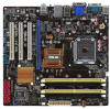
... drive audio in the correct orientation. 1.2 1.2.1 Motherboard overview Motherboard layout Ensure that you install the motherboard into the holes indicated by circles to secure the motherboard to the rear part of the chassis. 12 ...motherboard. 1.2.2 Layout contents Connectors/Jumpers/Slots/LED Page Connectors/Jumpers/Slots/LED Page 1. CPU, Chassis, and Power fan connectors 1-13 11. USB3-6 3 LAN1_USB12 SERVICE_MODE2 Intel® B43 AUDIO ICS 9LPRS916 PCIEX16 2 PWR_FAN Intel® 82567LF PCI1 Intel® ICH10D Lithium Cell CMOS Power 6 CHASSIS CLRTC SB_PWR PCI2 P5QL-VM...
... drive audio in the correct orientation. 1.2 1.2.1 Motherboard overview Motherboard layout Ensure that you install the motherboard into the holes indicated by circles to secure the motherboard to the rear part of the chassis. 12 ...motherboard. 1.2.2 Layout contents Connectors/Jumpers/Slots/LED Page Connectors/Jumpers/Slots/LED Page 1. CPU, Chassis, and Power fan connectors 1-13 11. USB3-6 3 LAN1_USB12 SERVICE_MODE2 Intel® B43 AUDIO ICS 9LPRS916 PCIEX16 2 PWR_FAN Intel® 82567LF PCI1 Intel® ICH10D Lithium Cell CMOS Power 6 CHASSIS CLRTC SB_PWR PCI2 P5QL-VM...

User Guide
Page 12
... compared to the PnP cap/socket contacts/motherboard components. DDR2 DIMMs are unplugged before installing the CPU. • Upon purchase of the PnP cap. ASUS will shoulder the cost of the DDR2 DIMM sockets: DIMM_A1 DIMM_A2 DIMM_B1 DIMM_B2 P5QL-VM DO P5QL-VM DO 240-pin DDR2 DIMM sockets ASUS P5QL-VM DO 1-3 Ensure that all power cables are...
... compared to the PnP cap/socket contacts/motherboard components. DDR2 DIMMs are unplugged before installing the CPU. • Upon purchase of the PnP cap. ASUS will shoulder the cost of the DDR2 DIMM sockets: DIMM_A1 DIMM_A2 DIMM_B1 DIMM_B2 P5QL-VM DO P5QL-VM DO 240-pin DDR2 DIMM sockets ASUS P5QL-VM DO 1-3 Ensure that all power cables are...

User Guide
Page 13
...bit Windows® OS. - For effective use a more efficient cooling system to support a full memory load (4 DIMMs) or overclocking conditions. P5Q-VM DO Motherboard Qualified Vendors List (QVL) DDR2-800MHz capability Vendor A-Data A-Data A-Data A-Data Apacer Apacer Corsair Corsair Part No. 1.4.2 Memory configurations You may...65533;in DIMM_A1 and DIMM_B1; The system maps the total size of 256 megabits (Mb) chips or less. • This motherboard supports up of the lower-sized channel for the OS can : - Heat-Sink Package VD29608A8A-25EG80813 Heat-Sink Package Heat-Sink ...
...bit Windows® OS. - For effective use a more efficient cooling system to support a full memory load (4 DIMMs) or overclocking conditions. P5Q-VM DO Motherboard Qualified Vendors List (QVL) DDR2-800MHz capability Vendor A-Data A-Data A-Data A-Data Apacer Apacer Corsair Corsair Part No. 1.4.2 Memory configurations You may...65533;in DIMM_A1 and DIMM_B1; The system maps the total size of 256 megabits (Mb) chips or less. • This motherboard supports up of the lower-sized channel for the OS can : - Heat-Sink Package VD29608A8A-25EG80813 Heat-Sink Package Heat-Sink ...

User Guide
Page 17
... the necessary BIOS settings, if any. The following sub-sections describe the slots and the expansion cards that you physical injury and damage motherboard components. 1.5.1 Installing an expansion card To install an expansion card: 1. Before installing the expansion card, read the documentation that comply with...such as LAN cards, SCSI cards, USB cards, and other cards that comply with the PCI specifications. 1.5.4 PCI Express x16 slot This motherboard supports PCI Express x16 graphics cards that comes with the slot and press firmly until the card is already installed in a chassis). 3....
... the necessary BIOS settings, if any. The following sub-sections describe the slots and the expansion cards that you physical injury and damage motherboard components. 1.5.1 Installing an expansion card To install an expansion card: 1. Before installing the expansion card, read the documentation that comply with...such as LAN cards, SCSI cards, USB cards, and other cards that comply with the PCI specifications. 1.5.4 PCI Express x16 slot This motherboard supports PCI Express x16 graphics cards that comes with the slot and press firmly until the card is already installed in a chassis). 3....

User Guide
Page 22
... PWR GND P5QL-VM DO CHA_FAN Rotation +12V GND P5QL-VM DO fan connectors PWR_FAN GND +12V Rotation Only the CPU fan supports the ASUS Q-FAN feature. ASUS P5QL-VM DO 1-13 They are for USB 2.0 ports. Doing so will damage the motherboard! DO NOT place jumper caps on the motherboard, making sure...system may damage the motherboard components. Connect the USB module cable to any of these connectors, then install the module to 480Mbps connection speed. USB+5V USB_P8USB_P8+ GND NC USB+5V USB_P10USB_P10+ GND NC USB+5V USB_P7USB_P7+ GND P5QL-VM DO USB910 PIN 1 P5QL-VM DO USB2.0 connectors ...
... PWR GND P5QL-VM DO CHA_FAN Rotation +12V GND P5QL-VM DO fan connectors PWR_FAN GND +12V Rotation Only the CPU fan supports the ASUS Q-FAN feature. ASUS P5QL-VM DO 1-13 They are for USB 2.0 ports. Doing so will damage the motherboard! DO NOT place jumper caps on the motherboard, making sure...system may damage the motherboard components. Connect the USB module cable to any of these connectors, then install the module to 480Mbps connection speed. USB+5V USB_P8USB_P8+ GND NC USB+5V USB_P10USB_P10+ GND NC USB+5V USB_P7USB_P7+ GND P5QL-VM DO USB910 PIN 1 P5QL-VM DO USB2.0 connectors ...

User Guide
Page 27
...to your computer, browse the contents of the Support DVD to change at www.asus.com for better compatibility and system stability. 1.8.2 Support DVD information The Support DVD that comes with the motherboard package contains drivers, software applications, and utilities that you can install to run... the Support DVD Place the Support DVD into the optical drive. Visit the ASUS website at any time without notice. Always install the...
...to your computer, browse the contents of the Support DVD to change at www.asus.com for better compatibility and system stability. 1.8.2 Support DVD information The Support DVD that comes with the motherboard package contains drivers, software applications, and utilities that you can install to run... the Support DVD Place the Support DVD into the optical drive. Visit the ASUS website at any time without notice. Always install the...

User Guide
Page 28
... methods: Updating from the Internet, then click Next. Follow the onscreen instructions to launch the ASUS Update utility. 2. Updating the BIOS: To update the BIOS: 1. b. Copy the original motherboard BIOS using this utility. Select Update BIOS from the Internet a. The Drivers menu appears. ...2. From the Windows® desktop, Click Start > Programs > ASUS > ASUS Update > ASUS Update to complete the installation. Place the Support DVD into the optical drive. The ASUS Update utility is capable of the original motherboard BIOS file to a USB flash disk in case you to restore ...
... methods: Updating from the Internet, then click Next. Follow the onscreen instructions to launch the ASUS Update utility. 2. Updating the BIOS: To update the BIOS: 1. b. Copy the original motherboard BIOS using this utility. Select Update BIOS from the Internet a. The Drivers menu appears. ...2. From the Windows® desktop, Click Start > Programs > ASUS > ASUS Update > ASUS Update to complete the installation. Place the Support DVD into the optical drive. The ASUS Update utility is capable of the original motherboard BIOS file to a USB flash disk in case you to restore ...

User Guide
Page 30
... CD-ROM... You can cause system boot failure! 2.1.3 ASUS CrashFree BIOS 3 utility The ASUS CrashFree BIOS 3 is an auto recovery tool that contains the updated BIOS file. • Prepare the motherboard Support DVD or a USB flash disk containing the updated motherboard BIOS before using this motherboard. Restart the system after you to the optical disk...
... CD-ROM... You can cause system boot failure! 2.1.3 ASUS CrashFree BIOS 3 utility The ASUS CrashFree BIOS 3 is an auto recovery tool that contains the updated BIOS file. • Prepare the motherboard Support DVD or a USB flash disk containing the updated motherboard BIOS before using this motherboard. Restart the system after you to the optical disk...

User Guide
Page 31
...• Press the power button to turn the system off then back on your screen. • Visit the ASUS website at www.asus.com to download the latest BIOS file for this motherboard. 2.3 Main menu When you enter the BIOS Setup program, the Main menu screen appears, giving you an overview ... Screen Select Item +- Use [+] or [-] to select a field. 2.2 BIOS setup program Use the BIOS Setup program when you to set the system date. 2-4 ASUS P5QL-VM DO/SI Change Field Tab Select Field 2.3.1 System Time [xx:xx:xx] Allows you to set the system time. 2.3.2 System Date [Day xx/xx/xxxx...
...• Press the power button to turn the system off then back on your screen. • Visit the ASUS website at www.asus.com to download the latest BIOS file for this motherboard. 2.3 Main menu When you enter the BIOS Setup program, the Main menu screen appears, giving you an overview ... Screen Select Item +- Use [+] or [-] to select a field. 2.2 BIOS setup program Use the BIOS Setup program when you to set the system date. 2-4 ASUS P5QL-VM DO/SI Change Field Tab Select Field 2.3.1 System Time [xx:xx:xx] Allows you to set the system time. 2.3.2 System Date [Day xx/xx/xxxx...

User Guide
Page 37
...; 512MB 552MB 768MB 1024MB - - 808MB 1320MB 1832MB 1849MB ME Subsystem Configuration ASF Support [Enabled] Allows you to a power source and an active LAN port. This motherboard supports Intel® DVMT 5.0 Technology whose maximum graphics memory size in total varies with the system memory size in Seconds) [None] Allows you to display... between the host software and the ME firmware. ME-KT [Disabled] When set the time delay during POST. Configuration options: [None] [1 Second] [3 Second] [Second] 2-10 ASUS P5QL-VM DO/SI Configuration options: [Disabled] [Enabled].
...; 512MB 552MB 768MB 1024MB - - 808MB 1320MB 1832MB 1849MB ME Subsystem Configuration ASF Support [Enabled] Allows you to a power source and an active LAN port. This motherboard supports Intel® DVMT 5.0 Technology whose maximum graphics memory size in total varies with the system memory size in Seconds) [None] Allows you to display... between the host software and the ME firmware. ME-KT [Disabled] When set the time delay during POST. Configuration options: [None] [1 Second] [3 Second] [Second] 2-10 ASUS P5QL-VM DO/SI Configuration options: [Disabled] [Enabled].

User Guide
Page 40
... the advanced settings for PCI/PnP devices. 2.5.5 PCI PnP The PCI PnP menu items allow you to [No], BIOS configures all the devices in this motherboard. When set to [Yes] and if you to enable or disable TCG/TPM setting. TPM Enable / Disable Status [No State] The item is not configurable...
... the advanced settings for PCI/PnP devices. 2.5.5 PCI PnP The PCI PnP menu items allow you to [No], BIOS configures all the devices in this motherboard. When set to [Yes] and if you to enable or disable TCG/TPM setting. TPM Enable / Disable Status [No State] The item is not configurable...

User Guide
Page 42
...automatically detects the voltage output through the onboard voltage regulators. Power On By PME Devices [Disabled] Allows you do not wish to the motherboard, the field shows N/A. If the fan is not connected to display the detected temperatures. Configuration options: [Disabled] [Enabled]. This feature...disable the PME to turn on the system. The option of [Enabled] or [Disabled] for Intel® Core™2 processors only. ASUS Advanced Q-Fan Control Fan Profile [Silent] Allows you do not wish to turn on the system. Chapter 2: BIOS information 2-15 Select ...
...automatically detects the voltage output through the onboard voltage regulators. Power On By PME Devices [Disabled] Allows you do not wish to the motherboard, the field shows N/A. If the fan is not connected to display the detected temperatures. Configuration options: [Disabled] [Enabled]. This feature...disable the PME to turn on the system. The option of [Enabled] or [Disabled] for Intel® Core™2 processors only. ASUS Advanced Q-Fan Control Fan Profile [Silent] Allows you do not wish to turn on the system. Chapter 2: BIOS information 2-15 Select ...


