
User Manual
Page 23
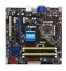
ATX power connectors (24-pin EATXPWR, 4-pin ATX12V) 3. Floppy disk drive connector (34-1 pin FLOPPY) 7. Clear RTC RAM (3-pin CLRTC) 11. System panel connector (20-8 pin PANEL) 12. USB7-10; Front panel audio connector (10-1 pin AAFP) 18. 1.5.2 ... audio connector (4-1 pin SPDIF_OUT) Page 1-30 1-41 1-14 1-19 1-38 1-34 1-37 1-35 1-36 1-28 1-42 1-39 1-9 1-37 1-29 1-40 1-40 1-39 ASUS P5Q-VM 1-11 USB1112) 15. USB1112) 16. DDR2 DIMM slots 5. IDE connector (40-1 pin PRI_EIDE) 9. Chassis intrusion connector (4-1 pin CHASSIS) 13. LGA775 CPU Socket 4. USB connectors ...
ATX power connectors (24-pin EATXPWR, 4-pin ATX12V) 3. Floppy disk drive connector (34-1 pin FLOPPY) 7. Clear RTC RAM (3-pin CLRTC) 11. System panel connector (20-8 pin PANEL) 12. USB7-10; Front panel audio connector (10-1 pin AAFP) 18. 1.5.2 ... audio connector (4-1 pin SPDIF_OUT) Page 1-30 1-41 1-14 1-19 1-38 1-34 1-37 1-35 1-36 1-28 1-42 1-39 1-9 1-37 1-29 1-40 1-40 1-39 ASUS P5Q-VM 1-11 USB1112) 15. USB1112) 16. DDR2 DIMM slots 5. IDE connector (40-1 pin PRI_EIDE) 9. Chassis intrusion connector (4-1 pin CHASSIS) 13. LGA775 CPU Socket 4. USB connectors ...

User Manual
Page 40
... is required to re-enter data. For system failure due to pins 1-2. 3. You must turn ON the computer. 4. The onboard button cell battery powers the RAM data in CMOS. Removing the cap will cause system boot failure! • If the steps above do not need to clear the RTC when the... system hangs due to clear the CMOS RTC RAM data. After the CMOS clearance, reinstall the battery. • You do not help, remove the onboard battery and move the cap back to overclocking, use...
... is required to re-enter data. For system failure due to pins 1-2. 3. You must turn ON the computer. 4. The onboard button cell battery powers the RAM data in CMOS. Removing the cap will cause system boot failure! • If the steps above do not need to clear the RTC when the... system hangs due to clear the CMOS RTC RAM data. After the CMOS clearance, reinstall the battery. • You do not help, remove the onboard battery and move the cap back to overclocking, use...

User Manual
Page 66
...the configuration of the SPI chip. Do this utility. 2.2 BIOS setup program This motherboard supports a programmable firmware chip that the computer can recognize these changes and record them in the CMOS RAM of your computer in the future. Even if you are not prompted to use as... possible. The firmware chip on your screen. • Visit the ASUS website (www.asus.com) to configure your system using the provided utility described in this section are installing a motherboard, reconfiguring...
...the configuration of the SPI chip. Do this utility. 2.2 BIOS setup program This motherboard supports a programmable firmware chip that the computer can recognize these changes and record them in the CMOS RAM of your computer in the future. Even if you are not prompted to use as... possible. The firmware chip on your screen. • Visit the ASUS website (www.asus.com) to configure your system using the provided utility described in this section are installing a motherboard, reconfiguring...

User Manual
Page 93
... information on top of at least six letters and/or numbers, then press . 3. After you have set or change the supervisor password. ASUS P5Q-VM 2-37 again to erase the RTC RAM. After you set a password, this item to set a supervisor password, the other security settings. From the password box, type a password composed of... Installed Change Supervisor Password Change User Password to display the configuration options. If you can clear it by erasing the CMOS Real Time Clock (RTC) RAM.
... information on top of at least six letters and/or numbers, then press . 3. After you have set or change the supervisor password. ASUS P5Q-VM 2-37 again to erase the RTC RAM. After you set a password, this item to set a supervisor password, the other security settings. From the password box, type a password composed of... Installed Change Supervisor Password Change User Password to display the configuration options. If you can clear it by erasing the CMOS Real Time Clock (RTC) RAM.

User Manual
Page 99
...exit this operation. Exit & Discard Changes Select this option only if you do not want to save or discard your changes to the non-volatile RAM. Select one of the parameters on even when the PC is turned off. Select Ok to save changes and exit. Press to save the ...with a message asking if you want to save the changes that you made and restore the previously saved values. ASUS P5Q-VM 2-43 After selecting this option from the legend bar to the CMOS RAM. Select Screen Select Item Enter Go to discard the selections you select this menu or from the Exit menu...
...exit this operation. Exit & Discard Changes Select this option only if you do not want to save or discard your changes to the non-volatile RAM. Select one of the parameters on even when the PC is turned off. Select Ok to save changes and exit. Press to save the ...with a message asking if you want to save the changes that you made and restore the previously saved values. ASUS P5Q-VM 2-43 After selecting this option from the legend bar to the CMOS RAM. Select Screen Select Item Enter Go to discard the selections you select this menu or from the Exit menu...


