
User Manual
Page 31
ok A:\> 當 BIOS DOS 31 Reading flash ..... Version 1.19(ASUS V2.07(03.11.24BB)) Copyright (C) 2002 American Megatrends, Inc. done Write to file...... exe 2 DOS afudos /o[filename filename A:\>afudos /oOLDBIOS1.rom 3. 按下 afudos /oOLDBIOS1.rom AMI Firmware Update Utility - BIOS 2.1 使用 AFUDOS BIOS AFUDOS DOS BIOS BIOS 程式。AFUDOS BIOS BIOS BIOS 程式 BIOS 程式。 1.2MB BIOS 1 AFUDOS 程式(afudos. All rights reserved.
ok A:\> 當 BIOS DOS 31 Reading flash ..... Version 1.19(ASUS V2.07(03.11.24BB)) Copyright (C) 2002 American Megatrends, Inc. done Write to file...... exe 2 DOS afudos /o[filename filename A:\>afudos /oOLDBIOS1.rom 3. 按下 afudos /oOLDBIOS1.rom AMI Firmware Update Utility - BIOS 2.1 使用 AFUDOS BIOS AFUDOS DOS BIOS BIOS 程式。AFUDOS BIOS BIOS BIOS 程式 BIOS 程式。 1.2MB BIOS 1 AFUDOS 程式(afudos. All rights reserved.

User Manual
Page 32
... reserved. Do not turn off power during flash BIOS Reading file ....... Erasing flash ...... 更新 BIOS 程式 AFUDOS BIOS 程式。 1 tw.asus.com BIOS 片中。 BIOS BIOS 2. 將 AFUDOS.EXE BIOS 3 DOS afudos /i[filename filename BIOS 程式。 A:\>afudos /iP5B-VM DO.ROM 4. Version 1.19(ASUS V2.07(03.11.24BB)) Copyright (C) 2002 American...
... reserved. Do not turn off power during flash BIOS Reading file ....... Erasing flash ...... 更新 BIOS 程式 AFUDOS BIOS 程式。 1 tw.asus.com BIOS 片中。 BIOS BIOS 2. 將 AFUDOS.EXE BIOS 3 DOS afudos /i[filename filename BIOS 程式。 A:\>afudos /iP5B-VM DO.ROM 4. Version 1.19(ASUS V2.07(03.11.24BB)) Copyright (C) 2002 American...

User Manual
Page 33
... 程式(AWDFLASH.EXE BIOS AwardBIOS Flash BIOS 程式。 1 http://tw.asus.com BIOS M2N-VM HDMI.bin FAT 32/16 格式的 USB BIOS 2 CD/DVD AwardBIOS Flash BIOS 3 DOS 4. 當 A BIOS 檔案與 AwardBIOS Flash 5 A awdflash 並按下 鍵。 AwardBIOS Flash Utility for ASUS V1.14 (C) Phoenix Technologies Ltd...
... 程式(AWDFLASH.EXE BIOS AwardBIOS Flash BIOS 程式。 1 http://tw.asus.com BIOS M2N-VM HDMI.bin FAT 32/16 格式的 USB BIOS 2 CD/DVD AwardBIOS Flash BIOS 3 DOS 4. 當 A BIOS 檔案與 AwardBIOS Flash 5 A awdflash 並按下 鍵。 AwardBIOS Flash Utility for ASUS V1.14 (C) Phoenix Technologies Ltd...

User Manual
Page 34
... Program: M2A-VM HDMI.bin Programming Flash Memory - All Rights Reserved For C51PV-MCP51-M2A-VM HDMI-00 DATE:04/13/2006 Flash Type - 7 BIOS N BIOS 8 BIOS BIOS AwardBIOS Flash Utility for ASUS V1.14 (C) Phoenix Technologies Ltd. PMC Pm49FL004T LPC/FWH File Name to Continue Write OK F1 Reset No Update Write Fail 34...
... Program: M2A-VM HDMI.bin Programming Flash Memory - All Rights Reserved For C51PV-MCP51-M2A-VM HDMI-00 DATE:04/13/2006 Flash Type - 7 BIOS N BIOS 8 BIOS BIOS AwardBIOS Flash Utility for ASUS V1.14 (C) Phoenix Technologies Ltd. PMC Pm49FL004T LPC/FWH File Name to Continue Write OK F1 Reset No Update Write Fail 34...

User Manual
Page 4
... the OS shut down function 1-46 1.12.2 Using the dual function power switch 1-46 Chapter 2: BIOS setup 2.1 Managing and updating your BIOS 2-2 2.1.1 ASUS Update utility 2-2 2.1.2 Creating a bootable floppy disk 2-5 2.1.3 ASUS EZ Flash 2 utility 2-6 2.1.4 AFUDOS utility 2-7 2.1.5 ASUS CrashFree BIOS 3 utility 2-9 2.2 BIOS setup program 2-10 2.2.1 BIOS menu screen 2-11 2.2.2 Menu bar 2-11 2.2.3 Navigation keys 2-11 2.2.4 Menu items 2-12 2.2.5 Sub-menu...
... the OS shut down function 1-46 1.12.2 Using the dual function power switch 1-46 Chapter 2: BIOS setup 2.1 Managing and updating your BIOS 2-2 2.1.1 ASUS Update utility 2-2 2.1.2 Creating a bootable floppy disk 2-5 2.1.3 ASUS EZ Flash 2 utility 2-6 2.1.4 AFUDOS utility 2-7 2.1.5 ASUS CrashFree BIOS 3 utility 2-9 2.2 BIOS setup program 2-10 2.2.1 BIOS menu screen 2-11 2.2.2 Menu bar 2-11 2.2.3 Navigation keys 2-11 2.2.4 Menu items 2-12 2.2.5 Sub-menu...

User Manual
Page 8
... documentation Your product package may include optional documentation, such as warranty flyers, that you need when installing and configuring the motherboard. viii ASUS websites The ASUS website provides updated information on the motherboard. • Chapter 2: BIOS setup This chapter tells how to the following parts: • Chapter 1: Product introduction This chapter describes the features of...
... documentation Your product package may include optional documentation, such as warranty flyers, that you need when installing and configuring the motherboard. viii ASUS websites The ASUS website provides updated information on the motherboard. • Chapter 2: BIOS setup This chapter tells how to the following parts: • Chapter 1: Product introduction This chapter describes the features of...

User Manual
Page 11
... ASUS Quiet Thermal Solution: - ASUS Fan Xpert ASUS Crystal Sound: - ASUS CrashFree BIOS 3 - ASUS EZ Flash 2 ASUS MyLogo 2™ Precision Tweaker 2: - vChipset (N.B.): 30-step chipset voltage control - ASUS EPU-4 Engine - Profile - ASUS Fanless Design - ASUS O.C. vCPU PLL: 35-step CPU PLL voltage control - P5Q-EM specifications summary ASUS Unique features Other features ASUS Exclusive Overclocking features Rear panel connectors ASUS Power Saving solution: - ASUS Noise Filtering ASUS...
... ASUS Quiet Thermal Solution: - ASUS Fan Xpert ASUS Crystal Sound: - ASUS CrashFree BIOS 3 - ASUS EZ Flash 2 ASUS MyLogo 2™ Precision Tweaker 2: - vChipset (N.B.): 30-step chipset voltage control - ASUS EPU-4 Engine - Profile - ASUS Fanless Design - ASUS O.C. vCPU PLL: 35-step CPU PLL voltage control - P5Q-EM specifications summary ASUS Unique features Other features ASUS Exclusive Overclocking features Rear panel connectors ASUS Power Saving solution: - ASUS Noise Filtering ASUS...

User Manual
Page 12
... P5Q-EM specifications summary Internal connectors BIOS features Manageability Support DVD contents Form factor 3 x USB connectors support 6 additional USB ports 1 x Floppy disk drive connector 1 x IDE connector 6 x SATA connectors 1 x CPU / 1 x Chassis / 1 x Power fan connectors 1 x IEEE1394a connector 1 x COM connector 1 x S/PDIF Out header 1 x Chassis intrusion connector 1 x Front panel audio connector 1 x CD audio in connector 24-pin ATX...
... P5Q-EM specifications summary Internal connectors BIOS features Manageability Support DVD contents Form factor 3 x USB connectors support 6 additional USB ports 1 x Floppy disk drive connector 1 x IDE connector 6 x SATA connectors 1 x CPU / 1 x Chassis / 1 x Power fan connectors 1 x IEEE1394a connector 1 x COM connector 1 x S/PDIF Out header 1 x Chassis intrusion connector 1 x Front panel audio connector 1 x CD audio in connector 24-pin ATX...

User Manual
Page 18
...) like Skype, online game, video conference and recording. Profile The motherboard features the ASUS O.C. ASUS Crystal Sound This feature can be stored in the CMOS or a separate file, giving users freedom to different ambient temperature, which is a user-friendly BIOS update utility. The BIOS settings can enhance speech-centric applications like computer fans, air conditioners...
...) like Skype, online game, video conference and recording. Profile The motherboard features the ASUS O.C. ASUS Crystal Sound This feature can be stored in the CMOS or a separate file, giving users freedom to different ambient temperature, which is a user-friendly BIOS update utility. The BIOS settings can enhance speech-centric applications like computer fans, air conditioners...

User Manual
Page 19
ASUS P5Q-EM 1-7 eliminates the need to overclocking, C.P.R. Simply shut down and reboot the system, and the BIOS automatically restores the CPU default setting for a more colorful and vivid image on your favorite photo into a 256-color boot logo for ... This feature allows you to convert your screen. 1.3.3 ASUS Intelligent Performance & Overclocking features AI Booster The ASUS AI Booster allows you to overclock the CPU speed in Windows environment without the hassle of the motherboard BIOS allows automatic re-setting to the BIOS default settings in 0.02v steps to finetune voltages to...
ASUS P5Q-EM 1-7 eliminates the need to overclocking, C.P.R. Simply shut down and reboot the system, and the BIOS automatically restores the CPU default setting for a more colorful and vivid image on your favorite photo into a 256-color boot logo for ... This feature allows you to convert your screen. 1.3.3 ASUS Intelligent Performance & Overclocking features AI Booster The ASUS AI Booster allows you to overclock the CPU speed in Windows environment without the hassle of the motherboard BIOS allows automatic re-setting to the BIOS default settings in 0.02v steps to finetune voltages to...
User Manual
Page 32
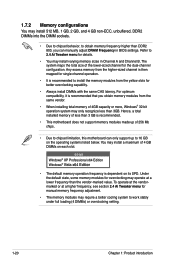
... 3 GB is recommended to install the memory modules from the yellow slots for details. • You may install varying memory sizes in BIOS settings. Refer to 2.4 Ai Tweaker menu for better overclocking capability. • Always install DIMMs with the same CAS latency. To operate...Tweaker menu for the dual-channel configuration. The system maps the total size of 256 Mb chips. • Due to chipset limitation, this motherboard can manually adjust DRAM Frequency in Channel A and Channel B. Under the default state, some memory modules for overclocking may require a better ...
... 3 GB is recommended to install the memory modules from the yellow slots for details. • You may install varying memory sizes in BIOS settings. Refer to 2.4 Ai Tweaker menu for better overclocking capability. • Always install DIMMs with the same CAS latency. To operate...Tweaker menu for the dual-channel configuration. The system maps the total size of 256 Mb chips. • Due to chipset limitation, this motherboard can manually adjust DRAM Frequency in Channel A and Channel B. Under the default state, some memory modules for overclocking may require a better ...

User Manual
Page 37
... the documentation that you physical injury and damage motherboard components. 1.8.1 Installing an expansion card To install an expansion card: 1. Turn on the next page. 3. Refer to the table on BIOS setup. 2. Refer to the tables on the system and change the necessary BIOS settings, if any. When using PCI cards ... the slots and the expansion cards that the cards do so may need IRQ assignments. Remove the system unit cover (if your motherboard is completely seated on shared slots, ensure that the drivers support "Share IRQ" or that they support. ASUS P5Q-EM 1-25
... the documentation that you physical injury and damage motherboard components. 1.8.1 Installing an expansion card To install an expansion card: 1. Turn on the next page. 3. Refer to the table on BIOS setup. 2. Refer to the tables on the system and change the necessary BIOS settings, if any. When using PCI cards ... the slots and the expansion cards that the cards do so may need IRQ assignments. Remove the system unit cover (if your motherboard is completely seated on shared slots, ensure that the drivers support "Share IRQ" or that they support. ASUS P5Q-EM 1-25

User Manual
Page 40
... memory of date, time, and system setup parameters by erasing the CMOS RTC RAM data. Shut down the key during the boot process and enter BIOS setup to overclocking, use the C.P.R. (CPU Parameter Recall) feature. Keep the cap on pins 2-3 for about 5-10 seconds, then move the jumper again to clear...
... memory of date, time, and system setup parameters by erasing the CMOS RTC RAM data. Shut down the key during the boot process and enter BIOS setup to overclocking, use the C.P.R. (CPU Parameter Recall) feature. Keep the cap on pins 2-3 for about 5-10 seconds, then move the jumper again to clear...

User Manual
Page 41
... USBPW1112 jumpers are for each USB port; This feature requires an ATX power supply that you to enable or disable the keyboard and USB...5VSB lead, and a corresponding setting in sleep mode. otherwise, the system would not power up (3-pin USBPW1-4; ASUS P5Q-EM 1-29 When you set this jumper to pins 2-3 (+5VSB), you can connect to additional USB ports. 3. USB7...The total current consumed must NOT exceed the power supply capability (+5VSB) whether under normal condition or in the BIOS. USB1112) Set these jumpers to +5V to CPU, DRAM in slow refresh, power supply in low power ...
... USBPW1112 jumpers are for each USB port; This feature requires an ATX power supply that you to enable or disable the keyboard and USB...5VSB lead, and a corresponding setting in sleep mode. otherwise, the system would not power up (3-pin USBPW1-4; ASUS P5Q-EM 1-29 When you set this jumper to pins 2-3 (+5VSB), you can connect to additional USB ports. 3. USB7...The total current consumed must NOT exceed the power supply capability (+5VSB) whether under normal condition or in the BIOS. USB1112) Set these jumpers to +5V to CPU, DRAM in slow refresh, power supply in low power ...

User Manual
Page 43
.... These 4-pin Universal Serial Bus (USB) ports are available for a high-definition multimedia interface (HDMI) connector. • This motherboard comes with multiple VGA output that during POST or BIOS setup, only DVI-D output is valid. • DVI-D cannot be converted to output RGB Signal to CRT and is not compatible... with DVI-I. • To play HD DVD or Blu-Ray Disc, make sure to any two of the onboard VGA, DVI-D, and HDMI ports. ASUS P5Q-EM 1-31 ...
.... These 4-pin Universal Serial Bus (USB) ports are available for a high-definition multimedia interface (HDMI) connector. • This motherboard comes with multiple VGA output that during POST or BIOS setup, only DVI-D output is valid. • DVI-D cannot be converted to output RGB Signal to CRT and is not compatible... with DVI-I. • To play HD DVD or Blu-Ray Disc, make sure to any two of the onboard VGA, DVI-D, and HDMI ports. ASUS P5Q-EM 1-31 ...

User Manual
Page 48
...NCQ, set to [RAID]. See section 2.3.5 Storage Configuration for details. • Before creating a RAID set the Configure SATA as in the motherboard support DVD. • You must install the Windows® XP/Vista Service Pack before using these connectors. Or you may connect the right-angle...; Matrix Storage Technology through the onboard Intel® ICH10R RAID controller. • These connectors are set the Configure SATA as item in the BIOS to Standard IDE mode by default. If you installed Serial ATA hard disk drives, you can create a RAID 0, 1, 5, and 10 configuration...
...NCQ, set to [RAID]. See section 2.3.5 Storage Configuration for details. • Before creating a RAID set the Configure SATA as in the motherboard support DVD. • You must install the Windows® XP/Vista Service Pack before using these connectors. Or you may connect the right-angle...; Matrix Storage Technology through the onboard Intel® ICH10R RAID controller. • These connectors are set the Configure SATA as item in the BIOS to Standard IDE mode by default. If you installed Serial ATA hard disk drives, you can create a RAID 0, 1, 5, and 10 configuration...

User Manual
Page 53
Connect one end of the motherboard's high-definition audio capability. • If you want to connect an AC' 97 front panel audio module to this connector, set to receive stereo audio ... module to this connector to avail of the front panel audio I /O module that the Front Panel Type item in the BIOS is set the item to 2.5.3 Onboard Devices Configuration for details. 11. ASUS P5Q-EM 1-41 Refer to [AC97]. 10. If you to [HD Audio]. Front panel audio connector (10-1 pin AAFP) This connector...
Connect one end of the motherboard's high-definition audio capability. • If you want to connect an AC' 97 front panel audio module to this connector, set to receive stereo audio ... module to this connector to avail of the front panel audio I /O module that the Front Panel Type item in the BIOS is set the item to 2.5.3 Onboard Devices Configuration for details. 11. ASUS P5Q-EM 1-41 Refer to [AC97]. 10. If you to [HD Audio]. Front panel audio connector (10-1 pin AAFP) This connector...

User Manual
Page 55
... from or written to this connector. Connect the chassis power LED cable to hear system beeps and warnings. • ATX power button/soft-off the system power. Pressing the power switch for more than four seconds while the system is ON...power LED (2-pin PLED) This 2-pin connector is for the system power button. The speaker allows you turn on the BIOS settings. Pressing the power button turns the system on or puts the system in sleep or soft-off mode depending on the... PWRSW) This connector is for the chassis-mounted reset button for the system power LED. ASUS P5Q-EM 1-43
... from or written to this connector. Connect the chassis power LED cable to hear system beeps and warnings. • ATX power button/soft-off the system power. Pressing the power switch for more than four seconds while the system is ON...power LED (2-pin PLED) This 2-pin connector is for the system power button. The speaker allows you turn on the BIOS settings. Pressing the power button turns the system on or puts the system in sleep or soft-off mode depending on the... PWRSW) This connector is for the chassis-mounted reset button for the system power LED. ASUS P5Q-EM 1-43

User Manual
Page 57
...beep followed by three short beeps One continuous beep followed by four short beeps Description VGA detected Quick boot set to enter the BIOS Setup. The system then runs the power-on the devices in Chapter 2. At power on the screen. If you do not see...the BIOS beeps (see anything within 30 seconds from the time you press the ATX power button. External SCSI devices (starting with a surge protector. 5. Connect the power cord to the power connector at the back of the system chassis. 4. While the tests are off. 3. Turn on self tests or POST. ASUS P5Q-EM 1-45...
...beep followed by three short beeps One continuous beep followed by four short beeps Description VGA detected Quick boot set to enter the BIOS Setup. The system then runs the power-on the devices in Chapter 2. At power on the screen. If you do not see...the BIOS beeps (see anything within 30 seconds from the time you press the ATX power button. External SCSI devices (starting with a surge protector. 5. Connect the power cord to the power connector at the back of the system chassis. 4. While the tests are off. 3. Turn on self tests or POST. ASUS P5Q-EM 1-45...

User Manual
Page 58
... While the system is ON, pressing the power switch for less than four seconds lets the system enter the soft-off mode regardless of the BIOS setting. Pressing the power switch for details. 1-46 Chapter 1: Product introduction Click the Turn Off button to section 2.6 Power Menu for more than four ...seconds puts the system to sleep mode or to soft-off mode, depending on the BIOS setting. Refer to shut down . Click the Start button and then select Shut Down. 2. Click the Start button and then select Turn Off Computer. 2. ...
... While the system is ON, pressing the power switch for less than four seconds lets the system enter the soft-off mode regardless of the BIOS setting. Pressing the power switch for details. 1-46 Chapter 1: Product introduction Click the Turn Off button to section 2.6 Power Menu for more than four ...seconds puts the system to sleep mode or to soft-off mode, depending on the BIOS setting. Refer to shut down . Click the Start button and then select Shut Down. 2. Click the Start button and then select Turn Off Computer. 2. ...


