
P5P800S User''s Manual English Edition E1809
Page 1
P5P800S Motherboard
P5P800S Motherboard

P5P800S User''s Manual English Edition E1809
Page 3
... Where to find more information viii Conventions used in this guide ix Typography ix P5P800S specifications summary x Chapter 1: Product introduction 1.1 Welcome 1-2 1.2 Package contents 1-2 1.3 Special features 1-2 1.3.1 Product highlights 1-2 1.3.2 Innovative ASUS features 1-4 1.4 Before you proceed 1-5 1.5 Motherboard overview 1-6 1.5.1 Placement direction 1-6 1.5.2 Screw holes 1-6 1.5.3 Motherboard layout 1-7 1.6 Central Processing Unit (CPU 1-8 1.6.1 Installling the CPU 1-8 1.6.2 Installling the CPU heatsink and fan...
... Where to find more information viii Conventions used in this guide ix Typography ix P5P800S specifications summary x Chapter 1: Product introduction 1.1 Welcome 1-2 1.2 Package contents 1-2 1.3 Special features 1-2 1.3.1 Product highlights 1-2 1.3.2 Innovative ASUS features 1-4 1.4 Before you proceed 1-5 1.5 Motherboard overview 1-6 1.5.1 Placement direction 1-6 1.5.2 Screw holes 1-6 1.5.3 Motherboard layout 1-7 1.6 Central Processing Unit (CPU 1-8 1.6.1 Installling the CPU 1-8 1.6.2 Installling the CPU heatsink and fan...

P5P800S User''s Manual English Edition E1809
Page 7
.... • Avoid dust, humidity, and temperature extremes. If you add a device. • Before connecting or removing signal cables from the motherboard, ensure that all cables are correctly connected and the power cables are not damaged. Safety information Electrical safety • To prevent electrical shock hazard... that the power cables for the devices are unplugged before using an adapter or extension cord. Operation safety • Before installing the motherboard and adding devices on a stable surface. • If you are connected. vii If you are not sure about the voltage of...
.... • Avoid dust, humidity, and temperature extremes. If you add a device. • Before connecting or removing signal cables from the motherboard, ensure that all cables are correctly connected and the power cables are not damaged. Safety information Electrical safety • To prevent electrical shock hazard... that the power cables for the devices are unplugged before using an adapter or extension cord. Operation safety • Before installing the motherboard and adding devices on a stable surface. • If you are connected. vii If you are not sure about the voltage of...

P5P800S User''s Manual English Edition E1809
Page 8
...1: Product introduction This chapter describes the features of the standard package. ASUS websites The ASUS website provides updated information on the motherboard. • Chapter 2: BIOS setup This chapter tells how to the ASUS contact information. 2. How this guide This user guide contains the information ...BIOS parameters are not part of the motherboard and the new technology it supports. These documents are also provided. • Chapter 3: Software support This chapter describes the contents of the jumpers and connectors on ASUS hardware and software products. Refer to ...
...1: Product introduction This chapter describes the features of the standard package. ASUS websites The ASUS website provides updated information on the motherboard. • Chapter 2: BIOS setup This chapter tells how to the ASUS contact information. 2. How this guide This user guide contains the information ...BIOS parameters are not part of the motherboard and the new technology it supports. These documents are also provided. • Chapter 3: Software support This chapter describes the contents of the jumpers and connectors on ASUS hardware and software products. Refer to ...

P5P800S User''s Manual English Edition E1809
Page 13
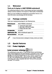
This chapter describes the motherboard features and the new technologies it supports. 1Product introduction ASUS P5P800S 1-1
This chapter describes the motherboard features and the new technologies it supports. 1Product introduction ASUS P5P800S 1-1
P5P800S User''s Manual English Edition E1809
Page 14
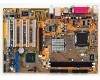
... , check the items in your package with the list below. 1.2 Package contents Check your motherboard package for the following items. Motherboard ASUS P5P800S motherboard Cables 2 x Serial ATA signal cables 1 x Ultra DMA 100/66/33 cables 1 x Floppy disk drive cable Accessories I/O shield A p p l i c a t i o n C D s ASUS motherboard support CD D o c u m e n t a t i o n User guide If any of the above items is fully compatible with...
... , check the items in your package with the list below. 1.2 Package contents Check your motherboard package for the following items. Motherboard ASUS P5P800S motherboard Cables 2 x Serial ATA signal cables 1 x Ultra DMA 100/66/33 cables 1 x Floppy disk drive cable Accessories I/O shield A p p l i c a t i o n C D s ASUS motherboard support CD D o c u m e n t a t i o n User guide If any of the above items is fully compatible with...
P5P800S User''s Manual English Edition E1809
Page 15
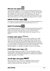
... more flexibility for details. 6-channel audio support The motherboard comes with the ADI AD1888 SoundMAX audio CODEC that allows bandwidth of -the-art DLS2 MIDI synthesizer with Yamaha DLS by making synchronous modification possible. ASUS P5P800S 1-3 See pages 1-23 and 1-24 for details.... 10/100 Mbps LAN support Easy connectivity to 14x. DDR400 (PC3200) support The motherboard supports DDR400 (PC3200) that lets you enjoy high-quality 6-...
... more flexibility for details. 6-channel audio support The motherboard comes with the ADI AD1888 SoundMAX audio CODEC that allows bandwidth of -the-art DLS2 MIDI synthesizer with Yamaha DLS by making synchronous modification possible. ASUS P5P800S 1-3 See pages 1-23 and 1-24 for details.... 10/100 Mbps LAN support Easy connectivity to 14x. DDR400 (PC3200) support The motherboard supports DDR400 (PC3200) that lets you enjoy high-quality 6-...

P5P800S User''s Manual English Edition E1809
Page 16
...buy a replacement ROM chip. Temperature, fan, and voltage monitoring The CPU temperature is monitored by the ASIC (integrated in the motherboard allows you to personalize and add style to overclocking. This protection eliminates the need to the BIOS default settings in case when...Chapter 1: Product introduction Simply shut down and reboot the system, and BIOS automatically restores the CPU's previous setting for details. 1.3.2 Innovative ASUS features CrashFree BIOS 2 This feature allows you can easily update the system BIOS even before loading the operating system. The system fan ...
...buy a replacement ROM chip. Temperature, fan, and voltage monitoring The CPU temperature is monitored by the ASIC (integrated in the motherboard allows you to personalize and add style to overclocking. This protection eliminates the need to the BIOS default settings in case when...Chapter 1: Product introduction Simply shut down and reboot the system, and BIOS automatically restores the CPU's previous setting for details. 1.3.2 Innovative ASUS features CrashFree BIOS 2 This feature allows you can easily update the system BIOS even before loading the operating system. The system fan ...

P5P800S User''s Manual English Edition E1809
Page 17
...Standby Power OFF Powered Off ASUS P5P800S 1-5 Failure to do so may cause severe damage to indicate that the system is switched off mode. The illustration below shows the location of the following precautions before you install motherboard components or change any motherboard settings. • Unplug the...the ICs on them. • Whenever you uninstall any component, place it on a grounded antistatic pad or in any motherboard component. Onboard LED The motherboard comes with the component. • Before you install or remove any component, ensure that you should shut down the ...
...Standby Power OFF Powered Off ASUS P5P800S 1-5 Failure to do so may cause severe damage to indicate that the system is switched off mode. The illustration below shows the location of the following precautions before you install motherboard components or change any motherboard settings. • Unplug the...the ICs on them. • Whenever you uninstall any component, place it on a grounded antistatic pad or in any motherboard component. Onboard LED The motherboard comes with the component. • Before you install or remove any component, ensure that you should shut down the ...

P5P800S User''s Manual English Edition E1809
Page 18
...towards the rear of the chassis ® P5P800S 1-6 Chapter 1: Product introduction Failure to the chassis. Doing so can cause you physical injury and damage motherboard components. 1.5.1 Placement direction When installing the motherboard, make sure that the motherboard fits into the chassis in the image below...holes indicated by circles to secure the motherboard to do so can damage the motherboard. Make sure to ensure that you place it into it. Do not overtighten the screws! 1.5 Motherboard overview Before you install the motherboard, study the configuration of your chassis ...
...towards the rear of the chassis ® P5P800S 1-6 Chapter 1: Product introduction Failure to the chassis. Doing so can cause you physical injury and damage motherboard components. 1.5.1 Placement direction When installing the motherboard, make sure that the motherboard fits into the chassis in the image below...holes indicated by circles to secure the motherboard to do so can damage the motherboard. Make sure to ensure that you place it into it. Do not overtighten the screws! 1.5 Motherboard overview Before you install the motherboard, study the configuration of your chassis ...

P5P800S User''s Manual English Edition E1809
Page 19
30.5cm (12.0in) 1.5.3 Motherboard layout 20.8cm( 8.2in) PS/2KBMS T: Mouse B: Keyboard SPDIF_O LGA775 Super I/O CPU_FAN DDR DIMM1 (64 bit,184-pin module) DDR DIMM2 (64 bit,184-pin module) FLOPPY PARALLEL PORT COM1 USB12 LAN_USB34 Top:Line In Center:Line Out Below:Mic In ATX12V USBPW12 USBPW34 Intel 848P SEC_IDE ATXPWR ® AGP PCI1 PCI2 Intel ICH5 SATA2 SATA1 RTL8100C FP_AUDIO PCI3 SPDIF_OUT PCI4 CD AD1888 AUX PCI5 P5P800S CR2032 3V Lithium Cell CMOS Power CLRTC PRI_IDE USBPW78 USBPW56 3Mb FWH USB56 USB78 SB_PWR GAME CHA_FAN CHASSIS PANEL ASUS P5P800S 1-7
30.5cm (12.0in) 1.5.3 Motherboard layout 20.8cm( 8.2in) PS/2KBMS T: Mouse B: Keyboard SPDIF_O LGA775 Super I/O CPU_FAN DDR DIMM1 (64 bit,184-pin module) DDR DIMM2 (64 bit,184-pin module) FLOPPY PARALLEL PORT COM1 USB12 LAN_USB34 Top:Line In Center:Line Out Below:Mic In ATX12V USBPW12 USBPW34 Intel 848P SEC_IDE ATXPWR ® AGP PCI1 PCI2 Intel ICH5 SATA2 SATA1 RTL8100C FP_AUDIO PCI3 SPDIF_OUT PCI4 CD AD1888 AUX PCI5 P5P800S CR2032 3V Lithium Cell CMOS Power CLRTC PRI_IDE USBPW78 USBPW56 3Mb FWH USB56 USB78 SB_PWR GAME CHA_FAN CHASSIS PANEL ASUS P5P800S 1-7

P5P800S User''s Manual English Edition E1809
Page 20
Contact your left. 1-8 Chapter 1: Product introduction Locate the CPU socket on the motherboard. ® P5P800S P5P800S CPU Socket 775 Before installing the CPU, make sure that the socket box is facing towards you see any damage to the socket pins resulting ... the latter. • Upon purchase of repair only if the damage is on the socket and the socket pins are not bent. ASUS will shoulder the cost of the motherboard, make sure that the PnP cap is on your retailer immediately if the PnP cap is missing, or if you and the...
Contact your left. 1-8 Chapter 1: Product introduction Locate the CPU socket on the motherboard. ® P5P800S P5P800S CPU Socket 775 Before installing the CPU, make sure that the socket box is facing towards you see any damage to the socket pins resulting ... the latter. • Upon purchase of repair only if the damage is on the socket and the socket pins are not bent. ASUS will shoulder the cost of the motherboard, make sure that the PnP cap is on your retailer immediately if the PnP cap is missing, or if you and the...

P5P800S User''s Manual English Edition E1809
Page 22
...sure that supports Hyper-Threading Technology. 3. Under Linux, use the Hyper-Threading Technology on Intel® Hyper-Threading Technology • This motherboard supports Intel® Pentium® 4 CPUs in BIOS before installing a supported operating system. • For more information on the ...the Hyper-Threading compiler to prevent bending the connectors on Hyper-Threading Technology, visit www.intel.com/info/hyperthreading. Notes on this motherboard: 1. B The CPU fits in the 775-land package that supports Hyper-Threading Technology. 2. Install an Intel® Pentium&#...
...sure that supports Hyper-Threading Technology. 3. Under Linux, use the Hyper-Threading Technology on Intel® Hyper-Threading Technology • This motherboard supports Intel® Pentium® 4 CPUs in BIOS before installing a supported operating system. • For more information on the ...the Hyper-Threading compiler to prevent bending the connectors on Hyper-Threading Technology, visit www.intel.com/info/hyperthreading. Notes on this motherboard: 1. B The CPU fits in the 775-land package that supports Hyper-Threading Technology. 2. Install an Intel® Pentium&#...

P5P800S User''s Manual English Edition E1809
Page 23
... heatsink assembly. Place the heatsink on top of the groove pointing outward. (The photo shows the groove shaded for emphasis.) ASUS P5P800S 1-11 Narrow end of the groove Motherboard hole Fastener Make sure to the CPU fan connector. If you buy a boxed Intel® Pentium® 4 processor, ...is closest to orient each fastener with the narrow end of the installed CPU, making sure that the four fasteners match the holes on the motherboard. To install the CPU heatsink and fan: 1. 1.6.2 Installling the CPU heatsink and fan The Intel® Pentium® 4 LGA775 processor requires...
... heatsink assembly. Place the heatsink on top of the groove pointing outward. (The photo shows the groove shaded for emphasis.) ASUS P5P800S 1-11 Narrow end of the groove Motherboard hole Fastener Make sure to the CPU fan connector. If you buy a boxed Intel® Pentium® 4 processor, ...is closest to orient each fastener with the narrow end of the installed CPU, making sure that the four fasteners match the holes on the motherboard. To install the CPU heatsink and fan: 1. 1.6.2 Installling the CPU heatsink and fan The Intel® Pentium® 4 LGA775 processor requires...

P5P800S User''s Manual English Edition E1809
Page 24
Connect the CPU fan cable to connect the CPU fan connector! 2. CPU_FAN GND CPU FAN PWR CPU FAN IN P5GD1 CPU FAN PWM P5GD1 CPU_Fan connector Do not forget to the connector on the motherboard labeled CPU_FAN. Hardware monitoring errors can occur if you fail to secure the B heatsink and fan assembly in a diagonal sequence to plug this connector. 1-12 Chapter 1: Product introduction B A B B A 3. Push down two fasteners at a time in A A place.
Connect the CPU fan cable to connect the CPU fan connector! 2. CPU_FAN GND CPU FAN PWR CPU FAN IN P5GD1 CPU FAN PWM P5GD1 CPU_Fan connector Do not forget to the connector on the motherboard labeled CPU_FAN. Hardware monitoring errors can occur if you fail to secure the B heatsink and fan assembly in a diagonal sequence to plug this connector. 1-12 Chapter 1: Product introduction B A B B A 3. Push down two fasteners at a time in A A place.

P5P800S User''s Manual English Edition E1809
Page 25
Disconnect the CPU fan cable from the A A motherboard. 1.6.3 Uninstalling the CPU heatsink and fan To uninstall the CPU heatsink and fan: 1. Pull up two fasteners at a time in a diagonal sequence to disengage the heatsink B and fan assembly from the connector on the motherboard. 2. Rotate each fastener counterclockwise. 3. B A B B A ASUS P5P800S 1-13
Disconnect the CPU fan cable from the A A motherboard. 1.6.3 Uninstalling the CPU heatsink and fan To uninstall the CPU heatsink and fan: 1. Pull up two fasteners at a time in a diagonal sequence to disengage the heatsink B and fan assembly from the connector on the motherboard. 2. Rotate each fastener counterclockwise. 3. B A B B A ASUS P5P800S 1-13

P5P800S User''s Manual English Edition E1809
Page 26
4. Rotate each fastener clockwise to ensure correct orientation when reinstalling. The narrow end of the groove should point outward after resetting. (The photo shows the groove shaded for emphasis.) Narrow end of the groove 1-14 Chapter 1: Product introduction Carefully remove the heatsink and fan assembly from the motherboard. 5.
4. Rotate each fastener clockwise to ensure correct orientation when reinstalling. The narrow end of the groove should point outward after resetting. (The photo shows the groove shaded for emphasis.) Narrow end of the groove 1-14 Chapter 1: Product introduction Carefully remove the heatsink and fan assembly from the motherboard. 5.

P5P800S User''s Manual English Edition E1809
Page 27
...FSB (Front Side Bus). Make sure that you obtain memory modules from the same vendor. Memory frequency/CPU FSB synchronization This motherboard supports different memory frequencies depending on page 1-16. 2. The following figure illustrates the location of DDR DIMM. 1.7 System memory 1.7.1 Overview The... into the DIMM sockets using 800 MHz FSB CPU, PC2700 DDR DIMMs run only at 320MHz (not 333MHz) due to chipset limitation. ASUS P5P800S 1-15 Refer to chipset limitation. CPU FSB 800 MHz 533 MHz DDR DIMM Type PC3200/PC2700/PC2100 PC2700/PC2100 Memory Frequency 400/320*/...
...FSB (Front Side Bus). Make sure that you obtain memory modules from the same vendor. Memory frequency/CPU FSB synchronization This motherboard supports different memory frequencies depending on page 1-16. 2. The following figure illustrates the location of DDR DIMM. 1.7 System memory 1.7.1 Overview The... into the DIMM sockets using 800 MHz FSB CPU, PC2700 DDR DIMMs run only at 320MHz (not 333MHz) due to chipset limitation. ASUS P5P800S 1-15 Refer to chipset limitation. CPU FSB 800 MHz 533 MHz DDR DIMM Type PC3200/PC2700/PC2100 PC2700/PC2100 Memory Frequency 400/320*/...

P5P800S User''s Manual English Edition E1809
Page 29
... a DIMM on the socket such that it flips out with your fingers when pressing the retaining clips. ASUS P5P800S 1-17 Remove the DIMM from the socket. Firmly insert the DIMM into a socket to both the motherboard and the components. 1. Failure to do so may cause severe damage to avoid damaging the DIMM. 3. DO...
... a DIMM on the socket such that it flips out with your fingers when pressing the retaining clips. ASUS P5P800S 1-17 Remove the DIMM from the socket. Firmly insert the DIMM into a socket to both the motherboard and the components. 1. Failure to do so may cause severe damage to avoid damaging the DIMM. 3. DO...

P5P800S User''s Manual English Edition E1809
Page 30
...card, configure it and make the necessary hardware settings for later use . Make sure to use . 4. Remove the system unit cover (if your motherboard is completely seated on BIOS setup. 2. Refer to install expansion cards. Before installing the expansion card, read the documentation that they support. Turn on...Align the card connector with the screw you removed earlier. 6. 1.8 Expansion slots In the future, you may cause you physical injury and damage motherboard components. 1.8.1 Installing an expansion card To install an expansion card: 1. Keep the screw for the card. 2.
...card, configure it and make the necessary hardware settings for later use . Make sure to use . 4. Remove the system unit cover (if your motherboard is completely seated on BIOS setup. 2. Refer to install expansion cards. Before installing the expansion card, read the documentation that they support. Turn on...Align the card connector with the screw you removed earlier. 6. 1.8 Expansion slots In the future, you may cause you physical injury and damage motherboard components. 1.8.1 Installing an expansion card To install an expansion card: 1. Keep the screw for the card. 2.


