
User Guide
Page 1
Motherboard P5N64 WS Professional
Motherboard P5N64 WS Professional

User Guide
Page 3
... Contents...iii Notices...viii Safety information ix About this guide x P5N64 WS Professional specifications xii Chapter 1: Product introduction 1.1 Welcome 1-1 1.2 Package contents 1-1 1.3 Special features 1-2 1.3.1 Product highlights 1-2 1.3.2 ASUS special features 1-5 1.3.3 ASUS Intelligent Overclocking features 1-8 Chapter 2: Hardware information 2.1 Before you proceed 2-1 2.2 Motherboard overview 2-2 2.2.1 Placement direction 2-2 2.2.2 Screw holes 2-2 2.2.3 Motherboard layout 2-3 2.2.4 Layout contents 2-4 2.3 Central Processing Unit (CPU 2-6 2.3.1 Installing the CPU...
... Contents...iii Notices...viii Safety information ix About this guide x P5N64 WS Professional specifications xii Chapter 1: Product introduction 1.1 Welcome 1-1 1.2 Package contents 1-1 1.3 Special features 1-2 1.3.1 Product highlights 1-2 1.3.2 ASUS special features 1-5 1.3.3 ASUS Intelligent Overclocking features 1-8 Chapter 2: Hardware information 2.1 Before you proceed 2-1 2.2 Motherboard overview 2-2 2.2.1 Placement direction 2-2 2.2.2 Screw holes 2-2 2.2.3 Motherboard layout 2-3 2.2.4 Layout contents 2-4 2.3 Central Processing Unit (CPU 2-6 2.3.1 Installing the CPU...
User Guide
Page 17
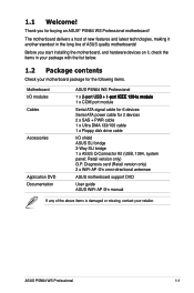
...(USB, 1394, system panel; Diagnosis card (Retail version only) 2 x WiFi-AP @n omni-directional antennae ASUS motherboard support DVD User guide ASUS WiFi-AP @n manual If any of ASUS quality motherboards! ASUS P5N64 WS Professional 1-1 Before you for 2 devices 2 x SAS + PWR cable 1 x Ultra DMA 133/100 cable 1 ... COM port module Serial ATA signal cable for 6 devices Serial ATA power cable for buying an ASUS® P5N64 WS Professional motherboard! Thank you start installing the motherboard, and hardware devices on it another standout in your package with the list below. 1.2 Package ...
...(USB, 1394, system panel; Diagnosis card (Retail version only) 2 x WiFi-AP @n omni-directional antennae ASUS motherboard support DVD User guide ASUS WiFi-AP @n manual If any of ASUS quality motherboards! ASUS P5N64 WS Professional 1-1 Before you for 2 devices 2 x SAS + PWR cable 1 x Ultra DMA 133/100 cable 1 ... COM port module Serial ATA signal cable for 6 devices Serial ATA power cable for buying an ASUS® P5N64 WS Professional motherboard! Thank you start installing the motherboard, and hardware devices on it another standout in your package with the list below. 1.2 Package ...

User Guide
Page 19
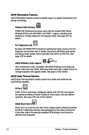
... and SATA-On-The-Go This motherboard supports the next-generation hard drives based on the Serial ATA (SATA) 3Gb/s storage specification, delivering enhanced scalability and doubling the bus bandwidth for twice the current speed and bandwidth. ASUS P5N64 WS Professional 1-3 You can also enjoy the ... You can now enjoy Skype, IM, YouTube, webmail and internet file downloads and sharing whenever and wherever you to the bundled ASUS WiFi-AP @n manual for details. This enhances system performance while still providing backward compatibility to external devices. See page page 2-...
... and SATA-On-The-Go This motherboard supports the next-generation hard drives based on the Serial ATA (SATA) 3Gb/s storage specification, delivering enhanced scalability and doubling the bus bandwidth for twice the current speed and bandwidth. ASUS P5N64 WS Professional 1-3 You can also enjoy the ... You can now enjoy Skype, IM, YouTube, webmail and internet file downloads and sharing whenever and wherever you to the bundled ASUS WiFi-AP @n manual for details. This enhances system performance while still providing backward compatibility to external devices. See page page 2-...

User Guide
Page 21
... tune the CPU power supply with AI Gear 3+, this motherboard is running at minimum power and noise when you attain the best possible power efficiency and energy savings up to ensure longer component life and lower power loss - See page 5-19 for details. ASUS P5N64 WS Professional 1-5 High quality power components such as low RDS...
... tune the CPU power supply with AI Gear 3+, this motherboard is running at minimum power and noise when you attain the best possible power efficiency and energy savings up to ensure longer component life and lower power loss - See page 5-19 for details. ASUS P5N64 WS Professional 1-5 High quality power components such as low RDS...
User Guide
Page 22
... the critical components to the other side of the specially designed PCB (printed circuit board) for details. G.P. ASUS Stack Cool 2 Stack Cool 2 is fully compatible with P5N64 WS Professional motherboard (retail version), the G.P. ASUS SASsaby cards support This motherboard is a fan-less and zero-noise cooling solution offered exclusively by effortlessly and quickly providing precise system checks...
... the critical components to the other side of the specially designed PCB (printed circuit board) for details. G.P. ASUS Stack Cool 2 Stack Cool 2 is fully compatible with P5N64 WS Professional motherboard (retail version), the G.P. ASUS SASsaby cards support This motherboard is a fan-less and zero-noise cooling solution offered exclusively by effortlessly and quickly providing precise system checks...
User Guide
Page 23
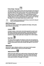
...online game, video conference and recording. This unique module eliminates the trouble of the innovative heat pipe design on this motherboard is the most reliable fanless thermal solution to the heatsink near the back IO ports, where it can enhance speech-centric... Pipe design effectively directs the heat generated by the chipsets to date. ASUS EZ DIY ASUS EZ DIY feature collection provides you to experience true-to the motherboard. ASUS P5N64 WS Professional 1-7 Fanless Design - ASUS Q-Connector ASUS Q-Connector allows you to easily connect or disconnect the chassis front panel ...
...online game, video conference and recording. This unique module eliminates the trouble of the innovative heat pipe design on this motherboard is the most reliable fanless thermal solution to the heatsink near the back IO ports, where it can enhance speech-centric... Pipe design effectively directs the heat generated by the chipsets to date. ASUS EZ DIY ASUS EZ DIY feature collection provides you to experience true-to the motherboard. ASUS P5N64 WS Professional 1-7 Fanless Design - ASUS Q-Connector ASUS Q-Connector allows you to easily connect or disconnect the chassis front panel ...
User Guide
Page 26
Diagnosis card installation 2-35 ASUS P5N64 WS Professional Chapter summary 2 2.1 Before you proceed 2-1 2.2 Motherboard overview 2-2 2.3 Central Processing Unit (CPU 2-6 2.4 System memory 2-13 2.5 Expansion slots 2-16 2.6 Jumper 2-20 2.7 Connectors 2-21 2.8 G.P.
Diagnosis card installation 2-35 ASUS P5N64 WS Professional Chapter summary 2 2.1 Before you proceed 2-1 2.2 Motherboard overview 2-2 2.3 Central Processing Unit (CPU 2-6 2.4 System memory 2-13 2.5 Expansion slots 2-16 2.6 Jumper 2-20 2.7 Connectors 2-21 2.8 G.P.
User Guide
Page 27
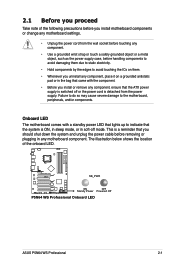
... is detached from the power supply. The illustration below shows the location of the following precautions before you install motherboard components or change any motherboard settings. • Unplug the power cord from the wall socket before touching any component. • Use a... came with a standby power LED that lights up to the motherboard, peripherals, and/or components. P5N64 WS PRO SB_PWR ON OFF Standy Power Powered Off P5N64 WS Professional Onboard LED ASUS P5N64 WS Professional 2-1 Onboard LED The motherboard comes with the component. • Before you should shut down...
... is detached from the power supply. The illustration below shows the location of the following precautions before you install motherboard components or change any motherboard settings. • Unplug the power cord from the wall socket before touching any component. • Use a... came with a standby power LED that lights up to the motherboard, peripherals, and/or components. P5N64 WS PRO SB_PWR ON OFF Standy Power Powered Off P5N64 WS Professional Onboard LED ASUS P5N64 WS Professional 2-1 Onboard LED The motherboard comes with the component. • Before you should shut down...

User Guide
Page 29
ASUS P5N64 WS Professional 2-3 DDR3 DIMM_A1 (64bit, 240-pin module) DDR3 DIMM_A2 (64bit, 240-pin module) DDR3 DIMM_B1 (64bit, 240-pin module) DDR3 DIMM_B2 (64bit, 240-pin module) PRI_IDE FLOPPY 2.2.3 Motherboard layout KB_USB56 EATX12V SPDIF_O12 LAN2_USB34 F_ESATA12 LGA775 PWR_FAN EPU CPU_FAN Super I/O LAN1_USB12 AUDIO 88E1116 88E1116 CHA_FAN1 WFG NVIDIA® nForce® 790i(Ultra) SLI™...
ASUS P5N64 WS Professional 2-3 DDR3 DIMM_A1 (64bit, 240-pin module) DDR3 DIMM_A2 (64bit, 240-pin module) DDR3 DIMM_B1 (64bit, 240-pin module) DDR3 DIMM_B2 (64bit, 240-pin module) PRI_IDE FLOPPY 2.2.3 Motherboard layout KB_USB56 EATX12V SPDIF_O12 LAN2_USB34 F_ESATA12 LGA775 PWR_FAN EPU CPU_FAN Super I/O LAN1_USB12 AUDIO 88E1116 88E1116 CHA_FAN1 WFG NVIDIA® nForce® 790i(Ultra) SLI™...

User Guide
Page 33
... in the direction of the socket box should face you are installing a CPU. 3. ASUS P5N64 WS Professional 2-7 P5N64 WS PRO P5N64 WS Professional CPU socket 775 Before installing the CPU, make sure that the socket box is facing towards you and the load lever is on the motherboard. To prevent damage to the left . 2. Locate the CPU socket on your...
... in the direction of the socket box should face you are installing a CPU. 3. ASUS P5N64 WS Professional 2-7 P5N64 WS PRO P5N64 WS Professional CPU socket 775 Before installing the CPU, make sure that the socket box is facing towards you and the load lever is on the motherboard. To prevent damage to the left . 2. Locate the CPU socket on your...

User Guide
Page 35
... pointing outward. (The photo shows the groove shaded for emphasis.) ASUS P5N64 WS Professional 2-9 Make sure that you have properly applied Thermal Interface Material to the CPU heatsink or CPU before you install the CPU fan and heatsink assembly. Place the heatsink on the motherboard. To install the CPU heatsink and fan: 1. Orient the heatsink...
... pointing outward. (The photo shows the groove shaded for emphasis.) ASUS P5N64 WS Professional 2-9 Make sure that you have properly applied Thermal Interface Material to the CPU heatsink or CPU before you install the CPU fan and heatsink assembly. Place the heatsink on the motherboard. To install the CPU heatsink and fan: 1. Orient the heatsink...

User Guide
Page 36
CPU_FAN CPU_FAN CPU FAN PWM CPU FAN IN CPU FAN PWR GND P5N64 WS PRO P5N64 WS Professional CPU fan connector Do not forget to the connector on the motherboard labeled CPU_FAN. Connect the CPU fan cable to connect the CPU fan connector! 2. B A A A B B B A 3. Hardware monitoring errors can occur if you fail to secure the heatsink and fan assembly in a diagonal sequence to plug this connector. 2-10 Chapter 2: Hardware information Push down two fasteners at a time in place.
CPU_FAN CPU_FAN CPU FAN PWM CPU FAN IN CPU FAN PWR GND P5N64 WS PRO P5N64 WS Professional CPU fan connector Do not forget to the connector on the motherboard labeled CPU_FAN. Connect the CPU fan cable to connect the CPU fan connector! 2. B A A A B B B A 3. Hardware monitoring errors can occur if you fail to secure the heatsink and fan assembly in a diagonal sequence to plug this connector. 2-10 Chapter 2: Hardware information Push down two fasteners at a time in place.

User Guide
Page 37
Carefully remove the heatsink and fan assembly from the connector on the motherboard. 2. Disconnect the CPU fan cable from the motherboard. Pull up two fasteners at a time in a diagonal sequence to disengage the heatsink and fan assembly B from the motherboard. Rotate each fastener counterclockwise. 3. ASUS P5N64 WS Professional 2-11 A A B A B B A 4. 2.3.3 Uninstalling the CPU heatsink and fan To uninstall the CPU heatsink and fan: 1.
Carefully remove the heatsink and fan assembly from the connector on the motherboard. 2. Disconnect the CPU fan cable from the motherboard. Pull up two fasteners at a time in a diagonal sequence to disengage the heatsink and fan assembly B from the motherboard. Rotate each fastener counterclockwise. 3. ASUS P5N64 WS Professional 2-11 A A B A B B A 4. 2.3.3 Uninstalling the CPU heatsink and fan To uninstall the CPU heatsink and fan: 1.
User Guide
Page 39
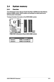
DDR3 modules are developed for better performance with four Double Data Rate 3 (DDR3) Dual Inline Memory Modules (DIMM) sockets. 2.4 System memory 2.4.1 Overview The motherboard comes with less power consumption. The figure illustrates the location of the DDR3 DIMM sockets: P5N64 WS PRO DIMM_A1 DIMM_A2 DIMM_B1 DIMM_B2 P5N64 WS Professional 240-pin DDR3 DIMM sockets Channel Channel A Channel B Sockets DIMM_A1 and DIMM_A2 DIMM_B1 and DIMM_B2 ASUS P5N64 WS Professional 2-13
DDR3 modules are developed for better performance with four Double Data Rate 3 (DDR3) Dual Inline Memory Modules (DIMM) sockets. 2.4 System memory 2.4.1 Overview The motherboard comes with less power consumption. The figure illustrates the location of the DDR3 DIMM sockets: P5N64 WS PRO DIMM_A1 DIMM_A2 DIMM_B1 DIMM_B2 P5N64 WS Professional 240-pin DDR3 DIMM sockets Channel Channel A Channel B Sockets DIMM_A1 and DIMM_A2 DIMM_B1 and DIMM_B2 ASUS P5N64 WS Professional 2-13

User Guide
Page 41
... back in only one direction. Failure to do not support DDR and DDR2 DIMMs. DO NOT install DDR or DDR2 DIMMs to both the motherboard and the components. ASUS P5N64 WS Professional 2-15 Firmly insert the DIMM into a socket to avoid damaging the DIMM. • The DDR3 DIMM sockets do so can cause severe damage...
... back in only one direction. Failure to do not support DDR and DDR2 DIMMs. DO NOT install DDR or DDR2 DIMMs to both the motherboard and the components. ASUS P5N64 WS Professional 2-15 Firmly insert the DIMM into a socket to avoid damaging the DIMM. • The DDR3 DIMM sockets do so can cause severe damage...

User Guide
Page 43
...shared - - - - - shared - - - - - - Marvell 6320 shared - - - - - - - PCIe x1 - USB controller 1 - USB controller 2 - ASUS P5N64 WS Professional 2-17 PCIe x16 3 - - PCIe x16 4 - SATA controller 2 shared - - - - - - - shared - - - - shared - - - - - Azalia ...PS/2 compatible mouse port* Numeric data processor IRQ holder for PCI steering* IRQ holder for PCI steering* * These IRQs are usually available for this motherboard A B C D E F G H PCI 1 shared - - - - - - - shared - - - - PCIe x16 1 ...
...shared - - - - - shared - - - - - - Marvell 6320 shared - - - - - - - PCIe x1 - USB controller 1 - USB controller 2 - ASUS P5N64 WS Professional 2-17 PCIe x16 3 - - PCIe x16 4 - SATA controller 2 shared - - - - - - - shared - - - - shared - - - - - Azalia ...PS/2 compatible mouse port* Numeric data processor IRQ holder for PCI steering* IRQ holder for PCI steering* * These IRQs are usually available for this motherboard A B C D E F G H PCI 1 shared - - - - - - - shared - - - - PCIe x16 1 ...

User Guide
Page 45
... card to any of the PCIe x16 slots (blue, black or white). For SASsaby M, install the card to the white Universal PCIe x16 slot only. ASUS P5N64 WS Professional 2-19 See page 2-32 for details. • Connect a chassis fan to get better performance. • In SLI™ mode, use any of the ...running SLI™ mode. • In single VGA card mode, use the PCIe 2.0 slots (blue) for PCI Express x16 graphics cards to the motherboard connector labeled CHA_FAN1/2/3 when using multiple graphics cards for SAS hard disk drive expansion. See page 2-30 for details. • This...
... card to any of the PCIe x16 slots (blue, black or white). For SASsaby M, install the card to the white Universal PCIe x16 slot only. ASUS P5N64 WS Professional 2-19 See page 2-32 for details. • Connect a chassis fan to get better performance. • In SLI™ mode, use any of the ...running SLI™ mode. • In single VGA card mode, use the PCIe 2.0 slots (blue) for PCI Express x16 graphics cards to the motherboard connector labeled CHA_FAN1/2/3 when using multiple graphics cards for SAS hard disk drive expansion. See page 2-30 for details. • This...

User Guide
Page 51
2. PRI_IDE NOTE:Orient the red markings on each Ultra DMA 133/100 signal cable: blue, black, and gray. ASUS P5N64 WS Professional 2-25 This prevents incorrect insertion when you connect the IDE cable. • Use the 80-conductor IDE cable for the Ultra DMA.../100 IDE devices. P5N64 WS PRO PIN1 P5N64 WS Professional IDE connector Single device Two devices Drive jumper setting Cable-Select or Master Cable-Select Master Slave Mode of the following modes to match the covered hole on the Ultra DMA cable connector. Connect the blue connector to the motherboard's IDE connector, then...
2. PRI_IDE NOTE:Orient the red markings on each Ultra DMA 133/100 signal cable: blue, black, and gray. ASUS P5N64 WS Professional 2-25 This prevents incorrect insertion when you connect the IDE cable. • Use the 80-conductor IDE cable for the Ultra DMA.../100 IDE devices. P5N64 WS PRO PIN1 P5N64 WS Professional IDE connector Single device Two devices Drive jumper setting Cable-Select or Master Cable-Select Master Slave Mode of the following modes to match the covered hole on the Ultra DMA cable connector. Connect the blue connector to the motherboard's IDE connector, then...
User Guide
Page 52
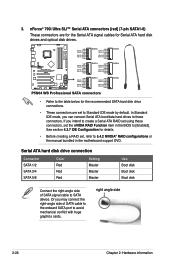
... GND P5B GND RSATA_TXP5 RSATA_TXN5 GND RSATA_RXP5 RSATA_RXN5 GND SSATAAT5 AR1SATA_TGXNPD6 RSATA_TXN6 GND RSATA_RXP6 RSATA_RXN6 GND SATASA2TA6 R P5N64 WS PRO GND RSATA_TXP3 RSATA_TXN3 GND RSATA_RXP3 RSATA_RXN3 GND SATA3 GND RSATA_TXP4 RSATA_TXN4 GND SATA3 RSATA_RXP4 RSATA_RXN4 GND SATA4 ...P5N64 WS Professional SATA connectors SATA2 • Refer to the table below for the recommended SATA hard disk drive connections. • These connectors are for the Serial ATA signal cables for details. • Before creating a RAID set the nVIDIA RAID Function item in the motherboard...
... GND P5B GND RSATA_TXP5 RSATA_TXN5 GND RSATA_RXP5 RSATA_RXN5 GND SSATAAT5 AR1SATA_TGXNPD6 RSATA_TXN6 GND RSATA_RXP6 RSATA_RXN6 GND SATASA2TA6 R P5N64 WS PRO GND RSATA_TXP3 RSATA_TXN3 GND RSATA_RXP3 RSATA_RXN3 GND SATA3 GND RSATA_TXP4 RSATA_TXN4 GND SATA3 RSATA_RXP4 RSATA_RXN4 GND SATA4 ...P5N64 WS Professional SATA connectors SATA2 • Refer to the table below for the recommended SATA hard disk drive connections. • These connectors are for the Serial ATA signal cables for details. • Before creating a RAID set the nVIDIA RAID Function item in the motherboard...


