
User Guide
Page 20
... chipset area when water-cooling or passive-cooling is specifically created to dissipate heat in heavy or light loadings. See page 5-24 for details. ASUS has devoted special efforts to digitally monitor and tune the CPU power supply with noise and malfunction likelihood... you are temporarily away. Q-Fan 2 1-4 Chapter 1: Product Introduction ASUS Motherboard's fansless concept is utilized, ensuring effective heat dissipation for details. See page 2-36 for the entire system. ASUS EPU The ASUS EPU utilizes innovative technology to address the thermal issues across the motherboard,...
... chipset area when water-cooling or passive-cooling is specifically created to dissipate heat in heavy or light loadings. See page 5-24 for details. ASUS has devoted special efforts to digitally monitor and tune the CPU power supply with noise and malfunction likelihood... you are temporarily away. Q-Fan 2 1-4 Chapter 1: Product Introduction ASUS Motherboard's fansless concept is utilized, ensuring effective heat dissipation for details. See page 2-36 for the entire system. ASUS EPU The ASUS EPU utilizes innovative technology to address the thermal issues across the motherboard,...
User Guide
Page 25
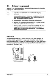
... removing or plugging in soft‑off or the power cord is ON, in sleep mode, or in any motherboard component. The green LED lights up to indicate that the system is detached from the wall socket before touching any component. • Use a grounded wrist strap...bag that came with a standby power LED. 2.1 Before you proceed Take note of the onboard LED. ® P5N-D P5N-D Onboard LED SB_PWR ON Standby Power OFF Powered Off ASUS P5N-D 2-1 The illustration below shows the location of the following precautions before you install motherboard components or change any motherboard...
... removing or plugging in soft‑off or the power cord is ON, in sleep mode, or in any motherboard component. The green LED lights up to indicate that the system is detached from the wall socket before touching any component. • Use a grounded wrist strap...bag that came with a standby power LED. 2.1 Before you proceed Take note of the onboard LED. ® P5N-D P5N-D Onboard LED SB_PWR ON Standby Power OFF Powered Off ASUS P5N-D 2-1 The illustration below shows the location of the following precautions before you install motherboard components or change any motherboard...

User Guide
Page 28
2.2.4 Slots 1. 2. 3. 4. Side Speaker Out port (gray) 11. Serial port 14. Line In port (light blue) 8. Optical S/PDIF Out port 15. LAN (RJ-45) port 5. PS/2 keyboard port (purple) Page 2-13 2-21 2-21 2-21 Page 2-23 2-24 2-24...25 2-25 2-25 2-25 2-26 2-26 2-26 2-26 2-26 2-26 2-26 2-26 2-4 Chapter 2: Hardware information Keyboard power (3-pin KBPWR) Rear panel connectors 1. PS/2 mouse port (green) 2. IEEE 1394a port 4. Center/Subwoofer port (orange) 6. Rear Speaker Out port (black) 7. USB 2.0 ports 3 and 4 13. Line Out port (lime) 9. Coaxial S/PDIF Out...
2.2.4 Slots 1. 2. 3. 4. Side Speaker Out port (gray) 11. Serial port 14. Line In port (light blue) 8. Optical S/PDIF Out port 15. LAN (RJ-45) port 5. PS/2 keyboard port (purple) Page 2-13 2-21 2-21 2-21 Page 2-23 2-24 2-24...25 2-25 2-25 2-25 2-26 2-26 2-26 2-26 2-26 2-26 2-26 2-26 2-4 Chapter 2: Hardware information Keyboard power (3-pin KBPWR) Rear panel connectors 1. PS/2 mouse port (green) 2. IEEE 1394a port 4. Center/Subwoofer port (orange) 6. Rear Speaker Out port (black) 7. USB 2.0 ports 3 and 4 13. Line Out port (lime) 9. Coaxial S/PDIF Out...

User Guide
Page 42
... supply before adding or removing DIMMs or other system components. The DIMM might get damaged when it fits in only one direction. Support the DIMM lightly with your fingers when pressing the retaining clips.
... supply before adding or removing DIMMs or other system components. The DIMM might get damaged when it fits in only one direction. Support the DIMM lightly with your fingers when pressing the retaining clips.

User Guide
Page 49
...(light blue). This port connects a headphone or a speaker. ASUS P5N-D 2-25 Parallel port. LAN port LED indications Activity Link LED Status Description OFF No link ORANGE Linked BLINKING Data activity Speed LED Status Description ACT/LINK SPEED LED LED OFF 10 Mbps connection ORANGE 100 Mbps connection GREEN...CD, DVD player, or other devices. 3. This port is for the LAN port LED indications. LAN (RJ-45) port. PS/2 mouse port (green). IEEE 1394a port. Refer to a Local Area Network (LAN) through a network hub. This port connects the rear speakers in a 4-channel, 6-...
...(light blue). This port connects a headphone or a speaker. ASUS P5N-D 2-25 Parallel port. LAN port LED indications Activity Link LED Status Description OFF No link ORANGE Linked BLINKING Data activity Speed LED Status Description ACT/LINK SPEED LED LED OFF 10 Mbps connection ORANGE 100 Mbps connection GREEN...CD, DVD player, or other devices. 3. This port is for the LAN port LED indications. LAN (RJ-45) port. PS/2 mouse port (green). IEEE 1394a port. Refer to a Local Area Network (LAN) through a network hub. This port connects the rear speakers in a 4-channel, 6-...

User Guide
Page 50
... a coaxial S/PDIF cable. 16. Refer to the audio configuration table below for connecting USB 2.0 devices. 12. Coaxial S/PDIF Out port. Audio 2, 4, 6, or 8-channel configuration Port Light Blue Lime Pink Orange Black Gray Headset 2-channel Line In Line Out Mic In - - - 4-channel Line In Front Speaker Out Mic In - USB 2.0 ports 3 and...
... a coaxial S/PDIF cable. 16. Refer to the audio configuration table below for connecting USB 2.0 devices. 12. Coaxial S/PDIF Out port. Audio 2, 4, 6, or 8-channel configuration Port Light Blue Lime Pink Orange Black Gray Headset 2-channel Line In Line Out Mic In - - - 4-channel Line In Front Speaker Out Mic In - USB 2.0 ports 3 and...

User Guide
Page 58
...for the chassis-mounted system warning speaker. System panel connector (20-8 pin PANEL) This connector supports several chassis-mounted functions. The IDE LED lights up when you to this connector. Pressing the power button turns the system on or puts the system in sleep mode. • Hard disk...(4-pin SPEAKER) This 4-pin connector is for the system power LED. PWR Ground Reset Ground 11. PLED+ PLED+5V Ground Ground Speaker ® P5N-D IDE_LED+ IDE_LED- Connect the HDD Activity LED cable to hear system beeps and warnings. • ATX power button/soft-off mode depending on the...
...for the chassis-mounted system warning speaker. System panel connector (20-8 pin PANEL) This connector supports several chassis-mounted functions. The IDE LED lights up when you to this connector. Pressing the power button turns the system on or puts the system in sleep mode. • Hard disk...(4-pin SPEAKER) This 4-pin connector is for the system power LED. PWR Ground Reset Ground 11. PLED+ PLED+5V Ground Ground Speaker ® P5N-D IDE_LED+ IDE_LED- Connect the HDD Activity LED cable to hear system beeps and warnings. • ATX power button/soft-off mode depending on the...

User Guide
Page 63
...the time you press the ATX power button. After applying power, the system power LED on the system front panel case lights up or switch between orange and green after the system LED turns on. Connect the power cord to a power outlet that all the connections, replace the ...5. Turn on self tests or POST. 3.1 Starting up when you turned on the power, the system may light up . Monitor b. The system then runs the power-on the devices in Chapter 4. ASUS�P�5�N��-D� 3-1 For systems with the last device on , hold down the key...
...the time you press the ATX power button. After applying power, the system power LED on the system front panel case lights up or switch between orange and green after the system LED turns on. Connect the power cord to a power outlet that all the connections, replace the ...5. Turn on self tests or POST. 3.1 Starting up when you turned on the power, the system may light up . Monitor b. The system then runs the power-on the devices in Chapter 4. ASUS�P�5�N��-D� 3-1 For systems with the last device on , hold down the key...


