

User Guide
Page 3
... this guide ix Typography x P5MT-S specifications summary xi Chapter 1: Product introduction 1.1 Welcome 1-1 1.2 Package contents 1-1 1.3 Special features 1-2 1.3.1 Product highlights 1-2 1.3.2 Innovative ASUS features 1-4 Chapter 2: Hardware information 2.1 Before you proceed 2-1 Onboard LEDs 2-1 2.2 Motherboard overview 2-2 2.2.1 Placement direction 2-2 2.2.2 Screw holes 2-2 2.2.3 Motherboard layout 2-3 2.2.4 Layout Contents 2-4 2.3 Central Processing Unit (CPU 2-6 2.3.1 Installing the CPU 2-6 2.3.2 Installing the CPU heatsink and fan 2-9 2.3.3 Uninstalling...
... this guide ix Typography x P5MT-S specifications summary xi Chapter 1: Product introduction 1.1 Welcome 1-1 1.2 Package contents 1-1 1.3 Special features 1-2 1.3.1 Product highlights 1-2 1.3.2 Innovative ASUS features 1-4 Chapter 2: Hardware information 2.1 Before you proceed 2-1 Onboard LEDs 2-1 2.2 Motherboard overview 2-2 2.2.1 Placement direction 2-2 2.2.2 Screw holes 2-2 2.2.3 Motherboard layout 2-3 2.2.4 Layout Contents 2-4 2.3 Central Processing Unit (CPU 2-6 2.3.1 Installing the CPU 2-6 2.3.2 Installing the CPU heatsink and fan 2-9 2.3.3 Uninstalling...

User Guide
Page 5
Contents 4.4.2 CPU Configuration 4-19 4.4.3 Chipset Configuration 4-21 4.4.4 Onboard Devices Configuration 4-25 4.4.5 PCI PnP 4-26 4.5 Power Configuration 4-27 4.5.1 APM Con&#...
Contents 4.4.2 CPU Configuration 4-19 4.4.3 Chipset Configuration 4-21 4.4.4 Onboard Devices Configuration 4-25 4.4.5 PCI PnP 4-26 4.5 Power Configuration 4-27 4.5.1 APM Con&#...
User Guide
Page 11
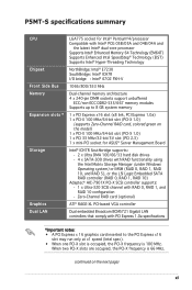
...controller Dual embedded Broadcom BCM5721 Gigabit LAN controllers that comply with RAID 0, RAID 1, and RAID 10 configuration - P5MT-S specifications summary CPU Chipset Front Side Bus Memory Expansion slots * Storage Graphics Dual LAN LGA775 socket for Intel® Pentium®4/processor Compatible ...the model) 1 x PCI-X 100 MHz/64-bit slot (PCI-X 1.0) 1 x PCI 33 MHz/32-bit/5V slot (PCI 2.3) 1 x mini-PCI socket for ASUS® Server Management Board Intel® ICH7R Southbridge supports: - 2 x Ultra DMA 100/66/33 hard disk drives - 4 x SATA-300 drives with RAID functionality ...
...controller Dual embedded Broadcom BCM5721 Gigabit LAN controllers that comply with RAID 0, RAID 1, and RAID 10 configuration - P5MT-S specifications summary CPU Chipset Front Side Bus Memory Expansion slots * Storage Graphics Dual LAN LGA775 socket for Intel® Pentium®4/processor Compatible ...the model) 1 x PCI-X 100 MHz/64-bit slot (PCI-X 1.0) 1 x PCI 33 MHz/32-bit/5V slot (PCI 2.3) 1 x mini-PCI socket for ASUS® Server Management Board Intel® ICH7R Southbridge supports: - 2 x Ultra DMA 100/66/33 hard disk drives - 4 x SATA-300 drives with RAID functionality ...

User Guide
Page 12
...P5MT-S specifications summary USB Special features BIOS features Rear panel Internal connectors Power Requirement Form Factor Support CD contents Intel ICH7R Southbridge supports: - 4 USB 2.0 ports (two on the rear panel, two on the front panel) ASUS Smart Fan I/II ASUS CrashFree BIOS 2 ASUS...IDE connector 4 x Serial ATA connectors 1 x Hard disk activity LED connector 1 x 68-pin SCSI connector 2 x Front fan connectors 2 x Rear fan connectors 2 x CPU fan connectors 1 x 24-pin ATX power connector 1 x 8-pin ATX 12 V power connector 1 x Power supply SMBUS connector 1 x Serial port (COM2) 1 x...
...P5MT-S specifications summary USB Special features BIOS features Rear panel Internal connectors Power Requirement Form Factor Support CD contents Intel ICH7R Southbridge supports: - 4 USB 2.0 ports (two on the rear panel, two on the front panel) ASUS Smart Fan I/II ASUS CrashFree BIOS 2 ASUS...IDE connector 4 x Serial ATA connectors 1 x Hard disk activity LED connector 1 x 68-pin SCSI connector 2 x Front fan connectors 2 x Rear fan connectors 2 x CPU fan connectors 1 x 24-pin ATX power connector 1 x 8-pin ATX 12 V power connector 1 x Power supply SMBUS connector 1 x Serial port (COM2) 1 x...

User Guide
Page 16
... that speeds up the PCI bus. Enhanced Intel SpeedStep® Technology (EIST) The Enhanced Intel SpeedStep® Technology (EIST) intelligently manages the CPU resources by carrying data in the 775-land package. See page 4-20 and the Appendix for details. PCI Express™ interface The motherboard fully... 4 processor in packets. PCI Express features point-to-point serial interconnections between devices and allows higher clockspeeds by automatically adjusting the CPU voltage and core frequency depending on 64-bit operating systems and access larger amounts of up to run on the...
... that speeds up the PCI bus. Enhanced Intel SpeedStep® Technology (EIST) The Enhanced Intel SpeedStep® Technology (EIST) intelligently manages the CPU resources by carrying data in the 775-land package. See page 4-20 and the Appendix for details. PCI Express™ interface The motherboard fully... 4 processor in packets. PCI Express features point-to-point serial interconnections between devices and allows higher clockspeeds by automatically adjusting the CPU voltage and core frequency depending on 64-bit operating systems and access larger amounts of up to run on the...
User Guide
Page 18
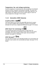
... system fan rotations per minute (RPM) is monitored by the ASIC (integrated in the Winbond hardware monitor) to ensure stable supply of ASUS Smart Fan technology. The ASIC monitors the voltage levels to prevent overheating and damage. See page 4-31 for details. See page 4-35...you to your system with customizable boot logos. Temperature, fan, and voltage monitoring The CPU temperature is monitored for timely failure detection. See page 4-30 for details. 1-4 Chapter 1: Product introduction ASUS MyLogo2™ This new feature present in case when the BIOS codes and data are...
... system fan rotations per minute (RPM) is monitored by the ASIC (integrated in the Winbond hardware monitor) to ensure stable supply of ASUS Smart Fan technology. The ASIC monitors the voltage levels to prevent overheating and damage. See page 4-31 for details. See page 4-35...you to your system with customizable boot logos. Temperature, fan, and voltage monitoring The CPU temperature is monitored for timely failure detection. See page 4-30 for details. 1-4 Chapter 1: Product introduction ASUS MyLogo2™ This new feature present in case when the BIOS codes and data are...

User Guide
Page 20
Chapter summary 2 2.1 Before you proceed 2-1 2.2 Motherboard overview 2-2 2.3 Central Processing Unit (CPU 2-6 2.4 System memory 2-13 2.5 Expansion slots 2-15 2.6 Jumpers 2-18 2.7 Connectors 2-23 ASUS P5MT-S
Chapter summary 2 2.1 Before you proceed 2-1 2.2 Motherboard overview 2-2 2.3 Central Processing Unit (CPU 2-6 2.4 System memory 2-13 2.5 Expansion slots 2-15 2.6 Jumpers 2-18 2.7 Connectors 2-23 ASUS P5MT-S

User Guide
Page 24
... 2-22 Page 2-23 2-23 2-23 2-23 2-23 2-23 2-23 2-23 2-4 Chapter 2: Hardware information SCSI controller setting (3-pin SCSI_EN1) 9. CPU fan pin selection (3-pin FM_CPU1, FM_CPU2) 3. Parallel port 3. VGA port 7. 2.2.4 Layout contents Slots/Sockets 1. CPU socket 2. DDR2 DIMM slots 3. PCI/PCI-X/PCI Express slots 4. Keyboard/Mouse power (3-pin KBPWR1) 5. Gigabit LAN controller setting...
... 2-22 Page 2-23 2-23 2-23 2-23 2-23 2-23 2-23 2-23 2-4 Chapter 2: Hardware information SCSI controller setting (3-pin SCSI_EN1) 9. CPU fan pin selection (3-pin FM_CPU1, FM_CPU2) 3. Parallel port 3. VGA port 7. 2.2.4 Layout contents Slots/Sockets 1. CPU socket 2. DDR2 DIMM slots 3. PCI/PCI-X/PCI Express slots 4. Keyboard/Mouse power (3-pin KBPWR1) 5. Gigabit LAN controller setting...
User Guide
Page 26
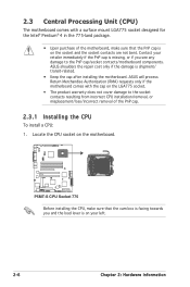
... on the motherboard. ® P5MT-S P5MT-S CPU Socket 775 Before installing the CPU, make sure that the cam box is on the socket and the socket contacts are not bent. ASUS will process Return Merchandise Authorization (RMA) requests only if the motherboard comes with a surface mount LGA775 ...cap is facing towards you see any damage to the socket contacts resulting from incorrect CPU installation/removal, or misplacement/loss/incorrect removal of the PnP cap. 2.3.1 Installing the CPU To install a CPU: 1. ASUS shoulders the repair cost only if the damage is on your left. 2-6 Chapter ...
... on the motherboard. ® P5MT-S P5MT-S CPU Socket 775 Before installing the CPU, make sure that the cam box is on the socket and the socket contacts are not bent. ASUS will process Return Merchandise Authorization (RMA) requests only if the motherboard comes with a surface mount LGA775 ...cap is facing towards you see any damage to the socket contacts resulting from incorrect CPU installation/removal, or misplacement/loss/incorrect removal of the PnP cap. 2.3.1 Installing the CPU To install a CPU: 1. ASUS shoulders the repair cost only if the damage is on your left. 2-6 Chapter ...
User Guide
Page 27
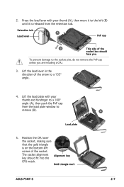
...the direction of the socket. Position the CPU over the socket, making sure that the gold triangle is released from the load plate window to the socket pins, do not remove the PnP cap unless you . Load plate 5. 2. Gold triangle mark ASUS P5MT-S A 2-7 Retention tab A Load ...lever PnP cap B This side of the socket box should fit into the Alignment key CPU notch. Lift the load plate with your thumb and forefinger to a 135...
...the direction of the socket. Position the CPU over the socket, making sure that the gold triangle is released from the load plate window to the socket pins, do not remove the PnP cap unless you . Load plate 5. 2. Gold triangle mark ASUS P5MT-S A 2-7 Retention tab A Load ...lever PnP cap B This side of the socket box should fit into the Alignment key CPU notch. Lift the load plate with your thumb and forefinger to a 135...

User Guide
Page 28
The CPU fits in only one correct orientation. Refer to prevent bending the connectors on these CPU features. 2-8 Chapter 2: Hardware information DO NOT force the CPU into the retention tab. Close the load plate (A), then A push the load lever (B) until it snaps into the socket to the Appendix for more information on the socket and damaging the CPU! 6. B The motherboard supports Intel® Pentium® 4 LGA775 processors with the Intel® Enhanced Memory 64 Technology (EM64T), Enhanced Intel SpeedStep® Technology (EIST), and Hyper-Threading Technology.
The CPU fits in only one correct orientation. Refer to prevent bending the connectors on these CPU features. 2-8 Chapter 2: Hardware information DO NOT force the CPU into the retention tab. Close the load plate (A), then A push the load lever (B) until it snaps into the socket to the Appendix for more information on the socket and damaging the CPU! 6. B The motherboard supports Intel® Pentium® 4 LGA775 processors with the Intel® Enhanced Memory 64 Technology (EM64T), Enhanced Intel SpeedStep® Technology (EIST), and Hyper-Threading Technology.

User Guide
Page 29
...the groove pointing outward. (The photo shows the groove shaded for emphasis.) ASUS P5MT-S 2-9 Orient the heatsink and fan assembly such that the four fasteners match the holes on the motherboard. To install the CPU heatsink and fan: 1. Narrow end of the groove Motherboard hole Fastener Make... to ensure optimum thermal condition and performance. • When you buy a boxed Intel® Pentium® 4 processor, the package includes the CPU fan and heatsink assembly. • Your Intel® Pentium® 4 LGA775 heatsink and fan assembly comes in a push-pin design and requires...
...the groove pointing outward. (The photo shows the groove shaded for emphasis.) ASUS P5MT-S 2-9 Orient the heatsink and fan assembly such that the four fasteners match the holes on the motherboard. To install the CPU heatsink and fan: 1. Narrow end of the groove Motherboard hole Fastener Make... to ensure optimum thermal condition and performance. • When you buy a boxed Intel® Pentium® 4 processor, the package includes the CPU fan and heatsink assembly. • Your Intel® Pentium® 4 LGA775 heatsink and fan assembly comes in a push-pin design and requires...

User Guide
Page 30
...P5MT-S GND FANPWR Rotation PWM CPU_FAN2 P5MT-S CPU Fan Connectors CPU_FAN2 PWM Rotation FANPWR GND • Do not forget to "2.6 Jumpers" for deatails. 2-10 Chapter 2: Hardware information Refer to connect the CPU fan connector! Connect the CPU fan cable to use a 3-pin or 4-pin fan cable plug. Set the CPU...motherboard labeled CPU_FAN1/CPU_FAN2. Hardware monitoring errors can occur if you fail to plug this connector. • If there is only one CPU fan cable, connect it to do so may cause hardware monitoring errors. Failure to the connector labeled CPU_FAN1. A A A B B...
...P5MT-S GND FANPWR Rotation PWM CPU_FAN2 P5MT-S CPU Fan Connectors CPU_FAN2 PWM Rotation FANPWR GND • Do not forget to "2.6 Jumpers" for deatails. 2-10 Chapter 2: Hardware information Refer to connect the CPU fan connector! Connect the CPU fan cable to use a 3-pin or 4-pin fan cable plug. Set the CPU...motherboard labeled CPU_FAN1/CPU_FAN2. Hardware monitoring errors can occur if you fail to plug this connector. • If there is only one CPU fan cable, connect it to do so may cause hardware monitoring errors. Failure to the connector labeled CPU_FAN1. A A A B B...
User Guide
Page 31
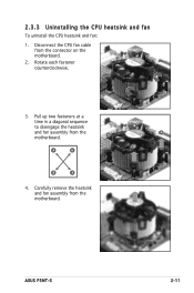
A A B A B B A 4. 2.3.3 Uninstalling the CPU heatsink and fan To uninstall the CPU heatsink and fan: 1. Pull up two fasteners at a time in a diagonal sequence to disengage the heatsink B and fan assembly from the motherboard. Carefully remove the heatsink and fan assembly from the motherboard. Disconnect the CPU fan cable from the connector on the motherboard. 2. ASUS P5MT-S 2-11 Rotate each fastener counterclockwise. 3.
A A B A B B A 4. 2.3.3 Uninstalling the CPU heatsink and fan To uninstall the CPU heatsink and fan: 1. Pull up two fasteners at a time in a diagonal sequence to disengage the heatsink B and fan assembly from the motherboard. Carefully remove the heatsink and fan assembly from the motherboard. Disconnect the CPU fan cable from the connector on the motherboard. 2. ASUS P5MT-S 2-11 Rotate each fastener counterclockwise. 3.

User Guide
Page 32
Rotate each fastener clockwise to the documentation in the boxed or stand-alone CPU fan package for emphasis.) Narrow end of the groove Refer to ensure correct orientation when reinstalling. 5. The narrow end of the groove should point outward after resetting. (The photo shows the groove shaded for detailed information on CPU fan installation. 2-12 Chapter 2: Hardware information
Rotate each fastener clockwise to the documentation in the boxed or stand-alone CPU fan package for emphasis.) Narrow end of the groove Refer to ensure correct orientation when reinstalling. 5. The narrow end of the groove should point outward after resetting. (The photo shows the groove shaded for detailed information on CPU fan installation. 2-12 Chapter 2: Hardware information

User Guide
Page 39
...). Set to +5VSB to CPU, DRAM in slow refresh, power supply in reduced power mode). ASUS P5MT-S 2-19 otherwise, the system would not power up the computer from S1 sleep mode (CPU stopped, DRAM refreshed, system running in sleep mode. USBPW12 12 23 ® P5MT-S +5V (Default) +5VSB... USBPW34 32 21 +5VSB P5MT-S USB Device Wake-Up +5V ...
...). Set to +5VSB to CPU, DRAM in slow refresh, power supply in reduced power mode). ASUS P5MT-S 2-19 otherwise, the system would not power up the computer from S1 sleep mode (CPU stopped, DRAM refreshed, system running in sleep mode. USBPW12 12 23 ® P5MT-S +5V (Default) +5VSB... USBPW34 32 21 +5VSB P5MT-S USB Device Wake-Up +5V ...

User Guide
Page 49
CPU and system fan connectors (3-pin CPU_FAN1/2, REAR_FAN1/2, FRNT_FAN1/2) The fan connectors ... Connect the fan cables to the fan connectors on the fan connectors! ® P5MT-S CPU_FAN1 CPU_FAN2 REAR_FAN1 REAR_FAN2 FRNT_FAN1 FRNT_FAN2 P5MT-S Fan Connectors GND FANPWR Rotation PWM CPU_FAN1 CPU_FAN2 PWM Rotation FANPWR GND REAR_FAN1 Rotation FANPWR...an SMBus host and/or other SMBus devices using the SMBus interface. ® P5MT-S FANOUT I2C_CLK GND I2C_DATA +5V 1 BPSMB1 P5MT-S SMBus Connector ASUS P5MT-S 2-29 Do not place jumper caps on the motherboard, making sure that the...
CPU and system fan connectors (3-pin CPU_FAN1/2, REAR_FAN1/2, FRNT_FAN1/2) The fan connectors ... Connect the fan cables to the fan connectors on the fan connectors! ® P5MT-S CPU_FAN1 CPU_FAN2 REAR_FAN1 REAR_FAN2 FRNT_FAN1 FRNT_FAN2 P5MT-S Fan Connectors GND FANPWR Rotation PWM CPU_FAN1 CPU_FAN2 PWM Rotation FANPWR GND REAR_FAN1 Rotation FANPWR...an SMBus host and/or other SMBus devices using the SMBus interface. ® P5MT-S FANOUT I2C_CLK GND I2C_DATA +5V 1 BPSMB1 P5MT-S SMBus Connector ASUS P5MT-S 2-29 Do not place jumper caps on the motherboard, making sure that the...

User Guide
Page 75
... the auto-detected BIOS information. The BIOS automatically detects the items in this menu. Processor Displays the auto-detected CPU specification. ASUS P5MT-S 4-17 System Memory Displays the auto-detected total system memory. Main BIOS SETUP UTILITY AMIBIOS Version : 08.00....11 Build Date : 12/01/05 Processor Type Speed Count : Genuine Intel(R) CPU 3.20GHz : 3200 MHz : 1 System Memory Total : 1024MB Select ...
... the auto-detected BIOS information. The BIOS automatically detects the items in this menu. Processor Displays the auto-detected CPU specification. ASUS P5MT-S 4-17 System Memory Displays the auto-detected total system memory. Main BIOS SETUP UTILITY AMIBIOS Version : 08.00....11 Build Date : 12/01/05 Processor Type Speed Count : Genuine Intel(R) CPU 3.20GHz : 3200 MHz : 1 System Memory Total : 1024MB Select ...

User Guide
Page 76
Select Screen Select Item +- Select Screen Select Item +- MPS Revision [1.4] Allows you to change the settings for the CPU and other system devices. Configuration options: [1.1] [1.4] 4-18 Chapter 4: BIOS setup Change Option F1 General Help F10 Save and Exit...;guration MPS Revision BIOS SETUP UTILITY [1.4] Select MPS Revision. Main Advanced Power BIOS SETUP UTILITY Server Boot Exit MPS Configuration CPU Configuration Chipset Onboard Devices Configuration PCIPnP Configure the MultiProcessor Table. 4.4 Advanced menu The Advanced menu items ...
Select Screen Select Item +- Select Screen Select Item +- MPS Revision [1.4] Allows you to change the settings for the CPU and other system devices. Configuration options: [1.1] [1.4] 4-18 Chapter 4: BIOS setup Change Option F1 General Help F10 Save and Exit...;guration MPS Revision BIOS SETUP UTILITY [1.4] Select MPS Revision. Main Advanced Power BIOS SETUP UTILITY Server Boot Exit MPS Configuration CPU Configuration Chipset Onboard Devices Configuration PCIPnP Configure the MultiProcessor Table. 4.4 Advanced menu The Advanced menu items ...
User Guide
Page 77
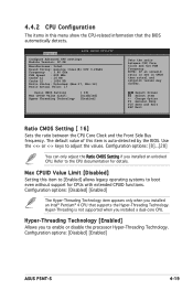
...Value: 17 Ratio CMOS Setting Max CPUID Value Limit: Hyper Threading Technology [ 16] [Disabled] [Enabled] Sets the ratio between the CPU Core Clock and the Front Side Bus frequency. Configuration options: [Disabled] [Enabled] The Hyper-Threading Technology item appears only ...Setting this menu show the CPU-related information that supports the Hyper-Threading Technology. Configuration options: [8]...[28] You can only adjust the Ratio CMOS Setting if you to adjust the values. Configuration options: [Disabled] [Enabled] ASUS P5MT-S 4-19 Hyper-Threading ...
...Value: 17 Ratio CMOS Setting Max CPUID Value Limit: Hyper Threading Technology [ 16] [Disabled] [Enabled] Sets the ratio between the CPU Core Clock and the Front Side Bus frequency. Configuration options: [Disabled] [Enabled] The Hyper-Threading Technology item appears only ...Setting this menu show the CPU-related information that supports the Hyper-Threading Technology. Configuration options: [8]...[28] You can only adjust the Ratio CMOS Setting if you to adjust the values. Configuration options: [Disabled] [Enabled] ASUS P5MT-S 4-19 Hyper-Threading ...
