

User Guide
Page 5
... Hardware Monitor 4-30 4.6 Server menu 4-32 Remote Access Configuration 4-32 4.7 Boot menu 4-34 4.7.1 Boot Device Priority 4-34 4.7.2 Boot Settings Configuration 4-35 4.7.3 Security 4-36 4.8 Exit menu 4-39 Chapter 5: RAID configuration 5.1 Setting up RAID 5-1 5.1.1 RAID definitions 5-1 5.1.2 Installing hard disk drives 5-2 5.1.3 Setting the RAID item in BIOS 5-2 5.1.4 RAID configuration utility 5-3 5.2 LSI Logic Embedded SATA RAID Setup Utility 5-4 5.2.1 Creating a RAID 0 or RAID 1 set 5-5 5.2.2 Creating a RAID 10 set 5-11 5.2.3 Adding or viewing a RAID...
... Hardware Monitor 4-30 4.6 Server menu 4-32 Remote Access Configuration 4-32 4.7 Boot menu 4-34 4.7.1 Boot Device Priority 4-34 4.7.2 Boot Settings Configuration 4-35 4.7.3 Security 4-36 4.8 Exit menu 4-39 Chapter 5: RAID configuration 5.1 Setting up RAID 5-1 5.1.1 RAID definitions 5-1 5.1.2 Installing hard disk drives 5-2 5.1.3 Setting the RAID item in BIOS 5-2 5.1.4 RAID configuration utility 5-3 5.2 LSI Logic Embedded SATA RAID Setup Utility 5-4 5.2.1 Creating a RAID 0 or RAID 1 set 5-5 5.2.2 Creating a RAID 10 set 5-11 5.2.3 Adding or viewing a RAID...

User Guide
Page 6
... set bootable 5-50 Chapter 6: Driver installation 6.1 RAID driver installation 6-1 6.1.1 Creating a RAID driver disk 6-1 6.1.2 Installing the RAID controller driver 6-2 6.2 LAN driver installation 6-11 6.2.1 Windows® 2000/2003 Server 6-11 6.2.2 Red Hat® Enterprise ver. 3.0 6-12 6.3 VGA driver installation 6-13 6.3.1 Windows® 2000 Server 6-13 6.3.2 Windows® 2003 Server 6-14 6.3.3 Red Hat® Enterprise ver. 3.0 6-14 6.4 Management applications and utilities installation 6-15 6.4.1 Running the support CD 6-15 6.4.2 Drivers menu 6-15 6.4.3 Management Software...
... set bootable 5-50 Chapter 6: Driver installation 6.1 RAID driver installation 6-1 6.1.1 Creating a RAID driver disk 6-1 6.1.2 Installing the RAID controller driver 6-2 6.2 LAN driver installation 6-11 6.2.1 Windows® 2000/2003 Server 6-11 6.2.2 Red Hat® Enterprise ver. 3.0 6-12 6.3 VGA driver installation 6-13 6.3.1 Windows® 2000 Server 6-13 6.3.2 Windows® 2003 Server 6-14 6.3.3 Red Hat® Enterprise ver. 3.0 6-14 6.4 Management applications and utilities installation 6-15 6.4.1 Running the support CD 6-15 6.4.2 Drivers menu 6-15 6.4.3 Management Software...

User Guide
Page 8
... add a device. • Before connecting or removing signal cables from the motherboard, ensure that all power cables from the existing system before the signal cables are connected. If possible, disconnect all power cables are unplugged. • Seek professional assistance before using , contact your retailer. Operation safety • Before installing the motherboard and adding devices on a stable surface. • If you are not damaged. Check local regulations for the devices...
... add a device. • Before connecting or removing signal cables from the motherboard, ensure that all power cables from the existing system before the signal cables are connected. If possible, disconnect all power cables are unplugged. • Seek professional assistance before using , contact your retailer. Operation safety • Before installing the motherboard and adding devices on a stable surface. • If you are not damaged. Check local regulations for the devices...

User Guide
Page 12
... VGA port 2 x LAN (RJ-45) ports 1 x Floppy disk drive connector 1 x IDE connector 4 x Serial ATA connectors 1 x Hard disk activity LED connector 1 x 68-pin SCSI connector 2 x Front fan connectors 2 x Rear fan connectors 2 x CPU fan connectors 1 x 24-pin ATX power connector 1 x 8-pin ATX 12 V power connector 1 x Power supply SMBUS connector 1 x Serial port (COM2) 1 x USB 2.0 connector for 2 additional USB 2.0 ports 1 x SMBus header for back-plane 1 x 20-1 pin auxiliary panel connector 1 x 20-1 pin system panel connector 1 x Serial port (COM2) connector 1 x ASUS server management (BMC) connector...
... VGA port 2 x LAN (RJ-45) ports 1 x Floppy disk drive connector 1 x IDE connector 4 x Serial ATA connectors 1 x Hard disk activity LED connector 1 x 68-pin SCSI connector 2 x Front fan connectors 2 x Rear fan connectors 2 x CPU fan connectors 1 x 24-pin ATX power connector 1 x 8-pin ATX 12 V power connector 1 x Power supply SMBUS connector 1 x Serial port (COM2) 1 x USB 2.0 connector for 2 additional USB 2.0 ports 1 x SMBus header for back-plane 1 x 20-1 pin auxiliary panel connector 1 x 20-1 pin system panel connector 1 x Serial port (COM2) connector 1 x ASUS server management (BMC) connector...
User Guide
Page 17
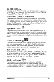
... RAID 0, RAID 1, RAID 0+1, and RAID 5 configuration for details. See pages 2-23 and 2-26 for SATA hard disk drives via the Intel® Matrix Storage Manager (under Windows Operating System) or the LSI Logic Embedded SATA RAID Setup Utility (no RAID 5). See page 2-25 and Chapter 5 for your storage devices. ASUS P5MT-S 1-3 The ZCR capability provides a cost-effective, high-performance, and added reliability for details. USB 2.0 technology The motherboard implements the Universal Serial Bus (USB...
... RAID 0, RAID 1, RAID 0+1, and RAID 5 configuration for details. See pages 2-23 and 2-26 for SATA hard disk drives via the Intel® Matrix Storage Manager (under Windows Operating System) or the LSI Logic Embedded SATA RAID Setup Utility (no RAID 5). See page 2-25 and Chapter 5 for your storage devices. ASUS P5MT-S 1-3 The ZCR capability provides a cost-effective, high-performance, and added reliability for details. USB 2.0 technology The motherboard implements the Universal Serial Bus (USB...
User Guide
Page 18
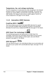
... the Winbond hardware monitor) to ensure quiet, cool, and efficient operation. Temperature, fan, and voltage monitoring The CPU temperature is monitored for timely failure detection. See page 4-31 for details. The ASIC monitors the voltage levels to buy a replacement ROM chip. This protection eliminates the need to ensure stable supply of ASUS Smart Fan technology. See page 4-5 for details. See page 4-35 for details. 1.3.2 Innovative ASUS features CrashFree BIOS 2 This...
... the Winbond hardware monitor) to ensure quiet, cool, and efficient operation. Temperature, fan, and voltage monitoring The CPU temperature is monitored for timely failure detection. See page 4-31 for details. The ASIC monitors the voltage levels to buy a replacement ROM chip. This protection eliminates the need to ensure stable supply of ASUS Smart Fan technology. See page 4-5 for details. See page 4-35 for details. 1.3.2 Innovative ASUS features CrashFree BIOS 2 This...
User Guide
Page 33
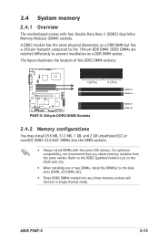
... compared to prevent installation on the ASUS web site. • When installing one or two DIMMs, install the DIMM(s) to the blue slots (DIMM_A2/DIMM_B2). • Three DDR2 DIMMs intalled into the DIMM sockets. • Always install DIMMs with four Double Data Rate 2 (DDR2) Dual Inline Memory Modules (DIMM) sockets. The figure illustrates the location of the DDR2 DIMM sockets: ® P5MT-S 128 Pins P5MT-S 240-pin DDR2...
... compared to prevent installation on the ASUS web site. • When installing one or two DIMMs, install the DIMM(s) to the blue slots (DIMM_A2/DIMM_B2). • Three DDR2 DIMMs intalled into the DIMM sockets. • Always install DIMMs with four Double Data Rate 2 (DDR2) Dual Inline Memory Modules (DIMM) sockets. The figure illustrates the location of the DDR2 DIMM sockets: ® P5MT-S 128 Pins P5MT-S 240-pin DDR2...
User Guide
Page 35
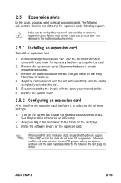
... intend to use . 4. Replace the system cover. 2.5.2 Configuring an expansion card After installing the expansion card, configure it and make the necessary hardware settings for details. Before installing the expansion card, read the documentation that they support. Assign an IRQ to the card. Failure to do not need to install expansion cards. Remove the system unit cover (if your motherboard is completely seated on the system and change the necessary BIOS settings, if any. 2.5 Expansion slots In...
... intend to use . 4. Replace the system cover. 2.5.2 Configuring an expansion card After installing the expansion card, configure it and make the necessary hardware settings for details. Before installing the expansion card, read the documentation that they support. Assign an IRQ to the card. Failure to do not need to install expansion cards. Remove the system unit cover (if your motherboard is completely seated on the system and change the necessary BIOS settings, if any. 2.5 Expansion slots In...

User Guide
Page 39
... using Windows 2000, you need to install Service Pack 4 to CPU, DRAM in slow refresh, power supply in sleep mode. otherwise, the system would not power up the system from S1 sleep mode (CPU stopped, DRAM refreshed, system running in low power mode) using the connected USB devices. ASUS P5MT-S 2-19 Set these jumpers to +5V to the CPU fan connectors (CPU_FAN1, CPU_FAN2). USB device wake-up (3-pin USBPW12, USBPW34) Set these jumpers to pins 1-2 if you are using a 3-pin fan cable...
... using Windows 2000, you need to install Service Pack 4 to CPU, DRAM in slow refresh, power supply in sleep mode. otherwise, the system would not power up the system from S1 sleep mode (CPU stopped, DRAM refreshed, system running in low power mode) using the connected USB devices. ASUS P5MT-S 2-19 Set these jumpers to +5V to the CPU fan connectors (CPU_FAN1, CPU_FAN2). USB device wake-up (3-pin USBPW12, USBPW34) Set these jumpers to pins 1-2 if you are using a 3-pin fan cable...

User Guide
Page 55
... monitor LED may have failed a power-on . External SCSI devices (starting with ATX power supplies, the system LED lights up or switch between orange and green after the system LED turns on test. Check the jumper settings and connections or call your monitor complies with a surge protector. 5. For systems with the last device on , hold down the key to the power connector at the back of the system chassis. 4. At power on the chain) c. AMI BIOS beep codes Beep Description...
... monitor LED may have failed a power-on . External SCSI devices (starting with ATX power supplies, the system LED lights up or switch between orange and green after the system LED turns on test. Check the jumper settings and connections or call your monitor complies with a surge protector. 5. For systems with the last device on , hold down the key to the power connector at the back of the system chassis. 4. At power on the chain) c. AMI BIOS beep codes Beep Description...
User Guide
Page 59
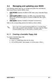
... the BIOS in Windows® environment.) Refer to manage and update the motherboard Basic Input/Output System (BIOS) setup. 1. ASUS AFUDOS (Updates the BIOS in DOS mode using the ASUS Update or AFUDOS utilities. 4.1.1 Creating a bootable floppy disk To create a bootable floppy disk: DOS environment a. ASUS P5MT-S 4-1 ASUS Update (Updates the BIOS in the future. Insert a 1.44MB floppy disk into the drive. Copy the original motherboard BIOS using a bootable floppy disk.) 2. Save a copy of the original motherboard BIOS...
... the BIOS in Windows® environment.) Refer to manage and update the motherboard Basic Input/Output System (BIOS) setup. 1. ASUS AFUDOS (Updates the BIOS in DOS mode using the ASUS Update or AFUDOS utilities. 4.1.1 Creating a bootable floppy disk To create a bootable floppy disk: DOS environment a. ASUS P5MT-S 4-1 ASUS Update (Updates the BIOS in the future. Insert a 1.44MB floppy disk into the drive. Copy the original motherboard BIOS using a bootable floppy disk.) 2. Save a copy of the original motherboard BIOS...
User Guide
Page 65
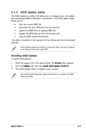
...; View the BIOS version information. The ASUS Update utility allows you to your system. Installing ASUS Update To install ASUS Update: 1. Place the support CD in the support CD that allows you update the BIOS using this utility. ASUS P5MT-S 4-7 Quit all Microsoft® Windows® applications before you to manage, save, and update the motherboard BIOS in Windows® environment. ASUS Update requires an Internet connection either through a network or an Internet Service Provider (ISP). Click the Utilities tab, then click Install ASUS Update VX...
...; View the BIOS version information. The ASUS Update utility allows you to your system. Installing ASUS Update To install ASUS Update: 1. Place the support CD in the support CD that allows you update the BIOS using this utility. ASUS P5MT-S 4-7 Quit all Microsoft® Windows® applications before you to manage, save, and update the motherboard BIOS in Windows® environment. ASUS Update requires an Internet connection either through a network or an Internet Service Provider (ISP). Click the Utilities tab, then click Install ASUS Update VX...
User Guide
Page 77
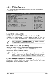
... you installed an Intel® Pentium® 4 CPU that the BIOS automatically detects. Change Option F1 General Help F10 Save and Exit ESC Exit Ratio CMOS Setting [ 16] Sets the ratio between CPU Core Clock and the FSB Frequency. The default value of this item to [Enabled] allows legacy operating systems to enable or disable the processor Hyper-Threading Technology. Advanced BIOS SETUP UTILITY Configure Advanced CPU settings Module Version...
... you installed an Intel® Pentium® 4 CPU that the BIOS automatically detects. Change Option F1 General Help F10 Save and Exit ESC Exit Ratio CMOS Setting [ 16] Sets the ratio between CPU Core Clock and the FSB Frequency. The default value of this item to [Enabled] allows legacy operating systems to enable or disable the processor Hyper-Threading Technology. Advanced BIOS SETUP UTILITY Configure Advanced CPU settings Module Version...

User Guide
Page 80
... using RedHat Linux Advanced Server 3.0 UP5/UP6 operating system. DRAM Frequency [Auto] Allows you are set according to the DRAM SPD (Serial Presence Detect). DISABLE: Do not allow remapping of overlapped PCI memory above the total physical memory. Configuration options: [Auto] [533 MHz] [667 MHz] Configure DRAM Timing by SPD [Enabled] [Auto] [Enabled] Boots Graphics Adapter Priority[PEG/PCI] PEG Port Configuration PEG Port [Auto] ENABLE...
... using RedHat Linux Advanced Server 3.0 UP5/UP6 operating system. DRAM Frequency [Auto] Allows you are set according to the DRAM SPD (Serial Presence Detect). DISABLE: Do not allow remapping of overlapped PCI memory above the total physical memory. Configuration options: [Auto] [533 MHz] [667 MHz] Configure DRAM Timing by SPD [Enabled] [Auto] [Enabled] Boots Graphics Adapter Priority[PEG/PCI] PEG Port Configuration PEG Port [Auto] ENABLE...

User Guide
Page 85
... APIC Support [Enabled] Allows you to change the settings for the ACPI and Advanced Power Management (APM) features. Configuration options: [Disabled] [Enabled] 4.5.1 APM Configuration APM Configuration Power Power Management/APM Video Power Down Mode Hard Disk Power Down Mode Standby Time Out Suspend Time Out Throttle Slow Clock Ratio BIOS SETUP UTILITY [Enabled] [Suspend] [Suspend] [Disabled] [Disabled] [50%] Enable or disable APM. Main Advanced Power ACPI APIC Support APM Configuration Hardware Monitor BIOS SETUP UTILITY Sever Boot Exit [Enabled] Include...
... APIC Support [Enabled] Allows you to change the settings for the ACPI and Advanced Power Management (APM) features. Configuration options: [Disabled] [Enabled] 4.5.1 APM Configuration APM Configuration Power Power Management/APM Video Power Down Mode Hard Disk Power Down Mode Standby Time Out Suspend Time Out Throttle Slow Clock Ratio BIOS SETUP UTILITY [Enabled] [Suspend] [Suspend] [Disabled] [Disabled] [50%] Enable or disable APM. Main Advanced Power ACPI APIC Support APM Configuration Hardware Monitor BIOS SETUP UTILITY Sever Boot Exit [Enabled] Include...

User Guide
Page 90
... then press to [Enabled]. 4-32 Chapter 4: BIOS setup BIOS SETUP UTILITY Server Configure Remote Access type and parameters Remote Access [Enabled] Serial port number Baudrate Flow Control Redirection After BIOS POST [COM1] [19200] [None] [Always] Terminal Type VT-UTFB Combo Key Support Meida Type [ANSI] [Disabled] [Serial] Select Remote Access type. Remote Access [Enabled] Enables or disables the remote access feature. Select Screen Select Item +- Remote Access Configuration The items in this menu allows you to customize the server features. Change Option F1 General Help...
... then press to [Enabled]. 4-32 Chapter 4: BIOS setup BIOS SETUP UTILITY Server Configure Remote Access type and parameters Remote Access [Enabled] Serial port number Baudrate Flow Control Redirection After BIOS POST [COM1] [19200] [None] [Always] Terminal Type VT-UTFB Combo Key Support Meida Type [ANSI] [Disabled] [Serial] Select Remote Access type. Remote Access [Enabled] Enables or disables the remote access feature. Select Screen Select Item +- Remote Access Configuration The items in this menu allows you to customize the server features. Change Option F1 General Help...
User Guide
Page 94
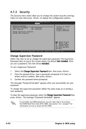
... The Security menu items allow you to change password. BIOS SETUP UTILITY Boot Security Settings Supervisor Password User Password : Not Installed : Not Installed Change Supervisor Password Change User Password to change the system security settings. To change the supervisor password. If you successfully set or change the supervisor password, follow the same steps as in setting a user password. again to display the configuration options. The Supervisor Password item on how to set your BIOS password, you set a Supervisor Password: 1. To clear the supervisor...
... The Security menu items allow you to change password. BIOS SETUP UTILITY Boot Security Settings Supervisor Password User Password : Not Installed : Not Installed Change Supervisor Password Change User Password to change the system security settings. To change the supervisor password. If you successfully set or change the supervisor password, follow the same steps as in setting a user password. again to display the configuration options. The Supervisor Password item on how to set your BIOS password, you set a Supervisor Password: 1. To clear the supervisor...

User Guide
Page 101
... surviving drive as a RAID set , copy first the RAID driver from one drive fails, the disk array management software directs all the benefits of both RAID 0 and RAID 1 configurations. RAID 1 (Data mirroring) copies and maintains an identical image of data from the support CD to a second drive. JBOD (Spanning) stands for this setup. ASUS P5MT-S 5-1 Use four new hard disk drives or use an existing drive and a new drive for this setup. Two hard disks perform...
... surviving drive as a RAID set , copy first the RAID driver from one drive fails, the disk array management software directs all the benefits of both RAID 0 and RAID 1 configurations. RAID 1 (Data mirroring) copies and maintains an identical image of data from the support CD to a second drive. JBOD (Spanning) stands for this setup. ASUS P5MT-S 5-1 Use four new hard disk drives or use an existing drive and a new drive for this setup. Two hard disks perform...
User Guide
Page 102
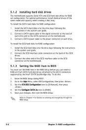
... the instructions in the system user guide. 2. To install the SATA hard disks for RAID configuration: 1. Set the Configure SATA As item to [RAID]. 5. For optimal performance, install identical drives of the SCSI interface cable to the SCSI connector on entering and navigating through the BIOS Setup. 5-2 Chapter 5: RAID configuration Save your changes, then exit the BIOS Setup. Enter the BIOS Setup during POST. 2. 5.1.2 Installing hard disk drives The motherboard supports Serial ATA and SCSI hard disk drives for RAID set from SATA hard disk drives attached...
... the instructions in the system user guide. 2. To install the SATA hard disks for RAID configuration: 1. Set the Configure SATA As item to [RAID]. 5. For optimal performance, install identical drives of the SCSI interface cable to the SCSI connector on entering and navigating through the BIOS Setup. 5-2 Chapter 5: RAID configuration Save your changes, then exit the BIOS Setup. Enter the BIOS Setup during POST. 2. 5.1.2 Installing hard disk drives The motherboard supports Serial ATA and SCSI hard disk drives for RAID set from SATA hard disk drives attached...
User Guide
Page 169
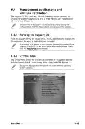
... the drivers, management applications, and utilities that you can install to run the CD. 6.4.2 Drivers menu The Drivers menu shows the available device drivers if the system detects installed devices. ASUS P5MT-S 6-15 Doubleclick the ASSETUP.EXE to avail all motherboard features. If Autorun is enabled in your computer. Visit the ASUS website (www.asus.com) for updates. 6.4.1 Running the support CD Place the support CD to activate the devices. The CD automatically displays the Drivers menu if...
... the drivers, management applications, and utilities that you can install to run the CD. 6.4.2 Drivers menu The Drivers menu shows the available device drivers if the system detects installed devices. ASUS P5MT-S 6-15 Doubleclick the ASSETUP.EXE to avail all motherboard features. If Autorun is enabled in your computer. Visit the ASUS website (www.asus.com) for updates. 6.4.1 Running the support CD Place the support CD to activate the devices. The CD automatically displays the Drivers menu if...


