
User Manual
Page 1
P5K SE/EPU Motherboard
P5K SE/EPU Motherboard

User Manual
Page 3
......vii Safety information viii About this guide ix P5K SE/EPU specifications summary xi Chapter 1: Product introduction 1.1 Welcome 1-1 1.2 Package contents 1-1 1.3 Special features 1-2 1.3.1 Product highlights 1-2 1.3.2 ASUS AI Lifestyle features 1-4 1.3.3 ASUS Stylish features 1-5 1.3.4 ASUS Intelligent Overclocking features 1-6 Chapter 2: Hardware information 2.1 Before you proceed 2-1 2.2 Motherboard overview 2-2 2.2.1 Placement direction 2-2 2.2.2 Screw holes 2-2 2.2.3 Motherboard layout 2-3 2.2.4 Layout contents 2-4 2.3 Central Processing Unit (CPU 2-6 2.3.1 Installing...
......vii Safety information viii About this guide ix P5K SE/EPU specifications summary xi Chapter 1: Product introduction 1.1 Welcome 1-1 1.2 Package contents 1-1 1.3 Special features 1-2 1.3.1 Product highlights 1-2 1.3.2 ASUS AI Lifestyle features 1-4 1.3.3 ASUS Stylish features 1-5 1.3.4 ASUS Intelligent Overclocking features 1-6 Chapter 2: Hardware information 2.1 Before you proceed 2-1 2.2 Motherboard overview 2-2 2.2.1 Placement direction 2-2 2.2.2 Screw holes 2-2 2.2.3 Motherboard layout 2-3 2.2.4 Layout contents 2-4 2.3 Central Processing Unit (CPU 2-6 2.3.1 Installing...

User Manual
Page 15
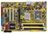
... , check the items in the long line of the above items is damaged or missing, contact your motherboard package for buying an ASUS® P5K SE/EPU motherboard! Before you for the following items. Motherboard Cables Accessories Application CD Documentation ASUS P5K SE/EPU 2 x Serial ATA signal cable 1 x Serial ATA power cable 1 x Ultra DMA 133/100/66 cable 1 x Floppy disk drive...
... , check the items in the long line of the above items is damaged or missing, contact your motherboard package for buying an ASUS® P5K SE/EPU motherboard! Before you for the following items. Motherboard Cables Accessories Application CD Documentation ASUS P5K SE/EPU 2 x Serial ATA signal cable 1 x Serial ATA power cable 1 x Ultra DMA 133/100/66 cable 1 x Floppy disk drive...

User Manual
Page 17
...quality. The external SATA port located at the back I/O provides smart setup and hot-plug functions. S/PDIF digital sound ready This motherboard provides convenient connectivity to external home theater audio systems via coaxial and optical S/PDIF-out (SONY-PHILIPS Digital Interface) jacks.It ... bandwidth for details. See pages 2-24 and 2-25 for high-speed data retrieval and saves. ASUS P5K SE/EPU 1-3 Serial ATA 3.0 Gb/s technology and SATA-On-The-Go This motherboard supports the next-generation hard drives based on the headphone while playing multi-channel network games. You...
...quality. The external SATA port located at the back I/O provides smart setup and hot-plug functions. S/PDIF digital sound ready This motherboard provides convenient connectivity to external home theater audio systems via coaxial and optical S/PDIF-out (SONY-PHILIPS Digital Interface) jacks.It ... bandwidth for details. See pages 2-24 and 2-25 for high-speed data retrieval and saves. ASUS P5K SE/EPU 1-3 Serial ATA 3.0 Gb/s technology and SATA-On-The-Go This motherboard supports the next-generation hard drives based on the headphone while playing multi-channel network games. You...

User Manual
Page 19
... details. See pages 5-8 and 5-9 for details. See page 2-35 for details. Profile The motherboard features the ASUS O.C. This unique module eliminates the trouble of the computer. 1.3.3 ASUS Stylish features ASUS MyLogo2™ This feature allows you to convert your favorite photo into a 256-color boot logo... 2 is a user-friendly BIOS update utility. Simply press the predefined hotkey to conveniently store or load multiple BIOS settings. ASUS P5K SE/EPU 1-5 Update your BIOS easily without entering the OS. Profile that aren't. Smart Support CD It provides a checklist to allow ...
... details. See pages 5-8 and 5-9 for details. See page 2-35 for details. Profile The motherboard features the ASUS O.C. This unique module eliminates the trouble of the computer. 1.3.3 ASUS Stylish features ASUS MyLogo2™ This feature allows you to convert your favorite photo into a 256-color boot logo... 2 is a user-friendly BIOS update utility. Simply press the predefined hotkey to conveniently store or load multiple BIOS settings. ASUS P5K SE/EPU 1-5 Update your BIOS easily without entering the OS. Profile that aren't. Smart Support CD It provides a checklist to allow ...

User Manual
Page 22
Chapter summary 2 2.1 Before you proceed 2-1 2.2 Motherboard overview 2-2 2.3 Central Processing Unit (CPU 2-6 2.4 System memory 2-13 2.5 Expansion slots 2-19 2.6 Jumpers 2-22 2.7 Connectors 2-24 ASUS P5K SE/EPU
Chapter summary 2 2.1 Before you proceed 2-1 2.2 Motherboard overview 2-2 2.3 Central Processing Unit (CPU 2-6 2.4 System memory 2-13 2.5 Expansion slots 2-19 2.6 Jumpers 2-22 2.7 Connectors 2-24 ASUS P5K SE/EPU

User Manual
Page 23
... the ATX power supply is switched off mode. The illustration below shows the location of the following precautions before you install motherboard components or change any motherboard settings. • Unplug the power cord from the wall socket before touching any component. • Use a grounded wrist... is detached from the power supply. P5K SE/EPU SB_PWR ® ON Standby Power P5K SE/EPU Onboard LED OFF Powered Off ASUS P5K SE/EPU 2-1 This is ON, in sleep mode, or in the bag that came with a standby power LED that lights up to the motherboard, peripherals, and/or components. 2.1...
... the ATX power supply is switched off mode. The illustration below shows the location of the following precautions before you install motherboard components or change any motherboard settings. • Unplug the power cord from the wall socket before touching any component. • Use a grounded wrist... is detached from the power supply. P5K SE/EPU SB_PWR ® ON Standby Power P5K SE/EPU Onboard LED OFF Powered Off ASUS P5K SE/EPU 2-1 This is ON, in sleep mode, or in the bag that came with a standby power LED that lights up to the motherboard, peripherals, and/or components. 2.1...

User Manual
Page 24
... into the holes indicated by circles to secure the motherboard to do so can damage the motherboard. Failure to the chassis. Place this side towards the rear of your chassis to ensure that you install the motherboard, study the configuration of the chassis ® P5K SE/EPU 2-2 Chapter 2: Hardware information The edge with external ports goes...
... into the holes indicated by circles to secure the motherboard to do so can damage the motherboard. Failure to the chassis. Place this side towards the rear of your chassis to ensure that you install the motherboard, study the configuration of the chassis ® P5K SE/EPU 2-2 Chapter 2: Hardware information The edge with external ports goes...

User Manual
Page 25
ASUS P5K SE/EPU 2-3 P5K SE/EPU DDR2 DIMM_A1 (64 bit,240-pin module) DDR2 DIMM_A2 (64 bit,240-pin module) DDR2 DIMM_B1 (64 bit,240-pin module) DDR2 DIMM_B2 (64 bit,240-pin module) EATXPWR 30.5cm (12.0in) 2.2.3 Motherboard layout 19.3cm (7.6in) KB_USB56 PS2_USBPW ATX12V SPDIF_O1 USB34 ESATA LGA775 EPU CPU_FAN LAN1_USB12 AUDIO Intel® P35 USB78...
ASUS P5K SE/EPU 2-3 P5K SE/EPU DDR2 DIMM_A1 (64 bit,240-pin module) DDR2 DIMM_A2 (64 bit,240-pin module) DDR2 DIMM_B1 (64 bit,240-pin module) DDR2 DIMM_B2 (64 bit,240-pin module) EATXPWR 30.5cm (12.0in) 2.2.3 Motherboard layout 19.3cm (7.6in) KB_USB56 PS2_USBPW ATX12V SPDIF_O1 USB34 ESATA LGA775 EPU CPU_FAN LAN1_USB12 AUDIO Intel® P35 USB78...

User Manual
Page 29
... face you and the load lever is on the motherboard. P5K SE/EPU ® P5K SE/EPU CPU Socket 775 Before installing the CPU, make sure that the socket box is released from the retention tab. To prevent damage to the left . 2. 2.3.1 Installing the CPU To install a CPU: 1. ASUS P5K SE/EPU 2-7 Press the load lever with your left (B) until it...
... face you and the load lever is on the motherboard. P5K SE/EPU ® P5K SE/EPU CPU Socket 775 Before installing the CPU, make sure that the socket box is released from the retention tab. To prevent damage to the left . 2. 2.3.1 Installing the CPU To install a CPU: 1. ASUS P5K SE/EPU 2-7 Press the load lever with your left (B) until it...

User Manual
Page 31
Place the heatsink on the motherboard. Narrow end of the groove Motherboard hole Fastener Make sure to orient each fastener with the narrow end of the installed CPU, making sure that you have properly applied Thermal Interface ... fasteners match the holes on top of the groove pointing outward. (The photo shows the groove shaded for emphasis.) ASUS P5K SE/EPU 2-9 Orient the heatsink and fan assembly such that you have installed the motherboard to the chassis before you buy a CPU separately, make sure that you use only Intel®‑certified multi...
Place the heatsink on the motherboard. Narrow end of the groove Motherboard hole Fastener Make sure to orient each fastener with the narrow end of the installed CPU, making sure that you have properly applied Thermal Interface ... fasteners match the holes on top of the groove pointing outward. (The photo shows the groove shaded for emphasis.) ASUS P5K SE/EPU 2-9 Orient the heatsink and fan assembly such that you have installed the motherboard to the chassis before you buy a CPU separately, make sure that you use only Intel®‑certified multi...

User Manual
Page 32
Connect the CPU fan cable to secure the heatsink and fan assembly in place. Push down two fasteners at a time in a diagonal sequence to the connector on the motherboard labeled CPU_FAN. CPU_FAN P5K SE/EPU GND CPU FAN PWR CPU FAN IN CPU FAN PWM ® P5K SE/EPU CPU fan connector Do not forget to plug this connector. 2-10 Chapter 2: Hardware information B A A A B B B A 3. Hardware monitoring errors can occur if you fail to connect the CPU fan connector! 2.
Connect the CPU fan cable to secure the heatsink and fan assembly in place. Push down two fasteners at a time in a diagonal sequence to the connector on the motherboard labeled CPU_FAN. CPU_FAN P5K SE/EPU GND CPU FAN PWR CPU FAN IN CPU FAN PWM ® P5K SE/EPU CPU fan connector Do not forget to plug this connector. 2-10 Chapter 2: Hardware information B A A A B B B A 3. Hardware monitoring errors can occur if you fail to connect the CPU fan connector! 2.

User Manual
Page 33
Pull up two fasteners at a time in a diagonal sequence to disengage the heatsink and fan assembly B from the motherboard. A A B A B B A 4. ASUS P5K SE/EPU 2-11 Carefully remove the heatsink and fan assembly from the motherboard. Rotate each fastener counterclockwise. 3. Disconnect the CPU fan cable from the connector on the motherboard. 2. 2.3.3 Uninstalling the CPU heatsink and fan To uninstall the CPU heatsink and fan: 1.
Pull up two fasteners at a time in a diagonal sequence to disengage the heatsink and fan assembly B from the motherboard. A A B A B B A 4. ASUS P5K SE/EPU 2-11 Carefully remove the heatsink and fan assembly from the motherboard. Rotate each fastener counterclockwise. 3. Disconnect the CPU fan cable from the connector on the motherboard. 2. 2.3.3 Uninstalling the CPU heatsink and fan To uninstall the CPU heatsink and fan: 1.

User Manual
Page 35
2.4 System memory 2.4.1 Overview The motherboard comes with four Double Data Rate 2 (DDR2) Dual Inline Memory Modules (DIMM) sockets. The figure illustrates the location of the DDR2 DIMM sockets: P5K SE/EPU DIMM_A1 DIMM_A2 DIMM_B1 DIMM_B2 ® P5K SE/EPU 240-pin DDR2 DIMM sockets Channel Channel A Channel B Sockets DIMM_A1 and DIMM_B1 DIMM_A2 and DIMM_B2 ASUS P5K SE/EPU 2-13
2.4 System memory 2.4.1 Overview The motherboard comes with four Double Data Rate 2 (DDR2) Dual Inline Memory Modules (DIMM) sockets. The figure illustrates the location of the DDR2 DIMM sockets: P5K SE/EPU DIMM_A1 DIMM_A2 DIMM_B1 DIMM_B2 ® P5K SE/EPU 240-pin DDR2 DIMM sockets Channel Channel A Channel B Sockets DIMM_A1 and DIMM_B1 DIMM_A2 and DIMM_B2 ASUS P5K SE/EPU 2-13

User Manual
Page 37
... SPD is DDR2-800, make sure that you set the DRAM Frequency item in BIOS to [DDR2-1066MHz]. See section 4.4.1 Jumperfree Configuration for details. ASUS P5K SE/EPU 2-15 P5K SE/EPU Motherboard Qualified Vendors Lists (QVL) DDR2-1066 MHz capability Size 512 512 512 1024 1024 1024 1024 1024 1024 Vendor OCZ Crucial Kingston Kingston CORSAIR CORSAIR...
... SPD is DDR2-800, make sure that you set the DRAM Frequency item in BIOS to [DDR2-1066MHz]. See section 4.4.1 Jumperfree Configuration for details. ASUS P5K SE/EPU 2-15 P5K SE/EPU Motherboard Qualified Vendors Lists (QVL) DDR2-1066 MHz capability Size 512 512 512 1024 1024 1024 1024 1024 1024 Vendor OCZ Crucial Kingston Kingston CORSAIR CORSAIR...

User Manual
Page 39
P5K SE/EPU Motherboard Qualified Vendors Lists (QVL) DDR2-667MHz capability Size Vendor Chip No. Visit the ASUS website for the latest DDR2-1066/800/667MHz QVL. CL 512MB 512MB 1024MB 256MB 512MB 1024MB 256MB 1024MB 256MB 2048MB 512MB 512MB 1024MB SAMSUNG SAMSUNG ... pair of Dual-channel memory configuration. • C*: Supports 4 modules inserted into both the yellow and black slots as two pairs of Dual-channel memory configuration. ASUS P5K SE/EPU 2-17
P5K SE/EPU Motherboard Qualified Vendors Lists (QVL) DDR2-667MHz capability Size Vendor Chip No. Visit the ASUS website for the latest DDR2-1066/800/667MHz QVL. CL 512MB 512MB 1024MB 256MB 512MB 1024MB 256MB 1024MB 256MB 2048MB 512MB 512MB 1024MB SAMSUNG SAMSUNG ... pair of Dual-channel memory configuration. • C*: Supports 4 modules inserted into both the yellow and black slots as two pairs of Dual-channel memory configuration. ASUS P5K SE/EPU 2-17
User Manual
Page 41
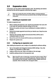
... making the system unstable and the card inoperable. Refer to do not need to the chassis with it by adjusting the software settings. 1. ASUS P5K SE/EPU 2-19 Make sure to use . 4. Before installing the expansion card, read the documentation that the cards do so may need IRQ assignments....install expansion cards. Keep the screw for the card. 2. 2.5 Expansion slots In the future, you may cause you physical injury and damage motherboard components. 2.5.1 Installing an expansion card To install an expansion card: 1. Assign an IRQ to the tables on the system and change the ...
... making the system unstable and the card inoperable. Refer to do not need to the chassis with it by adjusting the software settings. 1. ASUS P5K SE/EPU 2-19 Make sure to use . 4. Before installing the expansion card, read the documentation that the cards do so may need IRQ assignments....install expansion cards. Keep the screw for the card. 2. 2.5 Expansion slots In the future, you may cause you physical injury and damage motherboard components. 2.5.1 Installing an expansion card To install an expansion card: 1. Assign an IRQ to the tables on the system and change the ...

User Manual
Page 43
... one PCI Express x16 graphics card that complies with the PCI Express specifications. ASUS P5K SE/EPU 2-21 The figure shows a LAN card installed on a PCI slot. 2.5.5 PCI Express x1 slots This motherboard supports PCI Express x1 network cards, SCSI cards and other cards that comply with the PCI Express specifications. 2.5.4 PCI slots The PCI...
... one PCI Express x16 graphics card that complies with the PCI Express specifications. ASUS P5K SE/EPU 2-21 The figure shows a LAN card installed on a PCI slot. 2.5.5 PCI Express x1 slots This motherboard supports PCI Express x1 network cards, SCSI cards and other cards that comply with the PCI Express specifications. 2.5.4 PCI slots The PCI...

User Manual
Page 49
...the motherboard's IDE connector, then select one of device(s) Master Slave Master Slave Cable connector Black Black Gray Black or gray • Pin 20 on the IDE connector is removed to match the covered hole on each Ultra DMA 133/100/66 signal cable: blue, black, and gray. P5K SE/EPU ... Master Slave Mode of the following modes to PIN 1. If any device jumper is for Ultra DMA 133/100/66 IDE devices. P5K SE/EPU IDE connector PIN 1 ASUS P5K SE/EPU 2-27 2. This prevents incorrect insertion when you connect the IDE cable. • Use the 80-conductor IDE cable for the Ultra...
...the motherboard's IDE connector, then select one of device(s) Master Slave Master Slave Cable connector Black Black Gray Black or gray • Pin 20 on the IDE connector is removed to match the covered hole on each Ultra DMA 133/100/66 signal cable: blue, black, and gray. P5K SE/EPU ... Master Slave Mode of the following modes to PIN 1. If any device jumper is for Ultra DMA 133/100/66 IDE devices. P5K SE/EPU IDE connector PIN 1 ASUS P5K SE/EPU 2-27 2. This prevents incorrect insertion when you connect the IDE cable. • Use the 80-conductor IDE cable for the Ultra...
User Manual
Page 72
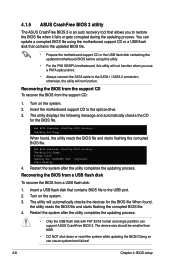
... flash disk that contains the updated BIOS file. • Prepare the motherboard support CD or the USB flash disk containing the updated motherboard BIOS before using this utility. • For the P5K SE/EPU motherboard, this utility will automatically checks the devices for the BIOS file. Floppy... and starts flashing the corrupted BIOS file. 4. Bad BIOS checksum. Bad BIOS checksum. Starting BIOS recovery... Completed. 4.1.5 ASUS CrashFree BIOS 3 utility The ASUS CrashFree BIOS 3 is an auto recovery tool that allows you use a PATA optical drive. • Always connect the ...
... flash disk that contains the updated BIOS file. • Prepare the motherboard support CD or the USB flash disk containing the updated motherboard BIOS before using this utility. • For the P5K SE/EPU motherboard, this utility will automatically checks the devices for the BIOS file. Floppy... and starts flashing the corrupted BIOS file. 4. Bad BIOS checksum. Bad BIOS checksum. Starting BIOS recovery... Completed. 4.1.5 ASUS CrashFree BIOS 3 utility The ASUS CrashFree BIOS 3 is an auto recovery tool that allows you use a PATA optical drive. • Always connect the ...


