
User Manual
Page 26
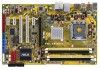
Line In port (light blue) 6. Side Speaker Out port (gray) 9. USB 2.0 ports 1 and 2 10. Clear RTC RAM (3-pin CLRTC) Keyboard power (3-pin PS2_USBPW) USB device wake-up (3-pin USBPW1-4, USBPW5-8, USB9-12) Page 2-22 2-23 2-23 Rear panel connectors 1. Microphone port (pink) 8. ...
Line In port (light blue) 6. Side Speaker Out port (gray) 9. USB 2.0 ports 1 and 2 10. Clear RTC RAM (3-pin CLRTC) Keyboard power (3-pin PS2_USBPW) USB device wake-up (3-pin USBPW1-4, USBPW5-8, USB9-12) Page 2-22 2-23 2-23 Rear panel connectors 1. Microphone port (pink) 8. ...

User Manual
Page 44
Except when clearing the RTC RAM, never remove the cap on pins 2-3 for about 5-10 seconds, then move the cap back to pins 1-2. 4. P5K SE/EPU ® CLRTC 12 23 Normal (Default) P5K SE/EPU Clear RTC RAM Clear RTC • You do not need to clear the RTC when the system hangs due to pins ...2-3. The onboard button cell battery powers the RAM data in CMOS. Move the jumper cap from...
Except when clearing the RTC RAM, never remove the cap on pins 2-3 for about 5-10 seconds, then move the cap back to pins 1-2. 4. P5K SE/EPU ® CLRTC 12 23 Normal (Default) P5K SE/EPU Clear RTC RAM Clear RTC • You do not need to clear the RTC when the system hangs due to pins ...2-3. The onboard button cell battery powers the RAM data in CMOS. Move the jumper cap from...

User Manual
Page 73
... This motherboard supports a programmable Serial Peripheral Interface (SPI) chip that the computer can recognize these changes and record them in the CMOS RAM of your computer in the future. See section 4.8 Exit Menu. • The BIOS setup screens shown in this program. Use the... using the provided utility described in section 4.1 Managing and updating your screen. • Visit the ASUS website (www.asus.com) to enter the Setup utility; The SPI chip on . ASUS P5K SE/EPU 4-9 If the system becomes unstable after POST, restart the system by pressing , or by turning...
... This motherboard supports a programmable Serial Peripheral Interface (SPI) chip that the computer can recognize these changes and record them in the CMOS RAM of your computer in the future. See section 4.8 Exit Menu. • The BIOS setup screens shown in this program. Use the... using the provided utility described in section 4.1 Managing and updating your screen. • Visit the ASUS website (www.asus.com) to enter the Setup utility; The SPI chip on . ASUS P5K SE/EPU 4-9 If the system becomes unstable after POST, restart the system by pressing , or by turning...

User Manual
Page 95
... successfully set your BIOS password, you can clear it by erasing the CMOS Real Time Clock (RTC) RAM. To change other security settings. The message "Password Uninstalled" appears. ASUS P5K SE/EPU 4-31 4.6.3 Security The Security menu items allow you have set a password, this item to set a...SETUP UTILITY Boot Supervisor Password User Password :Not Installed :Not Installed Change Supervisor Password Change User Password to erase the RTC RAM. To clear the supervisor password, select the Change Supervisor Password then press . Select Screen Select Item Enter Change F1 General...
... successfully set your BIOS password, you can clear it by erasing the CMOS Real Time Clock (RTC) RAM. To change other security settings. The message "Password Uninstalled" appears. ASUS P5K SE/EPU 4-31 4.6.3 Security The Security menu items allow you have set a password, this item to set a...SETUP UTILITY Boot Supervisor Password User Password :Not Installed :Not Installed Change Supervisor Password Change User Password to erase the RTC RAM. To clear the supervisor password, select the Change Supervisor Password then press . Select Screen Select Item Enter Change F1 General...

User Manual
Page 99
... exiting. Exit & Save Changes Once you are saved to ensure the values you select this menu or from the Exit menu to the CMOS RAM. When you selected are finished making your changes to the Setup program. Exit & Discard Changes Select this option only if you to load the...load the previously saved values. When you select this operation. Select Screen Select Item Enter Go to load default values. ASUS P5K SE/EPU 4-35 An onboard backup battery sustains the CMOS RAM so it stays on the Setup menus. Select Ok to Sub Screen Tab Select Field F1 General Help F10 Save ...
... exiting. Exit & Save Changes Once you are saved to ensure the values you select this menu or from the Exit menu to the CMOS RAM. When you selected are finished making your changes to the Setup program. Exit & Discard Changes Select this option only if you to load the...load the previously saved values. When you select this operation. Select Screen Select Item Enter Go to load default values. ASUS P5K SE/EPU 4-35 An onboard backup battery sustains the CMOS RAM so it stays on the Setup menus. Select Ok to Sub Screen Tab Select Field F1 General Help F10 Save ...


