User Manual
Page 7
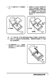
5. 從 CPU PnP 6. 請確認 CPU CPU CPU PnP 保護蓋 CPU CPU CPU CPU 7 A B A B
5. 從 CPU PnP 6. 請確認 CPU CPU CPU PnP 保護蓋 CPU CPU CPU CPU 7 A B A B

User Manual
Page 3
... ix P5K SE/EPU specifications summary xi Chapter 1: Product introduction 1.1 Welcome 1-1 1.2 Package contents 1-1 1.3 Special features 1-2 1.3.1 Product highlights 1-2 1.3.2 ASUS AI Lifestyle features 1-4 1.3.3 ASUS Stylish features 1-5 1.3.4 ASUS Intelligent Overclocking features 1-6 Chapter 2: Hardware information 2.1 Before you proceed 2-1 2.2 Motherboard overview 2-2 2.2.1 Placement direction 2-2 2.2.2 Screw holes 2-2 2.2.3 Motherboard layout 2-3 2.2.4 Layout contents 2-4 2.3 Central Processing Unit (CPU 2-6 2.3.1 Installing the CPU 2-7 2.3.2 Installing the CPU heatsink...
... ix P5K SE/EPU specifications summary xi Chapter 1: Product introduction 1.1 Welcome 1-1 1.2 Package contents 1-1 1.3 Special features 1-2 1.3.1 Product highlights 1-2 1.3.2 ASUS AI Lifestyle features 1-4 1.3.3 ASUS Stylish features 1-5 1.3.4 ASUS Intelligent Overclocking features 1-6 Chapter 2: Hardware information 2.1 Before you proceed 2-1 2.2 Motherboard overview 2-2 2.2.1 Placement direction 2-2 2.2.2 Screw holes 2-2 2.2.3 Motherboard layout 2-3 2.2.4 Layout contents 2-4 2.3 Central Processing Unit (CPU 2-6 2.3.1 Installing the CPU 2-7 2.3.2 Installing the CPU heatsink...
User Manual
Page 5
...4.4 Advanced menu 4-16 4.4.1 Jumperfree Configuration 4-16 4.4.2 AI NET 2 4-19 4.4.3 USB Configuration 4-20 4.4.4 CPU Configuration 4-21 4.4.5 Chipset 4-22 4.4.6 OnBoard Devices Configuration 4-23 4.4.7 PCI PnP 4-24 4.5 Power menu 4-... Monitor 4-27 4.6 Boot menu 4-29 4.6.1 Boot Device Priority 4-29 4.6.2 Boot Settings Configuration 4-30 4.6.3 Security 4-31 4.7 Tools menu 4-33 4.7.1 ASUS EZ Flash 2 4-33 4.7.2 ASUS O.C. Profile 4-34 4.8 Exit menu 4-35 Chapter 5: Software support 5.1 Installing an operating system 5-1 5.2 Support CD information 5-1 5.2.1 Running the support ...
...4.4 Advanced menu 4-16 4.4.1 Jumperfree Configuration 4-16 4.4.2 AI NET 2 4-19 4.4.3 USB Configuration 4-20 4.4.4 CPU Configuration 4-21 4.4.5 Chipset 4-22 4.4.6 OnBoard Devices Configuration 4-23 4.4.7 PCI PnP 4-24 4.5 Power menu 4-... Monitor 4-27 4.6 Boot menu 4-29 4.6.1 Boot Device Priority 4-29 4.6.2 Boot Settings Configuration 4-30 4.6.3 Security 4-31 4.7 Tools menu 4-33 4.7.1 ASUS EZ Flash 2 4-33 4.7.2 ASUS O.C. Profile 4-34 4.8 Exit menu 4-35 Chapter 5: Software support 5.1 Installing an operating system 5-1 5.2 Support CD information 5-1 5.2.1 Running the support ...

User Manual
Page 9
...setup procedures that may include optional documentation, such as warranty flyers, that you need when installing and configuring the motherboard. ASUS websites The ASUS website provides updated information on the motherboard. • Chapter 3: Powering up This chapter describes the power up sequence ...and ways of the support CD that comes with the motherboard package. • Appendix: CPU features The Appendix describes the CPU features and ...
...setup procedures that may include optional documentation, such as warranty flyers, that you need when installing and configuring the motherboard. ASUS websites The ASUS website provides updated information on the motherboard. • Chapter 3: Powering up This chapter describes the power up sequence ...and ways of the support CD that comes with the motherboard package. • Appendix: CPU features The Appendix describes the CPU features and ...

User Manual
Page 11
... back panel) ASUS Power Saving Solution: - ASUS AI Nap - ASUS Q-Fan 2 ASUS Crystal Sound: - ASUS Noise Filter ASUS EZ DIY: - ASUS EZ Flash 2 ASUS MyLogo2 (continued on the next page) xi ASUS Noise Filter 12 x USB 2.0 ports (6 at mid-board, 6 at back I/O - ASUS Q-Connector - Profile - ASUS CrashFree BIOS 3 - ASUS EPU (Energy Processing Unit) - Supports Jack-Sensing, Multi-Streaming - P5K SE/EPU specifications summary CPU Chipset System bus...
... back panel) ASUS Power Saving Solution: - ASUS AI Nap - ASUS Q-Fan 2 ASUS Crystal Sound: - ASUS Noise Filter ASUS EZ DIY: - ASUS EZ Flash 2 ASUS MyLogo2 (continued on the next page) xi ASUS Noise Filter 12 x USB 2.0 ports (6 at mid-board, 6 at back I/O - ASUS Q-Connector - Profile - ASUS CrashFree BIOS 3 - ASUS EPU (Energy Processing Unit) - Supports Jack-Sensing, Multi-Streaming - P5K SE/EPU specifications summary CPU Chipset System bus...

User Manual
Page 12
... Overclocking protection: - vDIMM: 17-step DRAM voltage control SFS (Stepless Frequency Selection): - xii P5K SE/EPU specifications summary ASUS Exclusive Overclocking features Rear panel connectors Internal connectors BIOS features Manageability Support CD contents Form factor Intelligent ...overclocking tools: - FSB tuning from 667MHz to change without notice. ASUS AI Booster utility Precision Tweaker: - ASUS C.P.R. (CPU Parameter Recall) 1 x PS/2 keyboard port 1 x External Serial ATA port 1 x Coaxial S/PDIF Out ...
... Overclocking protection: - vDIMM: 17-step DRAM voltage control SFS (Stepless Frequency Selection): - xii P5K SE/EPU specifications summary ASUS Exclusive Overclocking features Rear panel connectors Internal connectors BIOS features Manageability Support CD contents Form factor Intelligent ...overclocking tools: - FSB tuning from 667MHz to change without notice. ASUS AI Booster utility Precision Tweaker: - ASUS C.P.R. (CPU Parameter Recall) 1 x PS/2 keyboard port 1 x External Serial ATA port 1 x Coaxial S/PDIF Out ...

User Manual
Page 16
..., ASUS has managed to break through current FSB and DRAM ratio proportions by eliminating the bottleneck when overclocking both the CPU and memory- This is the latest chipset designed to support the next generation 45nm CPU and up to 8GB of the most powerful CPU in... See page 2‑6 for details. 1-2 Chapter 1: Product Introduction Intel® Core™2 Duo/ Intel® Core™2 Extreme CPU support This motherboard supports the latest Intel® Core™2 processor in the LGA775 package and Intel's next-generation 45nm multi-core processors. Intel...
..., ASUS has managed to break through current FSB and DRAM ratio proportions by eliminating the bottleneck when overclocking both the CPU and memory- This is the latest chipset designed to support the next generation 45nm CPU and up to 8GB of the most powerful CPU in... See page 2‑6 for details. 1-2 Chapter 1: Product Introduction Intel® Core™2 Duo/ Intel® Core™2 Extreme CPU support This motherboard supports the latest Intel® Core™2 processor in the LGA775 package and Intel's next-generation 45nm multi-core processors. Intel...

User Manual
Page 18
... technology intelligently adjusts both CPU fan and chassis fan speeds according to system loading to the OS environment, simply click the mouse or press a key. See page 4-27,4-28 and 5-25 for details. ASUS EPU The ASUS EPU utilizes innovative technology to help save the environment. See page 5-24 for higher performance or improve efficiency...
... technology intelligently adjusts both CPU fan and chassis fan speeds according to system loading to the OS environment, simply click the mouse or press a key. See page 4-27,4-28 and 5-25 for details. ASUS EPU The ASUS EPU utilizes innovative technology to help save the environment. See page 5-24 for higher performance or improve efficiency...

User Manual
Page 20
... allows you to overclock the CPU speed in Windows environment without the hassle of the motherboard BIOS allows automatic re-setting to the BIOS default settings in case the system hangs due to overclocking. 1.3.4 ASUS Intelligent Overclocking features AI Booster The ASUS AI Booster allows you to... fine tune the CPU/memory voltage and gradually increase the memory Front Side Bus (FSB) and PCI Express frequency ...
... allows you to overclock the CPU speed in Windows environment without the hassle of the motherboard BIOS allows automatic re-setting to the BIOS default settings in case the system hangs due to overclocking. 1.3.4 ASUS Intelligent Overclocking features AI Booster The ASUS AI Booster allows you to... fine tune the CPU/memory voltage and gradually increase the memory Front Side Bus (FSB) and PCI Express frequency ...

User Manual
Page 22
Chapter summary 2 2.1 Before you proceed 2-1 2.2 Motherboard overview 2-2 2.3 Central Processing Unit (CPU 2-6 2.4 System memory 2-13 2.5 Expansion slots 2-19 2.6 Jumpers 2-22 2.7 Connectors 2-24 ASUS P5K SE/EPU
Chapter summary 2 2.1 Before you proceed 2-1 2.2 Motherboard overview 2-2 2.3 Central Processing Unit (CPU 2-6 2.4 System memory 2-13 2.5 Expansion slots 2-19 2.6 Jumpers 2-22 2.7 Connectors 2-24 ASUS P5K SE/EPU

User Manual
Page 28
ASUS will shoulder the cost of repair only if the damage is shipment/transit-related. • Keep the cap after installing the motherboard. 2.3 Central Processing Unit (CPU) The motherboard comes with the cap on the LGA775 socket. • The product warranty does not cover... chassis fan cable to the CHA_FAN1 connector to the socket contacts resulting from incorrect CPU installation/removal, or misplacement/loss/ incorrect removal of the PnP cap. 2-6 Chapter 2: Hardware information ASUS will process Return Merchandise Authorization (RMA) requests only if the motherboard comes with ...
ASUS will shoulder the cost of repair only if the damage is shipment/transit-related. • Keep the cap after installing the motherboard. 2.3 Central Processing Unit (CPU) The motherboard comes with the cap on the LGA775 socket. • The product warranty does not cover... chassis fan cable to the CHA_FAN1 connector to the socket contacts resulting from incorrect CPU installation/removal, or misplacement/loss/ incorrect removal of the PnP cap. 2-6 Chapter 2: Hardware information ASUS will process Return Merchandise Authorization (RMA) requests only if the motherboard comes with ...

User Manual
Page 29
... the retention tab. To prevent damage to the left . 2. Retention tab A Load lever PnP cap B This side of the arrow to a 135º angle. ASUS P5K SE/EPU 2-7 Locate the CPU socket on your thumb (A), then move it to the socket pins, do not remove the PnP cap unless you . Lift the load lever in...
... the retention tab. To prevent damage to the left . 2. Retention tab A Load lever PnP cap B This side of the arrow to a 135º angle. ASUS P5K SE/EPU 2-7 Locate the CPU socket on your thumb (A), then move it to the socket pins, do not remove the PnP cap unless you . Lift the load lever in...

User Manual
Page 30
... stability. 2-8 Chapter 2: Hardware information B A Load plate Alignment key 5. Position the CPU over the socket, making sure that the gold triangle is on the socket and damaging the CPU! 6. If installing a dual-core CPU, connect the chassis fan cable B to the CHA_FAN1 connector to remove (B). DO NOT ...force the CPU into the socket to prevent bending the connectors on the bottom‑left...
... stability. 2-8 Chapter 2: Hardware information B A Load plate Alignment key 5. Position the CPU over the socket, making sure that the gold triangle is on the socket and damaging the CPU! 6. If installing a dual-core CPU, connect the chassis fan cable B to the CHA_FAN1 connector to remove (B). DO NOT ...force the CPU into the socket to prevent bending the connectors on the bottom‑left...

User Manual
Page 31
...properly applied Thermal Interface Material to the CPU heatsink or CPU before you install the CPU fan and heatsink assembly. Narrow end of the groove pointing outward. (The photo shows the groove shaded for emphasis.) ASUS P5K SE/EPU 2-9 To install the CPU heatsink and fan: 1. If you... buy a boxed Intel® processor, the package includes the CPU fan and heatsink assembly. 2.3.2 Installing the CPU heatsink and fan The Intel® LGA775 processor ...
...properly applied Thermal Interface Material to the CPU heatsink or CPU before you install the CPU fan and heatsink assembly. Narrow end of the groove pointing outward. (The photo shows the groove shaded for emphasis.) ASUS P5K SE/EPU 2-9 To install the CPU heatsink and fan: 1. If you... buy a boxed Intel® processor, the package includes the CPU fan and heatsink assembly. 2.3.2 Installing the CPU heatsink and fan The Intel® LGA775 processor ...

User Manual
Page 32
CPU_FAN P5K SE/EPU GND CPU FAN PWR CPU FAN IN CPU FAN PWM ® P5K SE/EPU CPU fan connector Do not forget to secure the heatsink and fan assembly in place. 2. Push down two fasteners at a time in a diagonal sequence to connect the CPU fan connector! B A A A B B B A 3. Connect the CPU fan cable to plug this connector. 2-10 Chapter 2: Hardware information Hardware monitoring errors can occur if you fail to the connector on the motherboard labeled CPU_FAN.
CPU_FAN P5K SE/EPU GND CPU FAN PWR CPU FAN IN CPU FAN PWM ® P5K SE/EPU CPU fan connector Do not forget to secure the heatsink and fan assembly in place. 2. Push down two fasteners at a time in a diagonal sequence to connect the CPU fan connector! B A A A B B B A 3. Connect the CPU fan cable to plug this connector. 2-10 Chapter 2: Hardware information Hardware monitoring errors can occur if you fail to the connector on the motherboard labeled CPU_FAN.

User Manual
Page 33
A A B A B B A 4. 2.3.3 Uninstalling the CPU heatsink and fan To uninstall the CPU heatsink and fan: 1. Disconnect the CPU fan cable from the motherboard. Pull up two fasteners at a time in a diagonal sequence to disengage the heatsink and fan assembly B from the connector on the motherboard. 2. Carefully remove the heatsink and fan assembly from the motherboard. Rotate each fastener counterclockwise. 3. ASUS P5K SE/EPU 2-11
A A B A B B A 4. 2.3.3 Uninstalling the CPU heatsink and fan To uninstall the CPU heatsink and fan: 1. Disconnect the CPU fan cable from the motherboard. Pull up two fasteners at a time in a diagonal sequence to disengage the heatsink and fan assembly B from the connector on the motherboard. 2. Carefully remove the heatsink and fan assembly from the motherboard. Rotate each fastener counterclockwise. 3. ASUS P5K SE/EPU 2-11

User Manual
Page 34
5. Rotate each fastener clockwise to the documentation in the boxed or stand-alone CPU fan package for emphasis.) Narrow end of the groove Refer to ensure correct orientation when reinstalling. The narrow end of the groove should point outward after resetting. (The photo shows the groove shaded for detailed information on CPU fan installation. 2-12 Chapter 2: Hardware information
5. Rotate each fastener clockwise to the documentation in the boxed or stand-alone CPU fan package for emphasis.) Narrow end of the groove Refer to ensure correct orientation when reinstalling. The narrow end of the groove should point outward after resetting. (The photo shows the groove shaded for detailed information on CPU fan installation. 2-12 Chapter 2: Hardware information

User Manual
Page 44
Keep the cap on pins 2-3 for about 5-10 seconds, then move the cap back to overclocking, use the C.P.R. (CPU Parameter Recall) feature. Except when clearing the RTC RAM, never remove the cap on the power supply or unplug and plug the power cord before ... enter BIOS setup to clear the Real Time Clock (RTC) RAM in CMOS, which include system setup information such as system passwords. P5K SE/EPU ® CLRTC 12 23 Normal (Default) P5K SE/EPU Clear RTC RAM Clear RTC • You do not need to clear the RTC when the system hangs due to pins 2-3. The...
Keep the cap on pins 2-3 for about 5-10 seconds, then move the cap back to overclocking, use the C.P.R. (CPU Parameter Recall) feature. Except when clearing the RTC RAM, never remove the cap on the power supply or unplug and plug the power cord before ... enter BIOS setup to clear the Real Time Clock (RTC) RAM in CMOS, which include system setup information such as system passwords. P5K SE/EPU ® CLRTC 12 23 Normal (Default) P5K SE/EPU Clear RTC RAM Clear RTC • You do not need to clear the RTC when the system hangs due to pins 2-3. The...

User Manual
Page 45
... from S1 sleep mode (CPU stopped, DRAM refreshed, system running in reduced power mode). The USBPW1-4 and USBPW78 jumpers are for the internal USB connectors that you to additional USB ports. The USBPW9-12 jumper is for each USB port; ASUS P5K SE/EPU 2-23 otherwise, the system...port 5-6 wake-up feature requires a power supply that can connect to CPU, DRAM in slow refresh, power supply in low power mode) using a USB device. P5K SE/EPU USBPW1-4 USBPW78 ® 3 2 2 1 +5V (Default) +5VSB USBPW9-12 12 23 P5K SE/EPU USB device wake up +5V (Default) +5VSB • The ...
... from S1 sleep mode (CPU stopped, DRAM refreshed, system running in reduced power mode). The USBPW1-4 and USBPW78 jumpers are for the internal USB connectors that you to additional USB ports. The USBPW9-12 jumper is for each USB port; ASUS P5K SE/EPU 2-23 otherwise, the system...port 5-6 wake-up feature requires a power supply that can connect to CPU, DRAM in slow refresh, power supply in low power mode) using a USB device. P5K SE/EPU USBPW1-4 USBPW78 ® 3 2 2 1 +5V (Default) +5VSB USBPW9-12 12 23 P5K SE/EPU USB device wake up +5V (Default) +5VSB • The ...

User Manual
Page 53
... pin COM1) This connector is purchased separately. ASUS P5K SE/EPU 2-31 P5K SE/EPU GND CPU FAN PWR CPU FAN IN CPU FAN PWM GND +12V Rotation GND +12V Rotation 7. CPU_FAN ® PWR_FAN CHA_FAN P5K SE/EPU Fan connectors Only the CPU_FAN and CHA_FAN connector support the ASUS Q-FAN 2 feature. 8. Do not place ...to this connector, then install the module to the fan connectors. COM1 PIN 1 ® P5K SE/EPU P5K SE/EPU COM port connector The serial port module is for a serial (COM) port. CPU, chassis, and power fan connectors (4-pin CPU_FAN, 3-pin CHA_FAN, 3-pin PWR_FAN) The fan...
... pin COM1) This connector is purchased separately. ASUS P5K SE/EPU 2-31 P5K SE/EPU GND CPU FAN PWR CPU FAN IN CPU FAN PWM GND +12V Rotation GND +12V Rotation 7. CPU_FAN ® PWR_FAN CHA_FAN P5K SE/EPU Fan connectors Only the CPU_FAN and CHA_FAN connector support the ASUS Q-FAN 2 feature. 8. Do not place ...to this connector, then install the module to the fan connectors. COM1 PIN 1 ® P5K SE/EPU P5K SE/EPU COM port connector The serial port module is for a serial (COM) port. CPU, chassis, and power fan connectors (4-pin CPU_FAN, 3-pin CHA_FAN, 3-pin PWR_FAN) The fan...


