
Motherboard Installation Guide
Page 4
Contents Chapter 2: BIOS setup 2.1 Managing and updating your BIOS 2-2 2.1.1 Creating a bootable floppy disk 2-2 2.1.2 ASUS EZ Flash utility 2-3 2.1.3 AFUDOS utility 2-4 2.1.4 ASUS CrashFree BIOS 2 utility 2-6 2.1.5 ASUS Update utility 2-8 2.2 BIOS setup program 2-11 2.2.1 BIOS menu screen 2-12 2.2.2 Menu bar 2-12 2.2.3 Navigation keys 2-12 2.2.4 Menu items 2-13 2.2.5 Sub-menu items 2-13... 2.4.4 Chipset 2-23 2.4.5 Onboard Devices Configuration 2-25 2.4.6 PCI PnP 2-26 2.5 Power menu 2-27 2.5.1 Suspend Mode 2-27 2.5.2 Repost Video on S3 Resume 2-27 2.5.3 ACPI 2.0 Support 2-27 iv
Contents Chapter 2: BIOS setup 2.1 Managing and updating your BIOS 2-2 2.1.1 Creating a bootable floppy disk 2-2 2.1.2 ASUS EZ Flash utility 2-3 2.1.3 AFUDOS utility 2-4 2.1.4 ASUS CrashFree BIOS 2 utility 2-6 2.1.5 ASUS Update utility 2-8 2.2 BIOS setup program 2-11 2.2.1 BIOS menu screen 2-12 2.2.2 Menu bar 2-12 2.2.3 Navigation keys 2-12 2.2.4 Menu items 2-13 2.2.5 Sub-menu items 2-13... 2.4.4 Chipset 2-23 2.4.5 Onboard Devices Configuration 2-25 2.4.6 PCI PnP 2-26 2.5 Power menu 2-27 2.5.1 Suspend Mode 2-27 2.5.2 Repost Video on S3 Resume 2-27 2.5.3 ACPI 2.0 Support 2-27 iv

Motherboard Installation Guide
Page 5
... Device Priority 2-32 2.6.2 Hard Disk Drives 2-32 2.6.3 Boot Settings Configuration 2-32 2.6.4 Security 2-34 2.7 Exit menu 2-36 Chapter 3: Software support 3.1 Installing an operating system 3-2 3.2 Support CD information 3-2 3.2.1 Running the support CD 3-2 3.2.2 Drivers menu 3-3 3.2.3 Utilities menu 3-4 3.2.4 ASUS Contact information 3-5 Appendix: CPU features A.1 Intel® EM64T A-2 Using the Intel® EM64T feature A-2 A.2 Enhanced Intel SpeedStep® Technology...
... Device Priority 2-32 2.6.2 Hard Disk Drives 2-32 2.6.3 Boot Settings Configuration 2-32 2.6.4 Security 2-34 2.7 Exit menu 2-36 Chapter 3: Software support 3.1 Installing an operating system 3-2 3.2 Support CD information 3-2 3.2.1 Running the support CD 3-2 3.2.2 Drivers menu 3-3 3.2.3 Utilities menu 3-4 3.2.4 ASUS Contact information 3-5 Appendix: CPU features A.1 Intel® EM64T A-2 Using the Intel® EM64T feature A-2 A.2 Enhanced Intel SpeedStep® Technology...

Motherboard Installation Guide
Page 8
... and software products. viii Where to find more information Refer to the ASUS contact information. 2. Refer to the following parts: • Chapter 1: Product introduction This chapter describes the features of the support CD that comes with the motherboard package. Optional documentation Your product package may include optional documentation, such as warranty flyers...
... and software products. viii Where to find more information Refer to the ASUS contact information. 2. Refer to the following parts: • Chapter 1: Product introduction This chapter describes the features of the support CD that comes with the motherboard package. Optional documentation Your product package may include optional documentation, such as warranty flyers...
Motherboard Installation Guide
Page 10
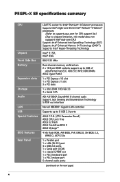
P5GPL-X SE specifications summary CPU Chipset Front Side Bus Memory Expansion slots Storage A u d i o L A N USB Special features BIOS features Rear Panel LGA775 socket for Intel® Pentium® 4/Celeron® processors Supports Intel® single-core 65nm Intel® Pentium® 4/Celeron® processors (Refer to support.asus.com for CPU support list) (Due to chipset limitation, this...
P5GPL-X SE specifications summary CPU Chipset Front Side Bus Memory Expansion slots Storage A u d i o L A N USB Special features BIOS features Rear Panel LGA775 socket for Intel® Pentium® 4/Celeron® processors Supports Intel® single-core 65nm Intel® Pentium® 4/Celeron® processors (Refer to support.asus.com for CPU support list) (Due to chipset limitation, this...

Motherboard Installation Guide
Page 11
...P5GPL-X SE specifications summary O v e r c l o c k i n g Internal c o n n e c t o r s Hardware monitoring Power Requirement Form Factor M a n a g e a b i l i t y Support CD c o n t e n t s ASUS CPU Lock Free Technology ASUS AI Overclocking (Intelligent CPU frequency tuner) CPU and Memory voltage adjustable SFS (Stepless Frequency Selection) from 100MHz up to change without notice. ASUS...WfM2.0, PXE, WOL by PME, WOR by PME, Chassis Intrusion Device drivers ASUS PC Probe ASUS Live Update utility Anti-virus utility (OEM version) *Specifications are subject to ...
...P5GPL-X SE specifications summary O v e r c l o c k i n g Internal c o n n e c t o r s Hardware monitoring Power Requirement Form Factor M a n a g e a b i l i t y Support CD c o n t e n t s ASUS CPU Lock Free Technology ASUS AI Overclocking (Intelligent CPU frequency tuner) CPU and Memory voltage adjustable SFS (Stepless Frequency Selection) from 100MHz up to change without notice. ASUS...WfM2.0, PXE, WOL by PME, WOR by PME, Chassis Intrusion Device drivers ASUS PC Probe ASUS Live Update utility Anti-virus utility (OEM version) *Specifications are subject to ...

Motherboard Installation Guide
Page 13
This chapter describes the motherboard features and the new technologies it supports. 1Product introduction ASUS P5GPL-X SE 1-13
This chapter describes the motherboard features and the new technologies it supports. 1Product introduction ASUS P5GPL-X SE 1-13
Motherboard Installation Guide
Page 14
.... 1-14 Chapter 1: Product introduction Before you for the following items. Motherboard ASUS P5GPL-X SE motherboard Cables 1 x Serial ATA signal cables 1 x Serial ATA power cables 1 x Ultra DMA cables 1 x Floppy disk drive cable Accessories I/O shield Application CDs ASUS motherboard support CD Documentation User guide If any of ASUS quality motherboards! 1.1 Welcome! The motherboard delivers a host of new features...
.... 1-14 Chapter 1: Product introduction Before you for the following items. Motherboard ASUS P5GPL-X SE motherboard Cables 1 x Serial ATA signal cables 1 x Serial ATA power cables 1 x Ultra DMA cables 1 x Floppy disk drive cable Accessories I/O shield Application CDs ASUS motherboard support CD Documentation User guide If any of ASUS quality motherboards! 1.1 Welcome! The motherboard delivers a host of new features...
Motherboard Installation Guide
Page 15
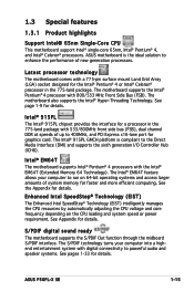
... side bus (FSB), dual channel DDR at speeds of up to run on the CPU loading and system speed or power requirement. ASUS P5GPL-X SE 1-15 Intel® 915PL The Intel® 915PL chipset provides the interface for details. Enhanced Intel SpeedStep® Technology (EIST) ...PDIF interface. The Intel® 915PL GMCH platform is the ideal solution to the Direct Media Interface (DMI) and supports the sixth generation I/O Controller Hub (ICH6). The motherboard supports the Intel® Pentium® 4 processor with the Intel® EM64T (Extended Memory 64 Technology). See page 1-9...
... side bus (FSB), dual channel DDR at speeds of up to run on the CPU loading and system speed or power requirement. ASUS P5GPL-X SE 1-15 Intel® 915PL The Intel® 915PL chipset provides the interface for details. Enhanced Intel SpeedStep® Technology (EIST) ...PDIF interface. The Intel® 915PL GMCH platform is the ideal solution to the Direct Media Interface (DMI) and supports the sixth generation I/O Controller Hub (ICH6). The motherboard supports the Intel® Pentium® 4 processor with the Intel® EM64T (Extended Memory 64 Technology). See page 1-9...
Motherboard Installation Guide
Page 16
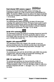
...and Internet applications. See pages 1-24, 1-27, 1-30 and 2-21 for details. Dual-channel DDR memory support Employing the Double Data Rate (DDR) memory technology, the motherboard supports up to meet your Internet, LAN, and file sharing requirements. This high speed interface is backward compatible with ... See page 1-16 for details. 1-16 Chapter 1: Product introduction See page 1-26 for details. Serial ATA technology The motherboard supports the Serial ATA technology through the Serial ATA interfaces and the Intel® ICH6. PCI Express™ interface The motherboard fully...
...and Internet applications. See pages 1-24, 1-27, 1-30 and 2-21 for details. Dual-channel DDR memory support Employing the Double Data Rate (DDR) memory technology, the motherboard supports up to meet your Internet, LAN, and file sharing requirements. This high speed interface is backward compatible with ... See page 1-16 for details. 1-16 Chapter 1: Product introduction See page 1-26 for details. Serial ATA technology The motherboard supports the Serial ATA technology through the Serial ATA interfaces and the Intel® ICH6. PCI Express™ interface The motherboard fully...
Motherboard Installation Guide
Page 17
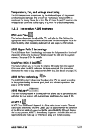
...present in case when the BIOS codes and data are corrupted. ASUS P5GPL-X SE 1-17 Setting the appropriate BIOS setting automatically reduces the CPU multiplier ...failure detection. The system fan rotation per minute (RPM) is monitored for critical components. 1.3.2 Innovative ASUS features CPU Lock Free This feature allows you to personalize and add style to prevent overheating and damage....feature allows you can report shorts and faults up to restore the original BIOS data from the support CD in the motherboard allows you to adjust the CPU multiplier to 14x. This protection eliminates ...
...present in case when the BIOS codes and data are corrupted. ASUS P5GPL-X SE 1-17 Setting the appropriate BIOS setting automatically reduces the CPU multiplier ...failure detection. The system fan rotation per minute (RPM) is monitored for critical components. 1.3.2 Innovative ASUS features CPU Lock Free This feature allows you to personalize and add style to prevent overheating and damage....feature allows you can report shorts and faults up to restore the original BIOS data from the support CD in the motherboard allows you to adjust the CPU multiplier to 14x. This protection eliminates ...

Motherboard Installation Guide
Page 28
... illustrates the location of the recommended configurations in this motherboard. 1-28 Chapter 1: Product introduction Use any of the sockets: P5GPL-X ® P5GPL-X SE 184-pin DDR DIMM sockets 1.7.2 Memory Configurations You may cause memory sizing error or system boot failure. For optimum compatibility,.... DIMM_A1 DIMM_B1 1.7 System memory 1.7.1 Overview The motherboard comes with 128 Mb memory chips or double-sided x16 memory chips are not supported in this section. • Installing DDR DIMMs other than the recommended configurations may install 256 MB, 512 MB and 1 GB unbuffered...
... illustrates the location of the recommended configurations in this motherboard. 1-28 Chapter 1: Product introduction Use any of the sockets: P5GPL-X ® P5GPL-X SE 184-pin DDR DIMM sockets 1.7.2 Memory Configurations You may cause memory sizing error or system boot failure. For optimum compatibility,.... DIMM_A1 DIMM_B1 1.7 System memory 1.7.1 Overview The motherboard comes with 128 Mb memory chips or double-sided x16 memory chips are not supported in this section. • Installing DDR DIMMs other than the recommended configurations may install 256 MB, 512 MB and 1 GB unbuffered...

Motherboard Installation Guide
Page 29
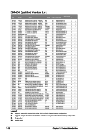
... be the same to ensure optimum performance. [DDR_A1(Channel A)= DDR_B1(Channel B)] DDR400 Qualified Vendors List Size Vendor Model Brand Side(s) Component DIMM support A B 257MB 258MB 256MB 512MB 512MB 1024MB 1024MB 256MB 256MB 256MB 256MB 512MB 512MB 512MB 1024MB 256MB 256MB 512MB 512MB 1024MB 256MB 512MB 512MB 512MB...K4H510838B-TCCC V V58C2256804SAT5B V V K4H560838F-TCCC V V K4H560838F-TCCC V NT5DS64M8BT-5T V V NT5DS32M8CT-5T V V NT5DS32M16BT-5T V V NT5DS64M8BT-5T V V NT5DS3232M8BT-5T V V NT5DS32M8CT-5T V V (Continued on the next page) ASUS P5GPL-X SE 1-17
... be the same to ensure optimum performance. [DDR_A1(Channel A)= DDR_B1(Channel B)] DDR400 Qualified Vendors List Size Vendor Model Brand Side(s) Component DIMM support A B 257MB 258MB 256MB 512MB 512MB 1024MB 1024MB 256MB 256MB 256MB 256MB 512MB 512MB 512MB 1024MB 256MB 256MB 512MB 512MB 1024MB 256MB 512MB 512MB 512MB...K4H510838B-TCCC V V58C2256804SAT5B V V K4H560838F-TCCC V V K4H560838F-TCCC V NT5DS64M8BT-5T V V NT5DS32M8CT-5T V V NT5DS32M16BT-5T V V NT5DS64M8BT-5T V V NT5DS3232M8BT-5T V V NT5DS32M8CT-5T V V (Continued on the next page) ASUS P5GPL-X SE 1-17
Motherboard Installation Guide
Page 30
... pair of Dual-channel memory configuration. DDR400 Qualified Vendors List DIMM support Size Vendor Model Brand Side(s) Component A B 256MB A DATA MDOAD5F3G31Y0D1E02 DDR400 N/A SS ADD8608A8A-5B V V 512MB A DATA MDOAD5F3H41Y0D1E02 DDR400 N/A ...U24512ADWBG6H20 DS V 256MB Winbond W9425GCDB-5 DDR400 Winbond SS W942508CH-5 V V 512MB Winbond W9451GCDB-5 DDR400 Winbond DS W942508CH-5 V V Legend: A - supports one pair of modules inserted into two slots as one module inserted into either slot, in a Single-channel memory configuration. B - Single-sided DS -
... pair of Dual-channel memory configuration. DDR400 Qualified Vendors List DIMM support Size Vendor Model Brand Side(s) Component A B 256MB A DATA MDOAD5F3G31Y0D1E02 DDR400 N/A SS ADD8608A8A-5B V V 512MB A DATA MDOAD5F3H41Y0D1E02 DDR400 N/A ...U24512ADWBG6H20 DS V 256MB Winbond W9425GCDB-5 DDR400 Winbond SS W942508CH-5 V V 512MB Winbond W9451GCDB-5 DDR400 Winbond DS W942508CH-5 V V Legend: A - supports one pair of modules inserted into two slots as one module inserted into either slot, in a Single-channel memory configuration. B - Single-sided DS -

Motherboard Installation Guide
Page 31
... that it flips out with your fingers when pressing the retaining clips. Firmly insert the DIMM into a socket to unlock 1 the DIMM. 1 DDR DIMM notch Support the DIMM lightly with extra force. 2. Remove the DIMM from the socket. Locked Retaining Clip 1.7.4 Removing a DIMM Follow these steps to both the motherboard and... before adding or removing DIMMs or other system components. The DIMM might get damaged when it fits in place and the DIMM is properly seated. ASUS P5GPL-X SE 1-19
... that it flips out with your fingers when pressing the retaining clips. Firmly insert the DIMM into a socket to unlock 1 the DIMM. 1 DDR DIMM notch Support the DIMM lightly with extra force. 2. Remove the DIMM from the socket. Locked Retaining Clip 1.7.4 Removing a DIMM Follow these steps to both the motherboard and... before adding or removing DIMMs or other system components. The DIMM might get damaged when it fits in place and the DIMM is properly seated. ASUS P5GPL-X SE 1-19
Motherboard Installation Guide
Page 32
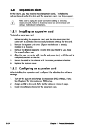
... documentation that came with the slot and press firmly until the card is already installed in a chassis). 3. Remove the bracket opposite the slot that they support. Assign an IRQ to the tables on the system and change the necessary BIOS settings, if any. Align the card connector with it by adjusting...
... documentation that came with the slot and press firmly until the card is already installed in a chassis). 3. Remove the bracket opposite the slot that they support. Assign an IRQ to the tables on the system and change the necessary BIOS settings, if any. Align the card connector with it by adjusting...

Motherboard Installation Guide
Page 33
... IDE Channel * These IRQs are usually available for this motherboard PCI slot 1 PCI slot 2 PCI slot 3 Onboard LAN A B - - - - - ASUS P5GPL-X SE 1-21 used When using PCI cards on shared slots, ensure that the drivers support "Share IRQ" or that the cards do not need IRQ assignments. IRQ assignments for ISA or PCI devices. C D E F G H - - - - Otherwise...
... IDE Channel * These IRQs are usually available for this motherboard PCI slot 1 PCI slot 2 PCI slot 3 Onboard LAN A B - - - - - ASUS P5GPL-X SE 1-21 used When using PCI cards on shared slots, ensure that the drivers support "Share IRQ" or that the cards do not need IRQ assignments. IRQ assignments for ISA or PCI devices. C D E F G H - - - - Otherwise...

Motherboard Installation Guide
Page 34
The figure shows a LAN card installed on a PCI slot. 1.8.5 PCI Express x16 slot This motherboard supports PCI Express x16 graphic cards that comply with the PCI Express specifications. The figure shows a graphics card installed on the PCI Express x1 slot. 1-22 ...Chapter 1: Product introduction The figure shows a network card installed on the PCI Express x16 slot. 1.8.6 PCI Express x1 slot This motherboard supports PCI Express x1 network cards, SCSI cards and other cards that comply with PCI specifications. 1.8.4 PCI slots The PCI slots...
The figure shows a LAN card installed on a PCI slot. 1.8.5 PCI Express x16 slot This motherboard supports PCI Express x16 graphic cards that comply with the PCI Express specifications. The figure shows a graphics card installed on the PCI Express x1 slot. 1-22 ...Chapter 1: Product introduction The figure shows a network card installed on the PCI Express x16 slot. 1.8.6 PCI Express x1 slot This motherboard supports PCI Express x1 network cards, SCSI cards and other cards that comply with PCI specifications. 1.8.4 PCI slots The PCI slots...

Motherboard Installation Guide
Page 40
...fan cables to prevent incorrect cable connection when using an FDD cable with a covered Pin 5. P5GPL-X SE Floppy disk drive connector 3. CPU and chassis fan connectors (4-pin CPU_FAN, 3-pin CHA_FAN) The fan connectors support cooling fans of 350mA~2000mA (24W max.) or a total of 1A~3.48A (41.36W ...on the fan connectors. These are not jumpers! GND +12V Rotation GND CPU FAN PWR CPU FAN IN CPU FAN PWM CHA_FAN P5GPL-X ® CPU_FAN P5GPL-X SE Fan connectors 1-28 Chapter 1: Product introduction 2. DO NOT place jumper caps on the motherboard, making sure that the black wire ...
...fan cables to prevent incorrect cable connection when using an FDD cable with a covered Pin 5. P5GPL-X SE Floppy disk drive connector 3. CPU and chassis fan connectors (4-pin CPU_FAN, 3-pin CHA_FAN) The fan connectors support cooling fans of 350mA~2000mA (24W max.) or a total of 1A~3.48A (41.36W ...on the fan connectors. These are not jumpers! GND +12V Rotation GND CPU FAN PWR CPU FAN IN CPU FAN PWM CHA_FAN P5GPL-X ® CPU_FAN P5GPL-X SE Fan connectors 1-28 Chapter 1: Product introduction 2. DO NOT place jumper caps on the motherboard, making sure that the black wire ...

Motherboard Installation Guide
Page 41
...GND RSATA_TXN4 RSATA_TXP4 GND SATA3 GND RSATA_RXN3 RSATA_RXP3 GND RSATA_TXN3 RSATA_TXP3 GND P5GPL-X ® SATA2 GND RSATA_TXP2 RSATA_TXN2 GND RSATA_RXP2 RSATA_RXN2 GND GND RSATA_TXP1 RSATA_TXN1 GND RSATA_RXP1 RSATA_RXN1 GND SATA1 P5GPL-X SE SATA connectors Important notes on Serial ATA • Install the Windows... table below for Serial ATA hard disk drives. Refer to support S3 function. Serial ATA Master/Slave connectors Connector SATA1, SATA2 SATA3, SATA4 Setting Master Slave Use Boot disk Data disk ASUS P5GPL-X SE 1-29 Serial ATA connectors (7-pin SATA1, SATA2, SATA3, ...
...GND RSATA_TXN4 RSATA_TXP4 GND SATA3 GND RSATA_RXN3 RSATA_RXP3 GND RSATA_TXN3 RSATA_TXP3 GND P5GPL-X ® SATA2 GND RSATA_TXP2 RSATA_TXN2 GND RSATA_RXP2 RSATA_RXN2 GND GND RSATA_TXP1 RSATA_TXN1 GND RSATA_RXP1 RSATA_RXN1 GND SATA1 P5GPL-X SE SATA connectors Important notes on Serial ATA • Install the Windows... table below for Serial ATA hard disk drives. Refer to support S3 function. Serial ATA Master/Slave connectors Connector SATA1, SATA2 SATA3, SATA4 Setting Master Slave Use Boot disk Data disk ASUS P5GPL-X SE 1-29 Serial ATA connectors (7-pin SATA1, SATA2, SATA3, ...

Motherboard Installation Guide
Page 45
...definition Legacy AC'97 compliant definition AGND +5VA BLINE_OUT_R BLINE_OUT_L GND PRESENCE# SENSE1_RETUR SENSE2_RETUR P5GPL-X ® MIC2 MICPWR Line out_R NC Line out_L PORT1 L PORT1 R PORT2 R SENSE_SEND PORT2 L P5GPL-X SE Analog front panel connector Connect a high-definiton front panel audio module to this ...The S/PDIF module is purchased separately. Connect one end of the front panel audio I /O module that supports either HD Audio or legacy AC '97 audio standard. ASUS P5GPL-X SE 1-33 Connect one end of the motherboard. 10. Front panel audio connector (10-1 pin AAFP) This...
...definition Legacy AC'97 compliant definition AGND +5VA BLINE_OUT_R BLINE_OUT_L GND PRESENCE# SENSE1_RETUR SENSE2_RETUR P5GPL-X ® MIC2 MICPWR Line out_R NC Line out_L PORT1 L PORT1 R PORT2 R SENSE_SEND PORT2 L P5GPL-X SE Analog front panel connector Connect a high-definiton front panel audio module to this ...The S/PDIF module is purchased separately. Connect one end of the front panel audio I /O module that supports either HD Audio or legacy AC '97 audio standard. ASUS P5GPL-X SE 1-33 Connect one end of the motherboard. 10. Front panel audio connector (10-1 pin AAFP) This...


