
Motherboard Installation Guide
Page 1
P5GPL-X SE Motherboard
P5GPL-X SE Motherboard

Motherboard Installation Guide
Page 3
Contents Notices vi Safety information vii About this guide viii Typography ix P5GPL-X SE specifications summary x Chapter 1: Product introduction 1.1 Welcome 1-2 1.2 Package contents 1-2 1.3 Special features 1-3 1.3.1 Product highlights 1-3 1.3.2 Innovative ASUS features 1-5 1.4 Before you proceed 1-6 1.5 Motherboard overview 1-7 1.5.1 Placement direction 1-7 1.5.2 Screw holes 1-7 1.5.3 Motherboard layout 1-8 1.6 Central Processing Unit (CPU 1-9 1.6.1 Installling the CPU 1-9 1.6.2 Installling the CPU heatsink and fan 1-12 1.6.3 Uninstalling the...
Contents Notices vi Safety information vii About this guide viii Typography ix P5GPL-X SE specifications summary x Chapter 1: Product introduction 1.1 Welcome 1-2 1.2 Package contents 1-2 1.3 Special features 1-3 1.3.1 Product highlights 1-3 1.3.2 Innovative ASUS features 1-5 1.4 Before you proceed 1-6 1.5 Motherboard overview 1-7 1.5.1 Placement direction 1-7 1.5.2 Screw holes 1-7 1.5.3 Motherboard layout 1-8 1.6 Central Processing Unit (CPU 1-9 1.6.1 Installling the CPU 1-9 1.6.2 Installling the CPU heatsink and fan 1-12 1.6.3 Uninstalling the...

Motherboard Installation Guide
Page 7
... from connectors, slots, sockets and circuitry. • Avoid dust, humidity, and temperature extremes. vii Operation safety • Before installing the motherboard and adding devices on a stable surface. • If you are not sure about the voltage of electronic products. Do not place the product...signal cables are unplugged. • Seek professional assistance before you add a device. • Before connecting or removing signal cables from the motherboard, ensure that all power cables are connected. If you detect any area where it may become wet. • Place the product on...
... from connectors, slots, sockets and circuitry. • Avoid dust, humidity, and temperature extremes. vii Operation safety • Before installing the motherboard and adding devices on a stable surface. • If you are not sure about the voltage of electronic products. Do not place the product...signal cables are unplugged. • Seek professional assistance before you add a device. • Before connecting or removing signal cables from the motherboard, ensure that all power cables are connected. If you detect any area where it may become wet. • Place the product on...

Motherboard Installation Guide
Page 8
... package. How this guide This user guide contains the information you have been added by your dealer. ASUS websites The ASUS website provides updated information on the motherboard. • Chapter 2: BIOS setup This chapter tells how to perform when installing system components. Where ...to find more information Refer to the ASUS contact information. 2. viii It includes description of the motherboard and the new technology it supports. About this guide is organized This manual contains the following sources ...
... package. How this guide This user guide contains the information you have been added by your dealer. ASUS websites The ASUS website provides updated information on the motherboard. • Chapter 2: BIOS setup This chapter tells how to perform when installing system components. Where ...to find more information Refer to the ASUS contact information. 2. viii It includes description of the motherboard and the new technology it supports. About this guide is organized This manual contains the following sources ...

Motherboard Installation Guide
Page 13
This chapter describes the motherboard features and the new technologies it supports. 1Product introduction ASUS P5GPL-X SE 1-13
This chapter describes the motherboard features and the new technologies it supports. 1Product introduction ASUS P5GPL-X SE 1-13
Motherboard Installation Guide
Page 14
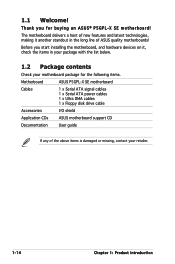
... in the long line of the above items is damaged or missing, contact your retailer. 1-14 Chapter 1: Product introduction Before you for the following items. Motherboard ASUS P5GPL-X SE motherboard Cables 1 x Serial ATA signal cables 1 x Serial ATA power cables 1 x Ultra DMA cables 1 x Floppy disk drive cable Accessories I/O shield Application CDs...
... in the long line of the above items is damaged or missing, contact your retailer. 1-14 Chapter 1: Product introduction Before you for the following items. Motherboard ASUS P5GPL-X SE motherboard Cables 1 x Serial ATA signal cables 1 x Serial ATA power cables 1 x Ultra DMA cables 1 x Floppy disk drive cable Accessories I/O shield Application CDs...
Motherboard Installation Guide
Page 15
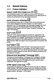
...run on the CPU loading and system speed or power requirement. ASUS P5GPL-X SE 1-15 Latest processor technology The motherboard comes with a 775-pin surface mount Land Grid Array (LGA) socket designed for details. The motherboard supports the Intel® Pentium® 4 processor with the Intel... Express x16-lane port for faster and more efficient computing. Intel® EM64T The motherboard supports Intel® Pentium® 4 processors with 800/533 MHz Front Side Bus (FSB). ASUS motherboard is compliant to powerful audio and speaker systems. See pages 1-33 for details. ...
...run on the CPU loading and system speed or power requirement. ASUS P5GPL-X SE 1-15 Latest processor technology The motherboard comes with a 775-pin surface mount Land Grid Array (LGA) socket designed for details. The motherboard supports the Intel® Pentium® 4 processor with the Intel... Express x16-lane port for faster and more efficient computing. Intel® EM64T The motherboard supports Intel® Pentium® 4 processors with 800/533 MHz Front Side Bus (FSB). ASUS motherboard is compliant to powerful audio and speaker systems. See pages 1-33 for details. ...
Motherboard Installation Guide
Page 16
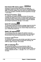
... to ‑point serial interconnections between devices and allows higher clockspeeds by carrying data in packets. Serial ATA technology The motherboard supports the Serial ATA technology through the Serial ATA interfaces and the Intel® ICH6. Dual-channel DDR memory support Employing the... DDR400/333 DIMMs. The ultra-fast 400MHz memory bus delivers the required bandwidth for your growing networking needs. Gigabit LAN support This motherboard comes with lower pin count, reduced voltage requirement, and up to meet your Internet, LAN, and file sharing requirements. See page...
... to ‑point serial interconnections between devices and allows higher clockspeeds by carrying data in packets. Serial ATA technology The motherboard supports the Serial ATA technology through the Serial ATA interfaces and the Intel® ICH6. Dual-channel DDR memory support Employing the... DDR400/333 DIMMs. The ultra-fast 400MHz memory bus delivers the required bandwidth for your growing networking needs. Gigabit LAN support This motherboard comes with lower pin count, reduced voltage requirement, and up to meet your Internet, LAN, and file sharing requirements. See page...
Motherboard Installation Guide
Page 17
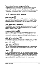
...the CPU multiplier value for details. ASUS P5GPL-X SE 1-17 With this utility, you can report shorts and faults up to prevent overheating and damage. CrashFree BIOS 2 This feature allows you to restore the original BIOS data from the support CD in the motherboard allows you to adjust the CPU... multiplier to your system with customizable boot logos. ASUS MyLogo™ This new feature present in case when the BIOS codes and data are corrupted....
...the CPU multiplier value for details. ASUS P5GPL-X SE 1-17 With this utility, you can report shorts and faults up to prevent overheating and damage. CrashFree BIOS 2 This feature allows you to restore the original BIOS data from the support CD in the motherboard allows you to adjust the CPU... multiplier to your system with customizable boot logos. ASUS MyLogo™ This new feature present in case when the BIOS codes and data are corrupted....

Motherboard Installation Guide
Page 18
P5GPL-X ® SB_PWR ON P5GPL-X SE Onboard LED Standby Power OFF Powered Off 1-18 Chapter 1: Product introduction This is a reminder that you should shut down the system and unplug the power ... wrist strap or touch a safely grounded object or to a metal object, such as the power supply case, before removing or plugging in any motherboard component. Onboard LED The motherboard comes with the component. • Before you install or remove any component, ensure that the system is ON, in sleep mode, or in...
P5GPL-X ® SB_PWR ON P5GPL-X SE Onboard LED Standby Power OFF Powered Off 1-18 Chapter 1: Product introduction This is a reminder that you should shut down the system and unplug the power ... wrist strap or touch a safely grounded object or to a metal object, such as the power supply case, before removing or plugging in any motherboard component. Onboard LED The motherboard comes with the component. • Before you install or remove any component, ensure that the system is ON, in sleep mode, or in...

Motherboard Installation Guide
Page 19
The edge with external ports goes to the rear part of the chassis P5GPL-X SE ® ASUS P5GPL-X SE 1-19 Do not overtighten the screws! Place this side towards the rear of the chassis as indicated in the correct orientation. 1.5 Motherboard overview Before you install the motherboard, study the configuration of your chassis to ensure that you physical...
The edge with external ports goes to the rear part of the chassis P5GPL-X SE ® ASUS P5GPL-X SE 1-19 Do not overtighten the screws! Place this side towards the rear of the chassis as indicated in the correct orientation. 1.5 Motherboard overview Before you install the motherboard, study the configuration of your chassis to ensure that you physical...

Motherboard Installation Guide
Page 20
... module) EATXPWR PRI_IDE 30.5cm (12.0in) 1.5.3 Motherboard layout 18.2cm (7.2in) PS/2KBMS T: Mouse B: Keyboard KBPWR SPDIF_O ATX12V LGA775 PARALLEL PORT COM1 F_USB12 LAN_USB34 Top:Line In Center:Line Out Below:Mic In USBPW1 Intel® 915PL CHA_FAN CPU_FAN Super I/O Marvell 88E8001 P5GPL-X SE PCIEX16 ® PCI1 PCI2 Intel® ICH6 Intel...
... module) EATXPWR PRI_IDE 30.5cm (12.0in) 1.5.3 Motherboard layout 18.2cm (7.2in) PS/2KBMS T: Mouse B: Keyboard KBPWR SPDIF_O ATX12V LGA775 PARALLEL PORT COM1 F_USB12 LAN_USB34 Top:Line In Center:Line Out Below:Mic In USBPW1 Intel® 915PL CHA_FAN CPU_FAN Super I/O Marvell 88E8001 P5GPL-X SE PCIEX16 ® PCI1 PCI2 Intel® ICH6 Intel...

Motherboard Installation Guide
Page 21
ASUS will shoulder the cost of the motherboard, make sure that the PnP cap is shipment/ transit-related. • Keep the cap after installing the motherboard. P5GPL-X ® P5GPL-X SE CPU Socket 775 Before installing the CPU, make sure that the socket box is facing towards you and... pins are not bent. ASUS P5GPL-X SE 1-21 Contact your retailer immediately if the PnP cap is on the LGA775 socket. • The product warranty does not cover damage to the PnP cap/socket pins/motherboard components. 1.6 Central Processing Unit (CPU) The motherboard comes with a surface mount...
ASUS will shoulder the cost of the motherboard, make sure that the PnP cap is shipment/ transit-related. • Keep the cap after installing the motherboard. P5GPL-X ® P5GPL-X SE CPU Socket 775 Before installing the CPU, make sure that the socket box is facing towards you and... pins are not bent. ASUS P5GPL-X SE 1-21 Contact your retailer immediately if the PnP cap is on the LGA775 socket. • The product warranty does not cover damage to the PnP cap/socket pins/motherboard components. 1.6 Central Processing Unit (CPU) The motherboard comes with a surface mount...
Motherboard Installation Guide
Page 24
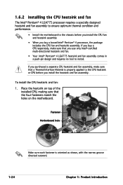
If you purchased a separate CPU heatsink and fan assembly, make sure that the four fasteners match the holes on the motherboard. To install the CPU heatsink and fan: 1. 1.6.2 Installling the CPU heatsink and fan The Intel® Pentium® 4 LGA775 processor requires... a specially designed heatsink and fan assembly to ensure optimum thermal condition and performance. • Install the motherboard to the chassis before you install the heatsink and fan assembly. If you buy a CPU separately, make sure that a Thermal Interface Material is...
If you purchased a separate CPU heatsink and fan assembly, make sure that the four fasteners match the holes on the motherboard. To install the CPU heatsink and fan: 1. 1.6.2 Installling the CPU heatsink and fan The Intel® Pentium® 4 LGA775 processor requires... a specially designed heatsink and fan assembly to ensure optimum thermal condition and performance. • Install the motherboard to the chassis before you install the heatsink and fan assembly. If you buy a CPU separately, make sure that a Thermal Interface Material is...

Motherboard Installation Guide
Page 25
When the fan and heatsink assembly is in place. Push down two fasteners at a time in a diagonal sequence to secure the heatsink and fan B assembly in place, connect the CPU fan cable to the connector on the motherboard labeled CPU_FAN. ASUS P5GPL-X SE 1-25 GND CPU FAN PWR CPU FAN IN CPU FAN PWM P5GPL-X ® CPU_FAN P5GPL-X SE CPU fan connector Do not forget to plug this connector. Hardware monitoring errors can occur if you fail to connect the CPU fan connector! 2. A A A B B B A 3.
When the fan and heatsink assembly is in place. Push down two fasteners at a time in a diagonal sequence to secure the heatsink and fan B assembly in place, connect the CPU fan cable to the connector on the motherboard labeled CPU_FAN. ASUS P5GPL-X SE 1-25 GND CPU FAN PWR CPU FAN IN CPU FAN PWM P5GPL-X ® CPU_FAN P5GPL-X SE CPU fan connector Do not forget to plug this connector. Hardware monitoring errors can occur if you fail to connect the CPU fan connector! 2. A A A B B B A 3.

Motherboard Installation Guide
Page 26
B A B B A 1-26 Chapter 1: Product introduction Disconnect the CPU fan cable from the A A motherboard. 1.6.3 Uninstalling the CPU heatsink and fan To uninstall the CPU heatsink and fan: 1. Rotate each fastener counterclockwise. 3. Pull up two fasteners at a time in a diagonal sequence to disengage the heatsink B and fan assembly from the connector on the motherboard. 2.
B A B B A 1-26 Chapter 1: Product introduction Disconnect the CPU fan cable from the A A motherboard. 1.6.3 Uninstalling the CPU heatsink and fan To uninstall the CPU heatsink and fan: 1. Rotate each fastener counterclockwise. 3. Pull up two fasteners at a time in a diagonal sequence to disengage the heatsink B and fan assembly from the connector on the motherboard. 2.

Motherboard Installation Guide
Page 27
ASUS P5GPL-X SE 1-27 Rotate each fastener should be oriented as shown, with the narrow groove directed outward. When reset, each fastener clockwise to reset the orientation. Remove the heatsink and fan assembly from the motherboard. 5. 4.
ASUS P5GPL-X SE 1-27 Rotate each fastener should be oriented as shown, with the narrow groove directed outward. When reset, each fastener clockwise to reset the orientation. Remove the heatsink and fan assembly from the motherboard. 5. 4.

Motherboard Installation Guide
Page 28
DIMM_A1 DIMM_B1 1.7 System memory 1.7.1 Overview The motherboard comes with 128 Mb memory chips or double-sided x16 memory chips are not supported in this section. • Installing DDR DIMMs other than the ...-pin Double Data Rate (DDR) Dual Inline Memory Modules (DIMM) sockets. The following figure illustrates the location of the recommended configurations in this motherboard. 1-28 Chapter 1: Product introduction Use any of the sockets: P5GPL-X ® P5GPL-X SE 184-pin DDR DIMM sockets 1.7.2 Memory Configurations You may cause memory sizing error or system boot failure.
DIMM_A1 DIMM_B1 1.7 System memory 1.7.1 Overview The motherboard comes with 128 Mb memory chips or double-sided x16 memory chips are not supported in this section. • Installing DDR DIMMs other than the ...-pin Double Data Rate (DDR) Dual Inline Memory Modules (DIMM) sockets. The following figure illustrates the location of the recommended configurations in this motherboard. 1-28 Chapter 1: Product introduction Use any of the sockets: P5GPL-X ® P5GPL-X SE 184-pin DDR DIMM sockets 1.7.2 Memory Configurations You may cause memory sizing error or system boot failure.

Motherboard Installation Guide
Page 31
... DIMM is properly seated. Remove the DIMM from the socket. 1.7.3 Installing a DIMM Make sure to both the motherboard and the components. 1. Align a DIMM on the socket such that it flips out with extra force. 2. ASUS P5GPL-X SE 1-19 Failure to do so may cause severe damage to unplug the power supply before adding or...
... DIMM is properly seated. Remove the DIMM from the socket. 1.7.3 Installing a DIMM Make sure to both the motherboard and the components. 1. Align a DIMM on the socket such that it flips out with extra force. 2. ASUS P5GPL-X SE 1-19 Failure to do so may cause severe damage to unplug the power supply before adding or...
Motherboard Installation Guide
Page 32
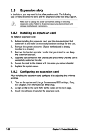
.... 2. Refer to the card. 1.8 Expansion slots In the future, you may need to do so may cause you physical injury and damage motherboard components. 1.8.1 Installing an expansion card To install an expansion card: 1. Failure to install expansion cards. Install the software drivers for the card....press firmly until the card is already installed in a chassis). 3. Turn on the slot. 5. Remove the system unit cover (if your motherboard is completely seated on the system and change the necessary BIOS settings, if any. Replace the system cover. 1.8.2 Configuring an expansion card After...
.... 2. Refer to the card. 1.8 Expansion slots In the future, you may need to do so may cause you physical injury and damage motherboard components. 1.8.1 Installing an expansion card To install an expansion card: 1. Failure to install expansion cards. Install the software drivers for the card....press firmly until the card is already installed in a chassis). 3. Turn on the slot. 5. Remove the system unit cover (if your motherboard is completely seated on the system and change the necessary BIOS settings, if any. Replace the system cover. 1.8.2 Configuring an expansion card After...


