User Manual
Page 4
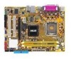
Contents 1.10 Connectors 1-25 1.10.1 Rear panel connectors 1-25 1.10.2 Internal connectors 1-26 Chapter 2: BIOS setup 2.1 Managing and updating your BIOS 2-2 2.1.1 Creating a bootable floppy disk 2-2 2.1.2 ASUS EZ Flash utility 2-3 2.1.3 AFUDOS utility 2-4 2.1.4 ASUS CrashFree BIOS 2 utility 2-6 2.1.5 ASUS Update utility 2-8 2.2 BIOS setup program 2-11 2.2.1 BIOS menu screen 2-12 2.2.2 Menu bar 2-12 2.2.3 Navigation keys 2-12 2.2.4 Menu items 2-13...
Contents 1.10 Connectors 1-25 1.10.1 Rear panel connectors 1-25 1.10.2 Internal connectors 1-26 Chapter 2: BIOS setup 2.1 Managing and updating your BIOS 2-2 2.1.1 Creating a bootable floppy disk 2-2 2.1.2 ASUS EZ Flash utility 2-3 2.1.3 AFUDOS utility 2-4 2.1.4 ASUS CrashFree BIOS 2 utility 2-6 2.1.5 ASUS Update utility 2-8 2.2 BIOS setup program 2-11 2.2.1 BIOS menu screen 2-12 2.2.2 Menu bar 2-12 2.2.3 Navigation keys 2-12 2.2.4 Menu items 2-13...
User Manual
Page 10
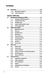
P5GC-MX/1333 specifications summary CPU Chipset Front Side Bus Memory VGA Expansion slots Storage Audio LAN USB Rear panel BIOS features LGA775 socket for Intel® Core™2 Duo / Pentium® D / Pentium® 4 / Celeron® D Processors Compatible with ...), Enhanced Intel SpeedStep® Technology (EIST), and Intel® Hyper-Threading Technology * Refer to www.asus.com for Intel CPU support list Northbridge: Intel® 945GC Southbridge: Intel® ICH7 1333(O.C)*/1066/800 MHz (* when O.C and CPU support 1333MHz FSB) Dual-channel memory architecture 2 x 240-pin...
P5GC-MX/1333 specifications summary CPU Chipset Front Side Bus Memory VGA Expansion slots Storage Audio LAN USB Rear panel BIOS features LGA775 socket for Intel® Core™2 Duo / Pentium® D / Pentium® 4 / Celeron® D Processors Compatible with ...), Enhanced Intel SpeedStep® Technology (EIST), and Intel® Hyper-Threading Technology * Refer to www.asus.com for Intel CPU support list Northbridge: Intel® 945GC Southbridge: Intel® ICH7 1333(O.C)*/1066/800 MHz (* when O.C and CPU support 1333MHz FSB) Dual-channel memory architecture 2 x 240-pin...
User Manual
Page 11
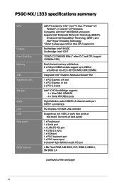
... P5GC-MX/1333 specifications summary Special features Manageability Internal connectors Power Requirement ASUS EZ Flash ASUS CrashFree BIOS 2 ASUS MyLogo™ ASUS Q-Fan WfM 2.0, DMI 2.0, WOL by PME, WOR by PME 2 x USB 2.0 connectors for 4 additional USB 2.0 ports 1 x Floppy disk drive connector 1 x IDE connector for two devices 4 x Serial ATA connectors 1 x CPU fan connector 1 x Chassis fan connector 1 x 24-pin ATX...
... P5GC-MX/1333 specifications summary Special features Manageability Internal connectors Power Requirement ASUS EZ Flash ASUS CrashFree BIOS 2 ASUS MyLogo™ ASUS Q-Fan WfM 2.0, DMI 2.0, WOL by PME, WOR by PME 2 x USB 2.0 connectors for 4 additional USB 2.0 ports 1 x Floppy disk drive connector 1 x IDE connector for two devices 4 x Serial ATA connectors 1 x CPU fan connector 1 x Chassis fan connector 1 x 24-pin ATX...
User Manual
Page 37
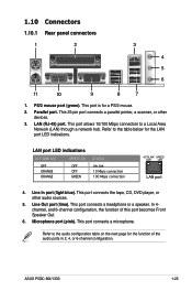
..., or other audio sources. 5. LAN (RJ-45) port. This port connects a headphone or a speaker. This port is for the LAN port LED indications. ASUS P5GC-MX/1333 1-25 1.10 Connectors 1.10.1 Rear panel connectors 1 2 3 4 5 6 11 10 9 8 7 1. PS/2 mouse port (green). This port allows 10/100 Mbps connection to the audio configuration table on the next...
..., or other audio sources. 5. LAN (RJ-45) port. This port connects a headphone or a speaker. This port is for the LAN port LED indications. ASUS P5GC-MX/1333 1-25 1.10 Connectors 1.10.1 Rear panel connectors 1 2 3 4 5 6 11 10 9 8 7 1. PS/2 mouse port (green). This port allows 10/100 Mbps connection to the audio configuration table on the next...
User Manual
Page 44
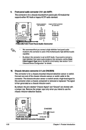
... pin definition pin definition AGND PRESENSE# MIC2_JD HP_HD AGND NC NC NC P5GC-MX/1333 R AAFP MIC2_L MIC2_R Line out_R NC Line out_L MIC2_L MIC2_R HP_R Jack_Sense HP_L P5GC-MX/1333 Front Panel Audio Connector • We recommend that supports either HD Audio or legacy... P5GC-MX/1333 R CHASSIS GND Chassis Signal (Default) +5VSB_MB P5GC-MX/1333 Intrusion Connector 1-32 Chapter 1: Product introduction Remove the jumper caps only when you want to connect a High Definition front panel audio module to this connector is for details. 10. Connect one end of the motherboard's ...
... pin definition pin definition AGND PRESENSE# MIC2_JD HP_HD AGND NC NC NC P5GC-MX/1333 R AAFP MIC2_L MIC2_R Line out_R NC Line out_L MIC2_L MIC2_R HP_R Jack_Sense HP_L P5GC-MX/1333 Front Panel Audio Connector • We recommend that supports either HD Audio or legacy... P5GC-MX/1333 R CHASSIS GND Chassis Signal (Default) +5VSB_MB P5GC-MX/1333 Intrusion Connector 1-32 Chapter 1: Product introduction Remove the jumper caps only when you want to connect a High Definition front panel audio module to this connector is for details. 10. Connect one end of the motherboard's ...
User Manual
Page 45
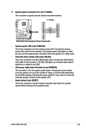
...data is read from or written to this connector. Connect the HDD Activity LED cable to the HDD. • ATX power button/soft-off button (2-pin PWRBTN) This connector is for system reboot without turning off mode depending on the... system power, and blinks when the system is in sleep or soft-off the system power. System panel connector (10-1 pin F_PANEL) This connector supports several chassis-mounted functions. Pressing the power button turns the system ... power button. 11. The IDE LED lights up when you turn on the BIOS settings. ASUS P5GC-MX/1333 1-33
...data is read from or written to this connector. Connect the HDD Activity LED cable to the HDD. • ATX power button/soft-off button (2-pin PWRBTN) This connector is for system reboot without turning off mode depending on the... system power, and blinks when the system is in sleep or soft-off the system power. System panel connector (10-1 pin F_PANEL) This connector supports several chassis-mounted functions. Pressing the power button turns the system ... power button. 11. The IDE LED lights up when you turn on the BIOS settings. ASUS P5GC-MX/1333 1-33
User Manual
Page 70
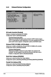
...IRQ4] Allows you to select the Serial Port1 base address. 2.4.5 Onboard Devices Configuration Configure Win627DHG Super IO Chipset HD Audio Controller [Enabled] Front Panel Support Type [HD Audio] Onboard PCIEX 10/100Mb LAN [Enabled] LAN Option ROM [Disabled] Serial Port1 Address [3F8/IRQ4] Parallel Port Address ...10/100Mb LAN [Enabled] Allows you to set to select the Parallel Port base addresses. Configuration options: [Enabled] [Disabled] Front Panel Support Type [AC97] Allows you to legacy AC'97 or high-definition audio depending on the audio standard that the front...
...IRQ4] Allows you to select the Serial Port1 base address. 2.4.5 Onboard Devices Configuration Configure Win627DHG Super IO Chipset HD Audio Controller [Enabled] Front Panel Support Type [HD Audio] Onboard PCIEX 10/100Mb LAN [Enabled] LAN Option ROM [Disabled] Serial Port1 Address [3F8/IRQ4] Parallel Port Address ...10/100Mb LAN [Enabled] Allows you to set to select the Parallel Port base addresses. Configuration options: [Enabled] [Disabled] Front Panel Support Type [AC97] Allows you to legacy AC'97 or high-definition audio depending on the audio standard that the front...


