User Manual
Page 3
Contents Notices...v Safety information vi About this guide vi P5G41T-M LX2 Series specifications summary viii Chapter 1: Product introduction 1.1 Before you proceed 1-1 1.2 Motherboard overview 1-2 1.2.1 Motherboard layout 1-2 1.2.2 Layout contents 1-3 1.3 Central Processing ...operating system 1-16 1.8.2 Support DVD information 1-16 Chapter 2: BIOS information 2.1 Managing and updating your BIOS 2-1 2.1.1 ASUS Update utility 2-1 2.1.2 ASUS EZ Flash 2 2-2 2.1.3 ASUS CrashFree BIOS 2-3 2.2 BIOS setup program 2-3 2.3 Main menu 2-4 2.3.1 System Time 2-4 2.3.2 System Date 2-4 iii
Contents Notices...v Safety information vi About this guide vi P5G41T-M LX2 Series specifications summary viii Chapter 1: Product introduction 1.1 Before you proceed 1-1 1.2 Motherboard overview 1-2 1.2.1 Motherboard layout 1-2 1.2.2 Layout contents 1-3 1.3 Central Processing ...operating system 1-16 1.8.2 Support DVD information 1-16 Chapter 2: BIOS information 2.1 Managing and updating your BIOS 2-1 2.1.1 ASUS Update utility 2-1 2.1.2 ASUS EZ Flash 2 2-2 2.1.3 ASUS CrashFree BIOS 2-3 2.2 BIOS setup program 2-3 2.3 Main menu 2-4 2.3.1 System Time 2-4 2.3.2 System Date 2-4 iii
User Manual
Page 8
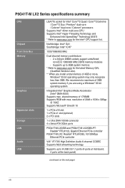
.../LPT: Realtek® RTL8112L Gigabit Ethernet PCIe controller P5G41T-M LX2: Realtek® RTL8103EL 10/100Mbps Ethernet PCIe controller VIA® VT1705 High Definition Audio 6-channel CODEC Supports Multi-streaming technology Supports up to 8GB system memory * Refer to www.asus.com for the Intel® CPU support list. Northbridge: Intel® G41 Southbridge...
.../LPT: Realtek® RTL8112L Gigabit Ethernet PCIe controller P5G41T-M LX2: Realtek® RTL8103EL 10/100Mbps Ethernet PCIe controller VIA® VT1705 High Definition Audio 6-channel CODEC Supports Multi-streaming technology Supports up to 8GB system memory * Refer to www.asus.com for the Intel® CPU support list. Northbridge: Intel® G41 Southbridge...
User Manual
Page 9
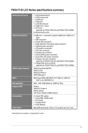
... fan connector 1 x 24-pin EATX power connector 1 x 4-pin ATX 12V power connector 1 x Chassis intrusion connector (optional for P5G41T-M LX2 and P5G41T-M LX2/GB) 1 x Floppy disk drive connector (optional for P5G41T-M LX2 and P5G41T-M LX2/GB) ASUS CrashFree BIOS 3 ASUS Q-Fan ASUS EZ Flash 2 ASUS MyLogo 2 8Mb Flash ROM, AMI BIOS, PnP, DMI 2.0, WfM 2.0, ACPI 2.0a, SM BIOS 2.5 WOL, PXE, PME Wake up...
... fan connector 1 x 24-pin EATX power connector 1 x 4-pin ATX 12V power connector 1 x Chassis intrusion connector (optional for P5G41T-M LX2 and P5G41T-M LX2/GB) 1 x Floppy disk drive connector (optional for P5G41T-M LX2 and P5G41T-M LX2/GB) ASUS CrashFree BIOS 3 ASUS Q-Fan ASUS EZ Flash 2 ASUS MyLogo 2 8Mb Flash ROM, AMI BIOS, PnP, DMI 2.0, WfM 2.0, ACPI 2.0a, SM BIOS 2.5 WOL, PXE, PME Wake up...
User Manual
Page 10
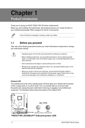
... the power cord is damaged or missing, contact your motherboard package. Failure to do so may cause severe damage to page ix for buying an ASUS® P5G41T-M LX2 Series motherboard! Before you start installing the motherboard, and hardware devices on a grounded antistatic pad or in the bag that came with a standby ... the system and unplug the power cable before removing or plugging in your retailer. 1.1 Before you proceed Take note of the onboard LED. SB_PWR P5G41T-M LX2/GB/LPT ON OFF Standby Power Powered Off P5G41T-M LX2/GB/LPT Onboard power LED 1-1 ASUS P5G41T-M LX2 Series
... the power cord is damaged or missing, contact your motherboard package. Failure to do so may cause severe damage to page ix for buying an ASUS® P5G41T-M LX2 Series motherboard! Before you start installing the motherboard, and hardware devices on a grounded antistatic pad or in the bag that came with a standby ... the system and unplug the power cable before removing or plugging in your retailer. 1.1 Before you proceed Take note of the onboard LED. SB_PWR P5G41T-M LX2/GB/LPT ON OFF Standby Power Powered Off P5G41T-M LX2/GB/LPT Onboard power LED 1-1 ASUS P5G41T-M LX2 Series
User Manual
Page 12
... USB78) 1-11 12. Optical drive audio connector (4-pin CD) 1-12 16. Front panel audio connector (10-1 pin AAFP) 1-11 17. ASUS will shoulder the cost of the motherboard, ensure that the PnP cap is on the LGA775 socket. • The product warranty does not cover ... (RMA) requests only if the motherboard comes with the Intel® Enhanced Intel SpeedStep® Technology (EIST) and Hyper-Threading Technology. 1-3 ASUS P5G41T-M LX2 Series 1.2.2 Layout contents Connectors/Jumpers/Slots/LED 1. IDE connector (40-1 pin PRI_IDE) 8. Contact your retailer immediately if the PnP cap is ...
... USB78) 1-11 12. Optical drive audio connector (4-pin CD) 1-12 16. Front panel audio connector (10-1 pin AAFP) 1-11 17. ASUS will shoulder the cost of the motherboard, ensure that the PnP cap is on the LGA775 socket. • The product warranty does not cover ... (RMA) requests only if the motherboard comes with the Intel® Enhanced Intel SpeedStep® Technology (EIST) and Hyper-Threading Technology. 1-3 ASUS P5G41T-M LX2 Series 1.2.2 Layout contents Connectors/Jumpers/Slots/LED 1. IDE connector (40-1 pin PRI_IDE) 8. Contact your retailer immediately if the PnP cap is ...
User Manual
Page 14
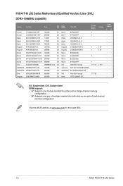
Visit the ASUS website at www.asus.com for the latest QVL. 1-5 ASUS P5G41T-M LX2 Series Timing Dimm (Bios) Voltage Crucial CT12864BA1067.8FF 1024MB SS Crucial CT25664BA1067.16FF 2048MB DS Elpida EBJ51UD8BAFA-AC-E 512MB SS Elpida EBJ51UD8BAFA-AE-E 512MB SS .... • B*: Supports one pair of modules inserted into both slots as one pair of dual-channel memory configuration. Size SS/ Chip DS Brand Chip NO. P5G41T-M LX2 Series Motherboard Qualified Vendors Lists (QVL) DDR3-1066MHz capability Vendor Part No.
Visit the ASUS website at www.asus.com for the latest QVL. 1-5 ASUS P5G41T-M LX2 Series Timing Dimm (Bios) Voltage Crucial CT12864BA1067.8FF 1024MB SS Crucial CT25664BA1067.16FF 2048MB DS Elpida EBJ51UD8BAFA-AC-E 512MB SS Elpida EBJ51UD8BAFA-AE-E 512MB SS .... • B*: Supports one pair of modules inserted into both slots as one pair of dual-channel memory configuration. Size SS/ Chip DS Brand Chip NO. P5G41T-M LX2 Series Motherboard Qualified Vendors Lists (QVL) DDR3-1066MHz capability Vendor Part No.
User Manual
Page 16
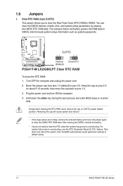
...After clearing the CMOS, reinstall the battery. • You do not help, remove the onboard battery and move the cap back to default values. 1-7 ASUS P5G41T-M LX2 Series 1.6 Jumpers 1. Plug the power cord and turn ON the computer. 4. Removing the cap will cause system boot failure! • If the steps... the CMOS RTC RAM data. Clear RTC RAM (3-pin CLRTC) This jumper allows you to overclocking. CLRTC 12 23 P5G41T-M LX2/GB/LPT Normal (Default) Clear RTC P5G41T-M LX2/GB/LPT Clear RTC RAM To erase the RTC RAM: 1. Except when clearing the RTC RAM, never remove the ...
...After clearing the CMOS, reinstall the battery. • You do not help, remove the onboard battery and move the cap back to default values. 1-7 ASUS P5G41T-M LX2 Series 1.6 Jumpers 1. Plug the power cord and turn ON the computer. 4. Removing the cap will cause system boot failure! • If the steps... the CMOS RTC RAM data. Clear RTC RAM (3-pin CLRTC) This jumper allows you to overclocking. CLRTC 12 23 P5G41T-M LX2/GB/LPT Normal (Default) Clear RTC P5G41T-M LX2/GB/LPT Clear RTC RAM To erase the RTC RAM: 1. Except when clearing the RTC RAM, never remove the ...
User Manual
Page 18
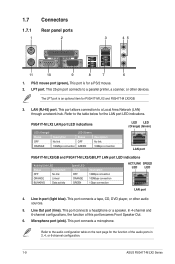
...Green) Status OFF GREEN Description No link 10Mbps connection LED LED (Orange) (Green) LAN port P5G41T-M LX2/GB and P5G41T-M LX2/GB/LPT LAN port LED indications Activity/Link LED Status Description OFF No link ORANGE Linked BLINKING ... Area Network (LAN) through a network hub. In 4-channel and 6-channel configurations, the function of the audio ports in 2, 4, or 6-channel configuration. 1-9 ASUS P5G41T-M LX2 Series This port connects a microphone. LPT port. Microphone port (pink). This port connects a headphone or a speaker. 1.7 1.7.1 1 Connectors Rear panel ports 2...
...Green) Status OFF GREEN Description No link 10Mbps connection LED LED (Orange) (Green) LAN port P5G41T-M LX2/GB and P5G41T-M LX2/GB/LPT LAN port LED indications Activity/Link LED Status Description OFF No link ORANGE Linked BLINKING ... Area Network (LAN) through a network hub. In 4-channel and 6-channel configurations, the function of the audio ports in 2, 4, or 6-channel configuration. 1-9 ASUS P5G41T-M LX2 Series This port connects a microphone. LPT port. Microphone port (pink). This port connects a headphone or a speaker. 1.7 1.7.1 1 Connectors Rear panel ports 2...

User Manual
Page 19
...OK -5 Volts PIN 1 GND +5 Volts GND GND GND GND GND GND P5G41T-M LX2/GB/LPT +5 Volts GND PSON# GND +3 Volts -12 Volts +3 Volts +3 Volts PIN 1 P5G41T-M LX2/GB/LPT ATX power connectors • For a fully configured system, we ...recommend that you use a PSU with a higher power output when configuring a system with ATX 12V Specification 2.0 or later version and provides a minimum power of 400W. • DO NOT forget to the Recommended Power Supply Wattage Calculator at http://support.asus...
...OK -5 Volts PIN 1 GND +5 Volts GND GND GND GND GND GND P5G41T-M LX2/GB/LPT +5 Volts GND PSON# GND +3 Volts -12 Volts +3 Volts +3 Volts PIN 1 P5G41T-M LX2/GB/LPT ATX power connectors • For a fully configured system, we ...recommend that you use a PSU with a higher power output when configuring a system with ATX 12V Specification 2.0 or later version and provides a minimum power of 400W. • DO NOT forget to the Recommended Power Supply Wattage Calculator at http://support.asus...
User Manual
Page 20
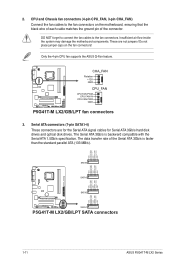
...CPU_FAN CPU FAN PWM CPU FAN IN CPU FAN PWR GND P5G41T-M LX2/GB/LPT fan connectors 3. Serial ATA connectors (7-pin SATA1-4) These connectors are not jumpers! Only the 4-pin CPU fan supports the ASUS Q-Fan feature. DO NOT forget to connect the fan cables ... RSATA_TXP3 GND SATA3 GND RSATA_RXN2 RSATA_RXP2 GND RSATA_TXN2 RSATA_TXP2 GND GND RSATA_RXN1 RSATA_RXP1 GND RSATA_TXN1 RSATA_TXP1 GND P5G41T-M LX2/GB/LPT SATA2 SATA1 P5G41T-M LX2/GB/LPT SATA connectors 1-11 ASUS P5G41T-M LX2 Series CPU and Chassis fan connectors (4-pin CPU_FAN, 3-pin CHA_FAN) Connect the fan cables to the...
...CPU_FAN CPU FAN PWM CPU FAN IN CPU FAN PWR GND P5G41T-M LX2/GB/LPT fan connectors 3. Serial ATA connectors (7-pin SATA1-4) These connectors are not jumpers! Only the 4-pin CPU fan supports the ASUS Q-Fan feature. DO NOT forget to connect the fan cables ... RSATA_TXP3 GND SATA3 GND RSATA_RXN2 RSATA_RXP2 GND RSATA_TXN2 RSATA_TXP2 GND GND RSATA_RXN1 RSATA_RXP1 GND RSATA_TXN1 RSATA_TXP1 GND P5G41T-M LX2/GB/LPT SATA2 SATA1 P5G41T-M LX2/GB/LPT SATA connectors 1-11 ASUS P5G41T-M LX2 Series CPU and Chassis fan connectors (4-pin CPU_FAN, 3-pin CHA_FAN) Connect the fan cables to the...
User Manual
Page 22
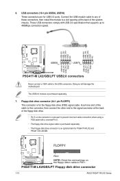
.../LPT USB2.0 connectors Never connect a 1394 cable to PIN 1. P5G41T-M LX2/GB/LPT Floppy disk drive connector 1-13 ASUS P5G41T-M LX2 Series Doing so will damage the motherboard! FLOPPY P5G41T-M LX2/GB/LPT PIN 1 NOTE: Orient the red markings on the connector is an optional item for P5G41T-M LX2 and P5G41T-M LX2/GB. The USB 2.0 module is for USB 2.0 ports. 6. Insert...
.../LPT USB2.0 connectors Never connect a 1394 cable to PIN 1. P5G41T-M LX2/GB/LPT Floppy disk drive connector 1-13 ASUS P5G41T-M LX2 Series Doing so will damage the motherboard! FLOPPY P5G41T-M LX2/GB/LPT PIN 1 NOTE: Orient the red markings on the connector is an optional item for P5G41T-M LX2 and P5G41T-M LX2/GB. The USB 2.0 module is for USB 2.0 ports. 6. Insert...
User Manual
Page 24
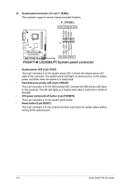
... power LED (2-pin PLED) This 2-pin connector is read from or written to the HDD. • ATX power button/soft-off the system power. 1-15 ASUS P5G41T-M LX2 Series Connect the chassis power LED cable to this connector. Connect the HDD Activity LED cable to this connector. PLED+ PLEDPWR GND IDE_LED+ IDE_LED-
... power LED (2-pin PLED) This 2-pin connector is read from or written to the HDD. • ATX power button/soft-off the system power. 1-15 ASUS P5G41T-M LX2 Series Connect the chassis power LED cable to this connector. Connect the HDD Activity LED cable to this connector. PLED+ PLEDPWR GND IDE_LED+ IDE_LED-
User Manual
Page 26
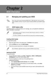
... any of the original motherboard BIOS file to a USB flash disk in case you need to download then click Next. 2-1 ASUS P5G41T-M LX2 Series Select the ASUS FTP site nearest you want to restore the BIOS in the future. The Drivers menu appears. 2. Updating the BIOS To update...complete the installation. Quit all Windows® applications before you to avoid network traffic, or click Auto Select then click Next. Installing ASUS Update To install ASUS Update: 1. Select Update BIOS from the Internet a. b. Place the support DVD in the support DVD that allows you update the...
... any of the original motherboard BIOS file to a USB flash disk in case you need to download then click Next. 2-1 ASUS P5G41T-M LX2 Series Select the ASUS FTP site nearest you want to restore the BIOS in the future. The Drivers menu appears. 2. Updating the BIOS To update...complete the installation. Quit all Windows® applications before you to avoid network traffic, or click Auto Select then click Next. Installing ASUS Update To install ASUS Update: 1. Select Update BIOS from the Internet a. b. Place the support DVD in the support DVD that allows you update the...
User Manual
Page 28
... system off the system after the utility completes the updating process and turn on . Download the latest BIOS file from the ASUS website at startup: • Press during the updating process. The BIOS screens include navigation keys and brief online help to ... this utility, rename the BIOS file in the removable device into PG41TML2.ROM (P5G41T-M LX2) / PG41TMLG.ROM (P5G41T-M LX2/GB) / PG41TMLP.ROM (P5G41T-M LX2/GB/LPT). • The BIOS file in using the first two options. 2-3 ASUS P5G41T-M LX2 Series Doing so can restore a corrupted BIOS file using the motherboard support DVD ...
... system off the system after the utility completes the updating process and turn on . Download the latest BIOS file from the ASUS website at startup: • Press during the updating process. The BIOS screens include navigation keys and brief online help to ... this utility, rename the BIOS file in the removable device into PG41TML2.ROM (P5G41T-M LX2) / PG41TMLG.ROM (P5G41T-M LX2/GB) / PG41TMLP.ROM (P5G41T-M LX2/GB/LPT). • The BIOS file in using the first two options. 2-3 ASUS P5G41T-M LX2 Series Doing so can restore a corrupted BIOS file using the motherboard support DVD ...
User Manual
Page 30
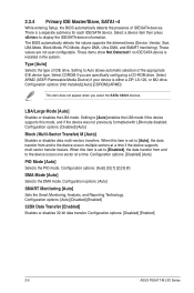
... then press to Auto allows automatic selection of the appropriate IDE device type. These values are specifically configuring a CD-ROM drive. Configuration options: [Disabled] [Enabled] 2-5 ASUS P5G41T-M LX2 Series These items show Not Detected if no IDE/SATA device is either a ZIP, LS-120, or MO drive. Configuration options: [Not Installed] [Auto] [CDROM...
... then press to Auto allows automatic selection of the appropriate IDE device type. These values are specifically configuring a CD-ROM drive. Configuration options: [Disabled] [Enabled] 2-5 ASUS P5G41T-M LX2 Series These items show Not Detected if no IDE/SATA device is either a ZIP, LS-120, or MO drive. Configuration options: [Not Installed] [Auto] [CDROM...
User Manual
Page 32
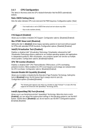
.... 2.4.1 CPU Configuration The items in this menu show the CPU-related information that supports the Enhanced Intel SpeedStep® Technology (EIST). Configuration options: [Enabled] [Disabled] 2-7 ASUS P5G41T-M LX2 Series Configuration options: [Disabled] [Enabled] The following item appears only when you to enable or disable C1E Support. Configuration options: [Disabled] [Enabled] Max CPUID Value...
.... 2.4.1 CPU Configuration The items in this menu show the CPU-related information that supports the Enhanced Intel SpeedStep® Technology (EIST). Configuration options: [Enabled] [Disabled] 2-7 ASUS P5G41T-M LX2 Series Configuration options: [Disabled] [Enabled] The following item appears only when you to enable or disable C1E Support. Configuration options: [Disabled] [Enabled] Max CPUID Value...
User Manual
Page 34
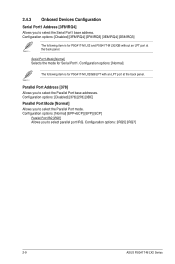
... Address [378] Allows you to select the Parallel Port mode. Configuration options: [Normal] The following item is for P5G41T-M LX2/GB/LPT with an LPT port at the back panel. Configuration options: [IRQ5] [IRQ7] 2-9 ASUS P5G41T-M LX2 Series Configuration options: [Disabled] [378] [278] [3BC] Parallel Port Mode [Normal] Allows you to select the Parallel Port...
... Address [378] Allows you to select the Parallel Port mode. Configuration options: [Normal] The following item is for P5G41T-M LX2/GB/LPT with an LPT port at the back panel. Configuration options: [IRQ5] [IRQ7] 2-9 ASUS P5G41T-M LX2 Series Configuration options: [Disabled] [378] [278] [3BC] Parallel Port Mode [Normal] Allows you to select the Parallel Port...
User Manual
Page 36
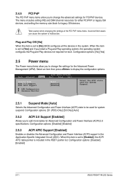
... you install a Plug and Play operating system, the operating system configures the Plug and Play devices not required for boot. Configuration options: [Disabled] [Enabled] 2-11 ASUS P5G41T-M LX2 Series 2.4.5 PCI PnP The PCI PnP menu items allow you to add more tables for Advanced Configuration and Power Interface (ACPI) 2.0 specifications. Select an item...
... you install a Plug and Play operating system, the operating system configures the Plug and Play devices not required for boot. Configuration options: [Disabled] [Enabled] 2-11 ASUS P5G41T-M LX2 Series 2.4.5 PCI PnP The PCI PnP menu items allow you to add more tables for Advanced Configuration and Power Interface (ACPI) 2.0 specifications. Select an item...
User Manual
Page 38
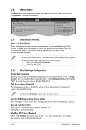
... [Removable Dev.] [Hard Drive] [ATAPI CD-ROM] [Disabled] • To select the boot device during system startup, press when ASUS Logo appears. • To access Windows® OS in the system. Select an item then press to display the submenu. The number ... Press after POST. 2.6.2 Boot Settings Configuration Quick Boot [Enabled] Enabling this item to [Enabled] to use the ASUS MyLogo2™ feature. Configuration options: [Disabled] [Enabled] 2-13 ASUS P5G41T-M LX2 Series A virtual floppy disk drive (Floppy Drive B: ) may appear when you to enable or disable the full screen...
... [Removable Dev.] [Hard Drive] [ATAPI CD-ROM] [Disabled] • To select the boot device during system startup, press when ASUS Logo appears. • To access Windows® OS in the system. Select an item then press to display the submenu. The number ... Press after POST. 2.6.2 Boot Settings Configuration Quick Boot [Enabled] Enabling this item to [Enabled] to use the ASUS MyLogo2™ feature. Configuration options: [Disabled] [Enabled] 2-13 ASUS P5G41T-M LX2 Series A virtual floppy disk drive (Floppy Drive B: ) may appear when you to enable or disable the full screen...
User Manual
Page 40
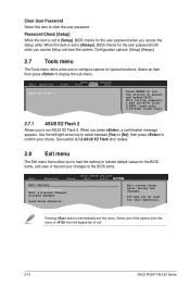
... & Discard Changes Discard Changes Load Setup Defaults BIOS SETUP UTILITY Boot Tools Exit ExEixtitsyssytsetmemsesteutpup afatfetrersasvaivnigngthtehe chcahnagnegse.s. F1F010kekyeycacnanbebeusuesded fofrorthtihsisopoepreartaitoino.n. Select+FFEEFFEo-11Sn11Sn0Ct0CeeorSSCGSEf eeheaxtSSGGSEhllanvieeoeaxeeeneetllnviccgroeeteettteaapccorlntttaaioSIOdSlnnctpHSIudsreteEctbHemilxfre-eEreopioemslxnntmecpinrtteheisn 2-15 ASUS P5G41T-M LX2 Series Configuration options: [Setup] [Always] 2.7 Tools menu The Tools menu items allow you to load the optimal or failsafe default values for the BIOS...
... & Discard Changes Discard Changes Load Setup Defaults BIOS SETUP UTILITY Boot Tools Exit ExEixtitsyssytsetmemsesteutpup afatfetrersasvaivnigngthtehe chcahnagnegse.s. F1F010kekyeycacnanbebeusuesded fofrorthtihsisopoepreartaitoino.n. Select+FFEEFFEo-11Sn11Sn0Ct0CeeorSSCGSEf eeheaxtSSGGSEhllanvieeoeaxeeeneetllnviccgroeeteettteaapccorlntttaaioSIOdSlnnctpHSIudsreteEctbHemilxfre-eEreopioemslxnntmecpinrtteheisn 2-15 ASUS P5G41T-M LX2 Series Configuration options: [Setup] [Always] 2.7 Tools menu The Tools menu items allow you to load the optimal or failsafe default values for the BIOS...


