
User Manual
Page 8
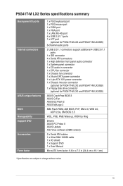
... P5G41T-M LX2/GB/LPT: Realtek® RTL8112L Gigabit Ethernet PCIe controller P5G41T-M LX2: Realtek® RTL8103EL 10/100Mbps Ethernet PCIe controller VIA® VT1705 High Definition Audio 6-channel CODEC Supports Multi-streaming technology Supports up to 8GB system memory * Refer to www.asus.com for... / Celeron® processors Supports Intel® 45nm multi-core CPU Supports Intel® Hyper-Threading Technology and Enhanced Intel SpeedStep® Technology (EIST) * Refer to www.asus.com for the Intel® CPU support list. resolution of 1759MB Supports RGB with max. Northbridge...
... P5G41T-M LX2/GB/LPT: Realtek® RTL8112L Gigabit Ethernet PCIe controller P5G41T-M LX2: Realtek® RTL8103EL 10/100Mbps Ethernet PCIe controller VIA® VT1705 High Definition Audio 6-channel CODEC Supports Multi-streaming technology Supports up to 8GB system memory * Refer to www.asus.com for... / Celeron® processors Supports Intel® 45nm multi-core CPU Supports Intel® Hyper-Threading Technology and Enhanced Intel SpeedStep® Technology (EIST) * Refer to www.asus.com for the Intel® CPU support list. resolution of 1759MB Supports RGB with max. Northbridge...
User Manual
Page 9
... connector 1 x System panel connector 1 x CD audio-in connector 1 x CPU fan connector 1 x Chassis fan connector 1 x 24-pin EATX power connector 1 x 4-pin ATX 12V power connector 1 x Chassis intrusion connector (optional for P5G41T-M LX2 and P5G41T-M LX2/GB) 1 x Floppy disk drive connector (optional for P5G41T-M LX2 and P5G41T-M LX2/GB) ASUS CrashFree BIOS 3 ASUS Q-Fan ASUS EZ Flash 2 ASUS MyLogo 2 8Mb Flash ROM, AMI BIOS, PnP, DMI 2.0, WfM...
... connector 1 x System panel connector 1 x CD audio-in connector 1 x CPU fan connector 1 x Chassis fan connector 1 x 24-pin EATX power connector 1 x 4-pin ATX 12V power connector 1 x Chassis intrusion connector (optional for P5G41T-M LX2 and P5G41T-M LX2/GB) 1 x Floppy disk drive connector (optional for P5G41T-M LX2 and P5G41T-M LX2/GB) ASUS CrashFree BIOS 3 ASUS Q-Fan ASUS EZ Flash 2 ASUS MyLogo 2 8Mb Flash ROM, AMI BIOS, PnP, DMI 2.0, WfM...
User Manual
Page 16
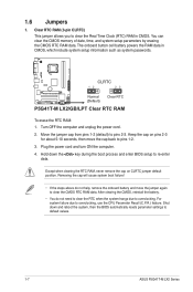
...by erasing the CMOS RTC RAM data. Move the jumper cap from pins 1-2 (default) to default values. 1-7 ASUS P5G41T-M LX2 Series CLRTC 12 23 P5G41T-M LX2/GB/LPT Normal (Default) Clear RTC P5G41T-M LX2/GB/LPT Clear RTC RAM To erase the RTC RAM: 1. Keep the cap on CLRTC jumper default position. After ...clearing the RTC RAM, never remove the cap on pins 2-3 for about 5-10 seconds, then move the jumper again to overclocking, use the CPU Parameter Recall (C.P.R.) feature. Clear RTC RAM (3-pin CLRTC) This jumper allows you to re-enter data. Turn OFF the computer and unplug ...
...by erasing the CMOS RTC RAM data. Move the jumper cap from pins 1-2 (default) to default values. 1-7 ASUS P5G41T-M LX2 Series CLRTC 12 23 P5G41T-M LX2/GB/LPT Normal (Default) Clear RTC P5G41T-M LX2/GB/LPT Clear RTC RAM To erase the RTC RAM: 1. Keep the cap on CLRTC jumper default position. After ...clearing the RTC RAM, never remove the cap on pins 2-3 for about 5-10 seconds, then move the jumper again to overclocking, use the CPU Parameter Recall (C.P.R.) feature. Clear RTC RAM (3-pin CLRTC) This jumper allows you to re-enter data. Turn OFF the computer and unplug ...
User Manual
Page 17
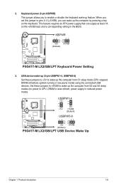
...on the keyboard. KBPWR 12 23 +5V +5VSB (Default) P5G41T-M LX2/GB/LPT P5G41T-M LX2/GB/LPT Keyboard Power Setting 3. USBPW1-4 12 23 +5V +5VSB (Default) USBPW5-8 P5G41T-M LX2/GB/LPT 12 23 +5V +5VSB (Default) P5G41T-M LX2/GB/LPT USB Device Wake Up Chapter 1: Product introduction 1-8 This ...feature requires an ATX power supply that can wake up the computer from S3 and S4 sleep modes (no power to wake up feature. USB device wake-up (3-pin USBPW1-4, USBPW5-8) Set these jumpers to +5VSB to CPU...
...on the keyboard. KBPWR 12 23 +5V +5VSB (Default) P5G41T-M LX2/GB/LPT P5G41T-M LX2/GB/LPT Keyboard Power Setting 3. USBPW1-4 12 23 +5V +5VSB (Default) USBPW5-8 P5G41T-M LX2/GB/LPT 12 23 +5V +5VSB (Default) P5G41T-M LX2/GB/LPT USB Device Wake Up Chapter 1: Product introduction 1-8 This ...feature requires an ATX power supply that can wake up the computer from S3 and S4 sleep modes (no power to wake up feature. USB device wake-up (3-pin USBPW1-4, USBPW5-8) Set these jumpers to +5VSB to CPU...
User Manual
Page 20
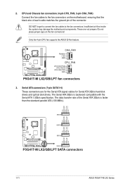
...CPU fan supports the ASUS Q-Fan feature. GND RSATA_RXN4 RSATA_RXP4 GND RSATA_TXN4 RSATA_TXP4 GND SATA4 GND RSATA_RXN3 RSATA_RXP3 GND RSATA_TXN3 RSATA_TXP3 GND SATA3 GND RSATA_RXN2 RSATA_RXP2 GND RSATA_TXN2 RSATA_TXP2 GND GND RSATA_RXN1 RSATA_RXP1 GND RSATA_TXN1 RSATA_TXP1 GND P5G41T-M LX2/GB/LPT SATA2 SATA1 P5G41T-M LX2/GB/LPT SATA connectors 1-11 ASUS P5G41T-M LX2...connectors. The data transfer rate of the connector. P5G41T-M LX2/GB/LPT CHA_FAN Rotation +12V GND CPU_FAN CPU FAN PWM CPU FAN IN CPU FAN PWR GND P5G41T-M LX2/GB/LPT fan connectors 3. Do not place jumper caps...
...CPU fan supports the ASUS Q-Fan feature. GND RSATA_RXN4 RSATA_RXP4 GND RSATA_TXN4 RSATA_TXP4 GND SATA4 GND RSATA_RXN3 RSATA_RXP3 GND RSATA_TXN3 RSATA_TXP3 GND SATA3 GND RSATA_RXN2 RSATA_RXP2 GND RSATA_TXN2 RSATA_TXP2 GND GND RSATA_RXN1 RSATA_RXP1 GND RSATA_TXN1 RSATA_TXP1 GND P5G41T-M LX2/GB/LPT SATA2 SATA1 P5G41T-M LX2/GB/LPT SATA connectors 1-11 ASUS P5G41T-M LX2...connectors. The data transfer rate of the connector. P5G41T-M LX2/GB/LPT CHA_FAN Rotation +12V GND CPU_FAN CPU FAN PWM CPU FAN IN CPU FAN PWR GND P5G41T-M LX2/GB/LPT fan connectors 3. Do not place jumper caps...


