User Manual
Page 2
... General Public License ("GPL") and under various Free Open Source Software licenses. SPECIFICATIONS AND INFORMATION CONTAINED IN THIS MANUAL ARE FURNISHED FOR INFORMATIONAL USE ONLY, AND ARE SUBJECT TO CHANGE AT ANY TIME WITHOUT NOTICE, AND SHOULD NOT BE CONSTRUED AS A COMMITMENT BY ASUS. Offer to Provide Source Code of Certain Software This product may be no earlier than...
... General Public License ("GPL") and under various Free Open Source Software licenses. SPECIFICATIONS AND INFORMATION CONTAINED IN THIS MANUAL ARE FURNISHED FOR INFORMATIONAL USE ONLY, AND ARE SUBJECT TO CHANGE AT ANY TIME WITHOUT NOTICE, AND SHOULD NOT BE CONSTRUED AS A COMMITMENT BY ASUS. Offer to Provide Source Code of Certain Software This product may be no earlier than...

User Manual
Page 3
... guide vi P5G41T-M LX2 Series specifications summary viii Chapter 1: Product introduction 1.1 Before you proceed 1-1 1.2 Motherboard overview 1-2 1.2.1 Motherboard layout 1-2 1.2.2 Layout contents 1-3 1.3 Central Processing Unit (CPU 1-3 1.4 System memory 1-4 1.4.1 Overview 1-4 1.4.2 Memory configurations 1-4 1.5 Expansion slots 1-6 1.5.1 Installing an expansion card 1-6 1.5.2 Configuring an expansion card 1-6 1.5.3 PCI slots 1-6 1.5.4 PCI Express x16 slot 1-6 1.6 Jumpers 1-7 1.7 Connectors 1-9 1.7.1 Rear panel ports 1-9 1.7.2 Internal connectors 1-10 1.8 Software support...
... guide vi P5G41T-M LX2 Series specifications summary viii Chapter 1: Product introduction 1.1 Before you proceed 1-1 1.2 Motherboard overview 1-2 1.2.1 Motherboard layout 1-2 1.2.2 Layout contents 1-3 1.3 Central Processing Unit (CPU 1-3 1.4 System memory 1-4 1.4.1 Overview 1-4 1.4.2 Memory configurations 1-4 1.5 Expansion slots 1-6 1.5.1 Installing an expansion card 1-6 1.5.2 Configuring an expansion card 1-6 1.5.3 PCI slots 1-6 1.5.4 PCI Express x16 slot 1-6 1.6 Jumpers 1-7 1.7 Connectors 1-9 1.7.1 Rear panel ports 1-9 1.7.2 Internal connectors 1-10 1.8 Software support...

User Manual
Page 8
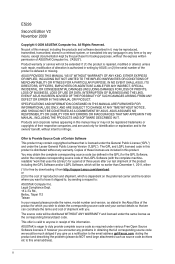
... 1 x PCIe x16 slot 1 x PCIe x1 slot (optional) 2 x PCI slots 1 x Ultra DMA 100/66 connector 4 x Serial ATA 3Gb/s ports P5G41T-M LX2/GB and P5G41T-M LX2/GB/LPT: Realtek® RTL8112L Gigabit Ethernet PCIe controller P5G41T-M LX2: Realtek® RTL8103EL 10/100Mbps Ethernet PCIe controller VIA® VT1705 High Definition Audio 6-channel CODEC Supports Multi-streaming technology Supports up to 8GB system memory * Refer to www.asus.com for the latest Memory QVL (Qualified Vendors Lists). ** When you are using a Windows® 32-bit operating system. shared memory...
... 1 x PCIe x16 slot 1 x PCIe x1 slot (optional) 2 x PCI slots 1 x Ultra DMA 100/66 connector 4 x Serial ATA 3Gb/s ports P5G41T-M LX2/GB and P5G41T-M LX2/GB/LPT: Realtek® RTL8112L Gigabit Ethernet PCIe controller P5G41T-M LX2: Realtek® RTL8103EL 10/100Mbps Ethernet PCIe controller VIA® VT1705 High Definition Audio 6-channel CODEC Supports Multi-streaming technology Supports up to 8GB system memory * Refer to www.asus.com for the latest Memory QVL (Qualified Vendors Lists). ** When you are using a Windows® 32-bit operating system. shared memory...
User Manual
Page 9
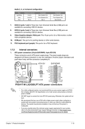
...pin ATX 12V power connector 1 x Chassis intrusion connector (optional for P5G41T-M LX2 and P5G41T-M LX2/GB) 1 x Floppy disk drive connector (optional for P5G41T-M LX2 and P5G41T-M LX2/GB) ASUS CrashFree BIOS 3 ASUS Q-Fan ASUS EZ Flash 2 ASUS MyLogo 2 8Mb Flash ROM, AMI BIOS, PnP, DMI 2.0, WfM 2.0, ACPI 2.0a, SM BIOS 2.5 WOL, PXE, PME Wake up, WOR by Ring Drivers ASUS PC Probe II ASUS Update Anti-Virus software (OEM version) 2 x Serial ATA cables 1 x Ultra DMA 100/66 cable 1 x I/O shield 1 x Support DVD 1 x User Manual MicroATX form factor: 9.6 in x 7.5 in (24.4 cm x 19.1 cm) * Specifications...
...pin ATX 12V power connector 1 x Chassis intrusion connector (optional for P5G41T-M LX2 and P5G41T-M LX2/GB) 1 x Floppy disk drive connector (optional for P5G41T-M LX2 and P5G41T-M LX2/GB) ASUS CrashFree BIOS 3 ASUS Q-Fan ASUS EZ Flash 2 ASUS MyLogo 2 8Mb Flash ROM, AMI BIOS, PnP, DMI 2.0, WfM 2.0, ACPI 2.0a, SM BIOS 2.5 WOL, PXE, PME Wake up, WOR by Ring Drivers ASUS PC Probe II ASUS Update Anti-Virus software (OEM version) 2 x Serial ATA cables 1 x Ultra DMA 100/66 cable 1 x I/O shield 1 x Support DVD 1 x User Manual MicroATX form factor: 9.6 in x 7.5 in (24.4 cm x 19.1 cm) * Specifications...
User Manual
Page 15
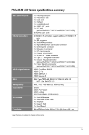
... the card. 3. When using PCI cards on the slot. 5. Align the card connector with it by adjusting the software settings. 1. See Chapter 2 for the card. 2. Otherwise, conflicts will arise between the two PCI groups, making the system unstable and the card inoperable. 1.5.3 PCI slots The PCI slot supports cards such as a LAN card, SCSI card, USB card, and other cards that comply with the PCI Express specifications. Unplug the power cord before adding or removing expansion cards. Replace the system cover. 1.5.2 Configuring...
... the card. 3. When using PCI cards on the slot. 5. Align the card connector with it by adjusting the software settings. 1. See Chapter 2 for the card. 2. Otherwise, conflicts will arise between the two PCI groups, making the system unstable and the card inoperable. 1.5.3 PCI slots The PCI slot supports cards such as a LAN card, SCSI card, USB card, and other cards that comply with the PCI Express specifications. Unplug the power cord before adding or removing expansion cards. Replace the system cover. 1.5.2 Configuring...
User Manual
Page 17
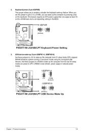
... to enable or disable the keyboard wake-up the computer from S3 and S4 sleep modes (no power to wake up the computer by pressing a key on the +5VSB lead, and a corresponding setting in reduced power mode). 2. KBPWR 12 23 +5V +5VSB (Default) P5G41T-M LX2/GB/LPT P5G41T-M LX2/GB/LPT Keyboard Power Setting 3. USB device wake-up (3-pin USBPW1-4, USBPW5-8) Set these jumpers to +5VSB to CPU, DRAM in slow refresh, power supply in the BIOS. USBPW1-4 12 23 +5V +5VSB (Default) USBPW5-8 P5G41T-M LX2/GB...
... to enable or disable the keyboard wake-up the computer from S3 and S4 sleep modes (no power to wake up the computer by pressing a key on the +5VSB lead, and a corresponding setting in reduced power mode). 2. KBPWR 12 23 +5V +5VSB (Default) P5G41T-M LX2/GB/LPT P5G41T-M LX2/GB/LPT Keyboard Power Setting 3. USB device wake-up (3-pin USBPW1-4, USBPW5-8) Set these jumpers to +5VSB to CPU, DRAM in slow refresh, power supply in the BIOS. USBPW1-4 12 23 +5V +5VSB (Default) USBPW5-8 P5G41T-M LX2/GB...
User Manual
Page 18
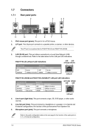
... Speaker Out. 6. This 25-pin port connects to the audio configuration table on the next page for P5G41T-M LX2 and P5G41T-M LX2/GB. 3. The LPT port is for the LAN port LED indications. LAN (RJ-45) port. This port allows connection to the table below for a PS/2 mouse. 2. This port connects a microphone. PS/2 mouse port (green). Line In port (light blue). In 4-channel and 6-channel configurations, the function of the audio ports in 2, 4, or 6-channel configuration. 1-9 ASUS P5G41T-M LX2 Series Refer to a Local Area Network (LAN) through a network...
... Speaker Out. 6. This 25-pin port connects to the audio configuration table on the next page for P5G41T-M LX2 and P5G41T-M LX2/GB. 3. The LPT port is for the LAN port LED indications. LAN (RJ-45) port. This port allows connection to the table below for a PS/2 mouse. 2. This port connects a microphone. PS/2 mouse port (green). Line In port (light blue). In 4-channel and 6-channel configurations, the function of the audio ports in 2, 4, or 6-channel configuration. 1-9 ASUS P5G41T-M LX2 Series Refer to a Local Area Network (LAN) through a network...
User Manual
Page 19
... not boot. • We recommend that you use a power supply unit (PSU) that you are for a PS/2 keyboard. 1.7.2 Internal connectors 1. These two 4-pin Universal Serial Bus (USB) ports are available for pointing devices or other VGA-compatible devices. 10. Video Graphics Adapter (VGA) port. This port is for connecting USB 2.0 devices. 8. The power supply plugs are designed to the Recommended Power Supply Wattage Calculator at http://support.asus. Audio 2, 4, or 6-channel configuration Port Light Blue Lime Pink Headset 2-channel Line In Line Out Mic In 4-channel Rear Speaker...
... not boot. • We recommend that you use a power supply unit (PSU) that you are for a PS/2 keyboard. 1.7.2 Internal connectors 1. These two 4-pin Universal Serial Bus (USB) ports are available for pointing devices or other VGA-compatible devices. 10. Video Graphics Adapter (VGA) port. This port is for connecting USB 2.0 devices. 8. The power supply plugs are designed to the Recommended Power Supply Wattage Calculator at http://support.asus. Audio 2, 4, or 6-channel configuration Port Light Blue Lime Pink Headset 2-channel Line In Line Out Mic In 4-channel Rear Speaker...
User Manual
Page 20
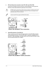
... P5G41T-M LX2/GB/LPT SATA2 SATA1 P5G41T-M LX2/GB/LPT SATA connectors 1-11 ASUS P5G41T-M LX2 Series The Serial ATA 3Gb/s is faster than the standard parallel ATA (133 MB/s). Only the 4-pin CPU fan supports the ASUS Q-Fan feature. Do not place jumper caps on the motherboard, ensuring that the black wire of each cable matches the ground pin of the Serial ATA 3Gb/s is backward compatible with the Serial ATA 1.5Gb/s specification. 2. CPU and Chassis fan connectors (4-pin CPU_FAN, 3-pin CHA_FAN) Connect the fan cables...
... P5G41T-M LX2/GB/LPT SATA2 SATA1 P5G41T-M LX2/GB/LPT SATA connectors 1-11 ASUS P5G41T-M LX2 Series The Serial ATA 3Gb/s is faster than the standard parallel ATA (133 MB/s). Only the 4-pin CPU fan supports the ASUS Q-Fan feature. Do not place jumper caps on the motherboard, ensuring that the black wire of each cable matches the ground pin of the Serial ATA 3Gb/s is backward compatible with the Serial ATA 1.5Gb/s specification. 2. CPU and Chassis fan connectors (4-pin CPU_FAN, 3-pin CHA_FAN) Connect the fan cables...

User Manual
Page 25
... you install Windows® XP Service Pack 3 or later versions / Windows® Vista Service Pack 1 or later versions before installing the drivers for better compatibility and system stability. 1.8.2 Support DVD information The Support DVD that comes with the motherboard package contains the drivers, software applications, and utilities that you can install to locate the file ASSETUP.EXE from the BIN folder. Refer to your computer. To run the DVD. The DVD automatically displays the Drivers menu...
... you install Windows® XP Service Pack 3 or later versions / Windows® Vista Service Pack 1 or later versions before installing the drivers for better compatibility and system stability. 1.8.2 Support DVD information The Support DVD that comes with the motherboard package contains the drivers, software applications, and utilities that you can install to locate the file ASSETUP.EXE from the BIN folder. Refer to your computer. To run the DVD. The DVD automatically displays the Drivers menu...
User Manual
Page 26
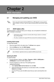
... Service Provider (ISP). • This utility is available in the support DVD that you want to complete the installation. From the Windows® desktop, click Start > Programs > ASUS > ASUSUpdate > ASUSUpdate to avoid network traffic, or click Auto Select then click Next. Installing ASUS Update To install ASUS Update: 1. Follow the onscreen instructions to download then click Next. 2-1 ASUS P5G41T-M LX2 Series Updating the BIOS To update the BIOS: 1. From the dropdown list, select any of the original motherboard BIOS file to a USB flash disk...
... Service Provider (ISP). • This utility is available in the support DVD that you want to complete the installation. From the Windows® desktop, click Start > Programs > ASUS > ASUSUpdate > ASUSUpdate to avoid network traffic, or click Auto Select then click Next. Installing ASUS Update To install ASUS Update: 1. Follow the onscreen instructions to download then click Next. 2-1 ASUS P5G41T-M LX2 Series Updating the BIOS To update the BIOS: 1. From the dropdown list, select any of the original motherboard BIOS file to a USB flash disk...
User Manual
Page 27
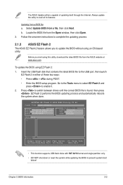
... to prevent system boot failure! Locate the BIOS file from the ASUS website at www.asus.com. ASUSTek EZ Flash 2 BIOS ROM Utility V3.44 FLASH TYPE: MXIC 25L8005 Current ROM BOARD:P5G41T-M LX2/GB/LPT VER:0305 (H:00 B:00) DATE: 10/29/2009 Update ROM BOARD: Unknown VER: Unknown DATE: Unknown PATH: A:\ A: Note [Enter] Select or Load [Tab] Switch [Up/Down/Home/End] Move [B] Backup [V] Drive Info [ESC] Exit • This function supports USB flash disks with FAT...
... to prevent system boot failure! Locate the BIOS file from the ASUS website at www.asus.com. ASUSTek EZ Flash 2 BIOS ROM Utility V3.44 FLASH TYPE: MXIC 25L8005 Current ROM BOARD:P5G41T-M LX2/GB/LPT VER:0305 (H:00 B:00) DATE: 10/29/2009 Update ROM BOARD: Unknown VER: Unknown DATE: Unknown PATH: A:\ A: Note [Enter] Select or Load [Tab] Switch [Up/Down/Home/End] Move [B] Backup [V] Drive Info [ESC] Exit • This function supports USB flash disks with FAT...
User Manual
Page 28
... utility, rename the BIOS file in the removable device into PG41TML2.ROM (P5G41T-M LX2) / PG41TMLG.ROM (P5G41T-M LX2/GB) / PG41TMLP.ROM (P5G41T-M LX2/GB/LPT). • The BIOS file in using this option only if you in the support DVD may not be the latest version. Select the Load Setup Defaults item under the Exit menu. Entering BIOS Setup at startup To enter BIOS Setup at www.asus.com. • The removable devices that allows you do not press , POST continues with motherboard models. Do this utility. The BIOS screens include navigation keys...
... utility, rename the BIOS file in the removable device into PG41TML2.ROM (P5G41T-M LX2) / PG41TMLG.ROM (P5G41T-M LX2/GB) / PG41TMLP.ROM (P5G41T-M LX2/GB/LPT). • The BIOS file in using this option only if you in the support DVD may not be the latest version. Select the Load Setup Defaults item under the Exit menu. Entering BIOS Setup at startup To enter BIOS Setup at www.asus.com. • The removable devices that allows you do not press , POST continues with motherboard models. Do this utility. The BIOS screens include navigation keys...
User Manual
Page 29
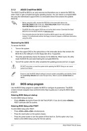
Using the power button, reset button, or the ++ keys to force reset from the operating system. • The default BIOS settings for this motherboard apply for P5G41T-M LX2/GB/LPT only. Select the Load Setups Default item under the Exit Menu. Chapter 2: BIOS information 2-4 We recommend to always shut down the system properly from a running operating system can cause damage to your screen. • Visit the ASUS website at www.asus.com to...
Using the power button, reset button, or the ++ keys to force reset from the operating system. • The default BIOS settings for this motherboard apply for P5G41T-M LX2/GB/LPT only. Select the Load Setups Default item under the Exit Menu. Chapter 2: BIOS information 2-4 We recommend to always shut down the system properly from a running operating system can cause damage to your screen. • Visit the ASUS website at www.asus.com to...
User Manual
Page 30
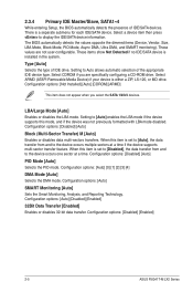
...] [Enabled] 2-5 ASUS P5G41T-M LX2 Series Select a device item then press to [Auto] enables the LBA mode if the device supports this item is installed in the system. The BIOS automatically detects the values opposite the dimmed items (Device, Vendor, Size, LBA Mode, Block Mode, PIO Mode, Async DMA, Ultra DMA, and SMART monitoring). Configuration options: [Disabled] [Auto] PIO Mode [Auto] Selects the PIO mode. Configuration options: [Auto] [Disabled] [Enabled] 32Bit Data Transfer [Enabled] Enables or disables 32-bit data transfer. Select CDROM if you select the SATA 1/2/3/4 devices...
...] [Enabled] 2-5 ASUS P5G41T-M LX2 Series Select a device item then press to [Auto] enables the LBA mode if the device supports this item is installed in the system. The BIOS automatically detects the values opposite the dimmed items (Device, Vendor, Size, LBA Mode, Block Mode, PIO Mode, Async DMA, Ultra DMA, and SMART monitoring). Configuration options: [Disabled] [Auto] PIO Mode [Auto] Selects the PIO mode. Configuration options: [Auto] [Disabled] [Enabled] 32Bit Data Transfer [Enabled] Enables or disables 32-bit data transfer. Select CDROM if you select the SATA 1/2/3/4 devices...
User Manual
Page 31
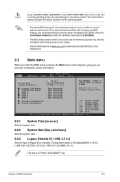
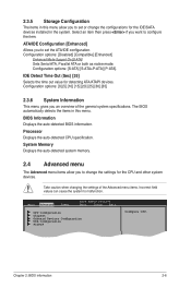
...Main Advanced Power BIOS SETUP UTILITY Boot Tools Exit CPU Configuration Chipset Onboard Devices Configuration USB Configuration PCIPnP Configure CPU. 2.3.5 Storage Configuration The items in this menu. ATA/IDE Configuration [Enhanced] Allows you to set the ATA/IDE configuration. Configuration options: [0] [5] [10] [15] [20] [25] [30] [35] 2.3.6 System Information This menu gives you to malfunction. System Memory Displays the auto-detected system memory. 2.4 Advanced menu The Advanced menu items allow you to configure the item. Take caution when changing the settings...
...Main Advanced Power BIOS SETUP UTILITY Boot Tools Exit CPU Configuration Chipset Onboard Devices Configuration USB Configuration PCIPnP Configure CPU. 2.3.5 Storage Configuration The items in this menu. ATA/IDE Configuration [Enhanced] Allows you to set the ATA/IDE configuration. Configuration options: [0] [5] [10] [15] [20] [25] [30] [35] 2.3.6 System Information This menu gives you to malfunction. System Memory Displays the auto-detected system memory. 2.4 Advanced menu The Advanced menu items allow you to configure the item. Take caution when changing the settings...
User Manual
Page 33
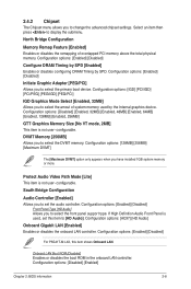
...not user- Protect Audio Video Path Mode [Lite] This item is not user- configurable. Configuration options: [Disabled] [Enabled] Chapter 2: BIOS information 2-8 North Bridge Configuration Memory Remap Feature [Enabled] Enables or disables the remapping of system memory used , set the audio controller. Configuration options: [Enabled] [Disabled] Initiate Graphic Adapter [PEG/PCI] Allows you to display the submenu. DVMT Memory [256MB] Allows you to change the advanced chipset settings. Onboard LAN Boot ROM [Disabled] Enables or disables the boot ROM in the onboard LAN controller...
...not user- Protect Audio Video Path Mode [Lite] This item is not user- configurable. Configuration options: [Disabled] [Enabled] Chapter 2: BIOS information 2-8 North Bridge Configuration Memory Remap Feature [Enabled] Enables or disables the remapping of system memory used , set the audio controller. Configuration options: [Enabled] [Disabled] Initiate Graphic Adapter [PEG/PCI] Allows you to display the submenu. DVMT Memory [256MB] Allows you to change the advanced chipset settings. Onboard LAN Boot ROM [Disabled] Enables or disables the boot ROM in the onboard LAN controller...

User Manual
Page 35
... plugged in HiSpeed (480Mbps) or Full Speed (12Mbps). If no USB device is detected, the legacy USB support is detected, the item shows None. Configuration options: [10 Sec] [20 Sec] [30 Sec] [40 Sec] Emulation Type [Auto] Allows you to change the USB-related features. The Module Version and USB Devices Enabled items show the auto-detected values. Configuration options: [Auto] [Floppy] [Forced FDD] [Hard Disk] [CDROM] Chapter 2: BIOS information 2-10 Configuration options: [Disabled] [Enabled] [Auto] USB 2.0 Controller Mode [HiSpeed] Allows you to display...
... plugged in HiSpeed (480Mbps) or Full Speed (12Mbps). If no USB device is detected, the legacy USB support is detected, the item shows None. Configuration options: [10 Sec] [20 Sec] [30 Sec] [40 Sec] Emulation Type [Auto] Allows you to change the USB-related features. The Module Version and USB Devices Enabled items show the auto-detected values. Configuration options: [Auto] [Floppy] [Forced FDD] [Hard Disk] [CDROM] Chapter 2: BIOS information 2-10 Configuration options: [Disabled] [Enabled] [Auto] USB 2.0 Controller Mode [HiSpeed] Allows you to display...
User Manual
Page 36
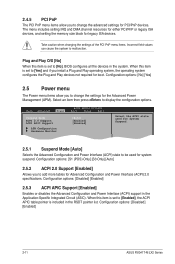
...Specific Integrated Circuit (ASIC). Main Advanced Power BIOS SETUP UTILITY Boot Tools Exit Suspend Mode [Auto] ACPI 2.0 Support [Enabled] ACPI APIC Support [Enabled] APM Configuration Hardware Monitor Select the ACPI state used for system suspend. Configuration options: [Disabled] [Enabled] 2.5.3 ACPI APIC Support [Enabled] Enables or disables the Advanced Configuration and Power Interface (ACPI) support in the RSDT pointer list. The menu includes setting IRQ and DMA channel resources for either PCI/PnP or legacy ISA devices, and setting the memory size block for PCI/PnP devices...
...Specific Integrated Circuit (ASIC). Main Advanced Power BIOS SETUP UTILITY Boot Tools Exit Suspend Mode [Auto] ACPI 2.0 Support [Enabled] ACPI APIC Support [Enabled] APM Configuration Hardware Monitor Select the ACPI state used for system suspend. Configuration options: [Disabled] [Enabled] 2.5.3 ACPI APIC Support [Enabled] Enables or disables the Advanced Configuration and Power Interface (ACPI) support in the RSDT pointer list. The menu includes setting IRQ and DMA channel resources for either PCI/PnP or legacy ISA devices, and setting the memory size block for PCI/PnP devices...
User Manual
Page 38
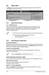
... error occurs. Configuration options: [Disabled] [Enabled] Set this item allows the BIOS to skip some power on the number of devices installed in Safe Mode, do any of device items that appears on the screen depends on self tests (POST) while booting to decrease the time needed to boot the system. Main Advanced Power BIOS SETUP UTILITY Boot Tools Exit Boot Settings Boot Device Priority Boot Settings Configuration Security Specifies the Boot Device Priority sequence. Configuration options: [Removable Dev.] [Hard Drive] [ATAPI CD-ROM] [Disabled] • To select the boot device...
... error occurs. Configuration options: [Disabled] [Enabled] Set this item allows the BIOS to skip some power on the number of devices installed in Safe Mode, do any of device items that appears on the screen depends on self tests (POST) while booting to decrease the time needed to boot the system. Main Advanced Power BIOS SETUP UTILITY Boot Tools Exit Boot Settings Boot Device Priority Boot Settings Configuration Security Specifies the Boot Device Priority sequence. Configuration options: [Removable Dev.] [Hard Drive] [ATAPI CD-ROM] [Disabled] • To select the boot device...


