
User Manual
Page 1
Motherboard P5G41T-M LX2 Series • P5G41T-M LX2 • P5G41T-M LX2/GB • P5G41T-M LX2/GB/LPT
Motherboard P5G41T-M LX2 Series • P5G41T-M LX2 • P5G41T-M LX2/GB • P5G41T-M LX2/GB/LPT

User Manual
Page 3
Contents Notices...v Safety information vi About this guide vi P5G41T-M LX2 Series specifications summary viii Chapter 1: Product introduction 1.1 Before you proceed 1-1 1.2 Motherboard overview 1-2 1.2.1 Motherboard layout 1-2 1.2.2 Layout contents 1-3 1.3 Central Processing Unit (CPU 1-3 1.4 System memory 1-4 1.4.1 Overview 1-4 1.4.2 ... 2: BIOS information 2.1 Managing and updating your BIOS 2-1 2.1.1 ASUS Update utility 2-1 2.1.2 ASUS EZ Flash 2 2-2 2.1.3 ASUS CrashFree BIOS 2-3 2.2 BIOS setup program 2-3 2.3 Main menu 2-4 2.3.1 System Time 2-4 2.3.2 System Date 2-4 iii
Contents Notices...v Safety information vi About this guide vi P5G41T-M LX2 Series specifications summary viii Chapter 1: Product introduction 1.1 Before you proceed 1-1 1.2 Motherboard overview 1-2 1.2.1 Motherboard layout 1-2 1.2.2 Layout contents 1-3 1.3 Central Processing Unit (CPU 1-3 1.4 System memory 1-4 1.4.1 Overview 1-4 1.4.2 ... 2: BIOS information 2.1 Managing and updating your BIOS 2-1 2.1.1 ASUS Update utility 2-1 2.1.2 ASUS EZ Flash 2 2-2 2.1.3 ASUS CrashFree BIOS 2-3 2.2 BIOS setup program 2-3 2.3 Main menu 2-4 2.3.1 System Time 2-4 2.3.2 System Date 2-4 iii
User Manual
Page 5
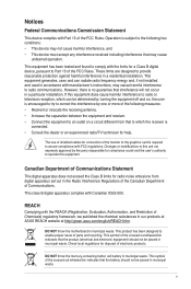
... crossed out wheeled bin indicates that to provide reasonable protection against harmful interference in a particular installation. DO NOT throw the motherboard in municipal waste. DO NOT throw the mercury-containing button cell battery in municipal waste. Notices Federal Communications Commission Statement This...; Connect the equipment to an outlet on a circuit different from digital apparatus set out in our products at ASUS REACH website at http://green.asus.com/english/REACH.htm. Operation is no guarantee that the battery should not be placed in municipal waste. However...
... crossed out wheeled bin indicates that to provide reasonable protection against harmful interference in a particular installation. DO NOT throw the motherboard in municipal waste. DO NOT throw the mercury-containing button cell battery in municipal waste. Notices Federal Communications Commission Statement This...; Connect the equipment to an outlet on a circuit different from digital apparatus set out in our products at ASUS REACH website at http://green.asus.com/english/REACH.htm. Operation is no guarantee that the battery should not be placed in municipal waste. However...

User Manual
Page 6
...all power cables from the existing system before you add a device. • Before connecting or removing signal cables from the motherboard, ensure that all power cables are unplugged. • Seek professional assistance before the signal cables are connected. Operation safety • ... or your retailer. If you are not sure about the voltage of the electrical outlet you need when installing and configuring the motherboard. About this guide is organized This guide contains the following parts: • Chapter 1: Product introduction This chapter describes the features...
...all power cables from the existing system before you add a device. • Before connecting or removing signal cables from the motherboard, ensure that all power cables are unplugged. • Seek professional assistance before the signal cables are connected. Operation safety • ... or your retailer. If you are not sure about the voltage of the electrical outlet you need when installing and configuring the motherboard. About this guide is organized This guide contains the following parts: • Chapter 1: Product introduction This chapter describes the features...
User Manual
Page 10
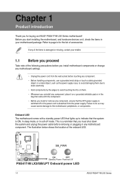
... any component, ensure that the ATX power supply is switched off mode. SB_PWR P5G41T-M LX2/GB/LPT ON OFF Standby Power Powered Off P5G41T-M LX2/GB/LPT Onboard power LED 1-1 ASUS P5G41T-M LX2 Series The illustration below shows the location of accessories. Before you start installing the motherboard, and hardware devices on a grounded antistatic pad or in the bag that...
... any component, ensure that the ATX power supply is switched off mode. SB_PWR P5G41T-M LX2/GB/LPT ON OFF Standby Power Powered Off P5G41T-M LX2/GB/LPT Onboard power LED 1-1 ASUS P5G41T-M LX2 Series The illustration below shows the location of accessories. Before you start installing the motherboard, and hardware devices on a grounded antistatic pad or in the bag that...

User Manual
Page 11
... Realtek® RTL8112L Gigabit Ethernet controller. • The floppy disk drive connector, chassis intrusion connector, and LPT port are optional items for P5G41T-M LX2 and P5G41T-M LX2/GB. Doing so can damage the motherboard. DO NOT overtighten the screws! Place six screws into the chassis in the correct orientation. The edge with external ports goes to...
... Realtek® RTL8112L Gigabit Ethernet controller. • The floppy disk drive connector, chassis intrusion connector, and LPT port are optional items for P5G41T-M LX2 and P5G41T-M LX2/GB. Doing so can damage the motherboard. DO NOT overtighten the screws! Place six screws into the chassis in the correct orientation. The edge with external ports goes to...

User Manual
Page 12
... 17. PCIe x16 / PCI slots 1-15 Page 1-7 1-13 1-1 1-14 1-13 1-12 1-14 1-6 1.3 Central Processing Unit (CPU) This motherboard comes with the Intel® Enhanced Intel SpeedStep® Technology (EIST) and Hyper-Threading Technology. 1-3 ASUS P5G41T-M LX2 Series SATA connectors (7-pin SATA1-4) 9. Floppy disk drive connector (34-1 pin FLOPPY) 1-4 15. Clear RTC RAM (3-pin CLRTC...
... 17. PCIe x16 / PCI slots 1-15 Page 1-7 1-13 1-1 1-14 1-13 1-12 1-14 1-6 1.3 Central Processing Unit (CPU) This motherboard comes with the Intel® Enhanced Intel SpeedStep® Technology (EIST) and Hyper-Threading Technology. 1-3 ASUS P5G41T-M LX2 Series SATA connectors (7-pin SATA1-4) 9. Floppy disk drive connector (34-1 pin FLOPPY) 1-4 15. Clear RTC RAM (3-pin CLRTC...
User Manual
Page 13
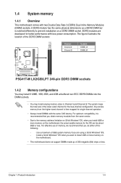
... memory if you want to prevent installation on the motherboard. • This motherboard does not support DIMMs made up of 256 megabits (Mb) chips or less. For effective use of the DDR3 DIMM sockets: DIMM_A1 DIMM_B1 Channel Channel A Channel B Sockets DIMM_A1 DIMM_B1 P5G41T-M LX2/GB/LPT P5G41T-M LX2/GB/LPT 240-pin DDR3 DIMM sockets 1.4.2 Memory configurations You...
... memory if you want to prevent installation on the motherboard. • This motherboard does not support DIMMs made up of 256 megabits (Mb) chips or less. For effective use of the DDR3 DIMM sockets: DIMM_A1 DIMM_B1 Channel Channel A Channel B Sockets DIMM_A1 DIMM_B1 P5G41T-M LX2/GB/LPT P5G41T-M LX2/GB/LPT 240-pin DDR3 DIMM sockets 1.4.2 Memory configurations You...

User Manual
Page 14
P5G41T-M LX2 Series Motherboard Qualified Vendors Lists (QVL) DDR3-1066MHz capability Vendor Part No. Visit the ASUS website at www.asus.com for the latest QVL. 1-5 ASUS P5G41T-M LX2 Series Timing Dimm (Bios) Voltage Crucial CT12864BA1067.8FF 1024MB SS Crucial CT25664BA1067.16FF 2048MB DS Elpida EBJ51UD8BAFA-AC-E 512MB SS Elpida EBJ51UD8BAFA-AE-E 512MB SS ...
P5G41T-M LX2 Series Motherboard Qualified Vendors Lists (QVL) DDR3-1066MHz capability Vendor Part No. Visit the ASUS website at www.asus.com for the latest QVL. 1-5 ASUS P5G41T-M LX2 Series Timing Dimm (Bios) Voltage Crucial CT12864BA1067.8FF 1024MB SS Crucial CT25664BA1067.16FF 2048MB DS Elpida EBJ51UD8BAFA-AC-E 512MB SS Elpida EBJ51UD8BAFA-AE-E 512MB SS ...
User Manual
Page 15
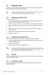
... installed in a chassis). 3. Chapter 1: Product introduction 1-6 1.5 Expansion slots In the future, you may cause you physical injury and damage motherboard components. 1.5.1 Installing an expansion card To install an expansion card: 1. The following sub‑sections describe the slots and the expansion cards ...expansion card, read the documentation that complies with it by adjusting the software settings. 1. Remove the system unit cover (if your motherboard is completely seated on shared slots, ensure that the drivers support "Share IRQ" or that they support. Keep the screw for ...
... installed in a chassis). 3. Chapter 1: Product introduction 1-6 1.5 Expansion slots In the future, you may cause you physical injury and damage motherboard components. 1.5.1 Installing an expansion card To install an expansion card: 1. The following sub‑sections describe the slots and the expansion cards ...expansion card, read the documentation that complies with it by adjusting the software settings. 1. Remove the system unit cover (if your motherboard is completely seated on shared slots, ensure that the drivers support "Share IRQ" or that they support. Keep the screw for ...
User Manual
Page 20
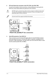
...Serial ATA 3Gb/s is faster than the standard parallel ATA (133 MB/s). P5G41T-M LX2/GB/LPT CHA_FAN Rotation +12V GND CPU_FAN CPU FAN PWM CPU FAN IN CPU FAN PWR GND P5G41T-M LX2/GB/LPT fan connectors 3. GND RSATA_RXN4 RSATA_RXP4 GND RSATA_TXN4 RSATA_TXP4 GND SATA4 GND ...GND RSATA_TXN1 RSATA_TXP1 GND P5G41T-M LX2/GB/LPT SATA2 SATA1 P5G41T-M LX2/GB/LPT SATA connectors 1-11 ASUS P5G41T-M LX2 Series 2. DO NOT forget to connect the fan cables to the fan connectors on the fan connectors! Insufficient air flow inside the system may damage the motherboard components. CPU and ...
...Serial ATA 3Gb/s is faster than the standard parallel ATA (133 MB/s). P5G41T-M LX2/GB/LPT CHA_FAN Rotation +12V GND CPU_FAN CPU FAN PWM CPU FAN IN CPU FAN PWR GND P5G41T-M LX2/GB/LPT fan connectors 3. GND RSATA_RXN4 RSATA_RXP4 GND RSATA_TXN4 RSATA_TXP4 GND SATA4 GND ...GND RSATA_TXN1 RSATA_TXP1 GND P5G41T-M LX2/GB/LPT SATA2 SATA1 P5G41T-M LX2/GB/LPT SATA connectors 1-11 ASUS P5G41T-M LX2 Series 2. DO NOT forget to connect the fan cables to the fan connectors on the fan connectors! Insufficient air flow inside the system may damage the motherboard components. CPU and ...
User Manual
Page 21
... 5. Master Slave Master Slave Cable connector Black Black Gray Black or gray • Pin 20 on the Ultra DMA cable connector. P5G41T-M LX2/GB/LPT IDE connector Single device Two devices Drive jumper setting Cable-Select or Master Cable-Select Master Slave Mode of the following modes to...-1 pin PRI_IDE) The onboard IDE connector is removed to configure your device. 4. There are three connectors on the IDE ribbon cable to the motherboard's IDE connector, then select one of device(s) - Connect the blue connector to PIN 1. Optical drive audio connector (4-pin CD) These connectors ...
... 5. Master Slave Master Slave Cable connector Black Black Gray Black or gray • Pin 20 on the Ultra DMA cable connector. P5G41T-M LX2/GB/LPT IDE connector Single device Two devices Drive jumper setting Cable-Select or Master Cable-Select Master Slave Mode of the following modes to...-1 pin PRI_IDE) The onboard IDE connector is removed to configure your device. 4. There are three connectors on the IDE ribbon cable to the motherboard's IDE connector, then select one of device(s) - Connect the blue connector to PIN 1. Optical drive audio connector (4-pin CD) These connectors ...
User Manual
Page 22
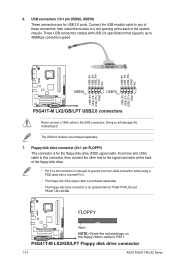
... FLOPPY) This connector is an optional item for P5G41T-M LX2 and P5G41T-M LX2/GB. 6. USB connectors (10-1 pin USB56, USB78) These connectors are for the floppy disk drive (FDD) signal cable. Doing so will damage the motherboard! The USB 2.0 module is removed to prevent ...+ GND NC P5G41T-M LX2/GB/LPT USB56 PIN 1 USB78 PIN 1 USB+5V USB_P7USB_P7+ GND USB+5V USB_P5USB_P5+ GND P5G41T-M LX2/GB/LPT USB2.0 connectors Never connect a 1394 cable to 480Mbps connection speed. P5G41T-M LX2/GB/LPT Floppy disk drive connector 1-13 ASUS P5G41T-M LX2 Series FLOPPY P5G41T-M LX2/GB/LPT PIN 1...
... FLOPPY) This connector is an optional item for P5G41T-M LX2 and P5G41T-M LX2/GB. 6. USB connectors (10-1 pin USB56, USB78) These connectors are for the floppy disk drive (FDD) signal cable. Doing so will damage the motherboard! The USB 2.0 module is removed to prevent ...+ GND NC P5G41T-M LX2/GB/LPT USB56 PIN 1 USB78 PIN 1 USB+5V USB_P7USB_P7+ GND USB+5V USB_P5USB_P5+ GND P5G41T-M LX2/GB/LPT USB2.0 connectors Never connect a 1394 cable to 480Mbps connection speed. P5G41T-M LX2/GB/LPT Floppy disk drive connector 1-13 ASUS P5G41T-M LX2 Series FLOPPY P5G41T-M LX2/GB/LPT PIN 1...
User Manual
Page 23
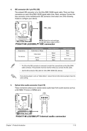
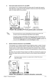
If you want to connect a high-definition front panel audio module to this connector to avail of the motherboard's high-definition audio capability. • If you intend to [AC97]. Chassis intrusion connector (4-1 pin CHASSIS) ...use the chassis intrusion detection feature. See section 2.4.2 Chipset for P5G41T-M LX2 and P5G41T-M LX2/GB. The Chassis intrusion connector is for a chassis-mounted intrusion detection sensor or switch. CHASSIS +5VSB_MB Chassis Signal GND P5G41T-M LX2/GB/LPT P5G41T-M LX2/GB/LPT Chassis intrusion connector Chapter 1: Product introduction 1-14 By default...
If you want to connect a high-definition front panel audio module to this connector to avail of the motherboard's high-definition audio capability. • If you intend to [AC97]. Chassis intrusion connector (4-1 pin CHASSIS) ...use the chassis intrusion detection feature. See section 2.4.2 Chipset for P5G41T-M LX2 and P5G41T-M LX2/GB. The Chassis intrusion connector is for a chassis-mounted intrusion detection sensor or switch. CHASSIS +5VSB_MB Chassis Signal GND P5G41T-M LX2/GB/LPT P5G41T-M LX2/GB/LPT Chassis intrusion connector Chapter 1: Product introduction 1-14 By default...

User Manual
Page 25
... DVD Place the Support DVD to maximize the features of the Support DVD are subject to avail all motherboard features. 1.8 Software support 1.8.1 Installing an operating system This motherboard supports Windows® XP/Vista/7 operating systems (OS). The DVD automatically displays the Drivers menu if ...the file ASSETUP.EXE from the BIN folder. Always install the latest OS version and corresponding updates to the optical drive. Visit the ASUS website at any time without notice. To run the DVD. Chapter 1: Product introduction 1-16 The contents of your OS documentation for...
... DVD Place the Support DVD to maximize the features of the Support DVD are subject to avail all motherboard features. 1.8 Software support 1.8.1 Installing an operating system This motherboard supports Windows® XP/Vista/7 operating systems (OS). The DVD automatically displays the Drivers menu if ...the file ASSETUP.EXE from the BIN folder. Always install the latest OS version and corresponding updates to the optical drive. Visit the ASUS website at any time without notice. To run the DVD. Chapter 1: Product introduction 1-16 The contents of your OS documentation for...
User Manual
Page 26
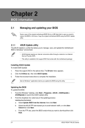
... utility. 2. Select Update BIOS from the Internet a. Select the ASUS FTP site nearest you want to download then click Next. 2-1 ASUS P5G41T-M LX2 Series Installing ASUS Update To install ASUS Update: 1. From the FTP site, select the BIOS version that comes with the motherboard package. Follow the onscreen instructions to avoid network traffic, or click Auto Select...
... utility. 2. Select Update BIOS from the Internet a. Select the ASUS FTP site nearest you want to download then click Next. 2-1 ASUS P5G41T-M LX2 Series Installing ASUS Update To install ASUS Update: 1. From the FTP site, select the BIOS version that comes with the motherboard package. Follow the onscreen instructions to avoid network traffic, or click Auto Select...
User Manual
Page 28
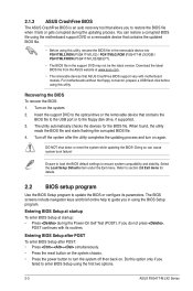
... Self Test (POST). Doing so can restore a corrupted BIOS file using the first two options. 2-3 ASUS P5G41T-M LX2 Series If you do not press , POST continues with motherboard models. Entering BIOS Setup after POST To enter BIOS Setup after the utility completes the updating process and ...in the removable device into PG41TML2.ROM (P5G41T-M LX2) / PG41TMLG.ROM (P5G41T-M LX2/GB) / PG41TMLP.ROM (P5G41T-M LX2/GB/LPT). • The BIOS file in the support DVD may not be the latest version. Entering BIOS Setup at startup To enter BIOS Setup at www.asus.com. • The removable devices that...
... Self Test (POST). Doing so can restore a corrupted BIOS file using the first two options. 2-3 ASUS P5G41T-M LX2 Series If you do not press , POST continues with motherboard models. Entering BIOS Setup after POST To enter BIOS Setup after the utility completes the updating process and ...in the removable device into PG41TML2.ROM (P5G41T-M LX2) / PG41TMLG.ROM (P5G41T-M LX2/GB) / PG41TMLP.ROM (P5G41T-M LX2/GB/LPT). • The BIOS file in the support DVD may not be the latest version. Entering BIOS Setup at startup To enter BIOS Setup at www.asus.com. • The removable devices that...
User Manual
Page 29
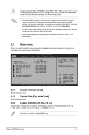
.../xxxx] Sets the system date. 2.3.3 Legacy Diskette A [1.44M, 3.5 in this section are for P5G41T-M LX2/GB/LPT only. See section 2.8 Exit Menu. • The BIOS setup screens shown in .] Sets ... Storage Configuration System Information Use [+] or [-] to your screen. • Visit the ASUS website at www.asus.com to ensure system compatibility and stability. Main Advanced BIOS SETUP UTILITY Power Boot Tools Exit..., load the default settings to download the latest BIOS file for this motherboard apply for this motherboard. 2.3 Main menu When you enter the BIOS Setup program, the Main...
.../xxxx] Sets the system date. 2.3.3 Legacy Diskette A [1.44M, 3.5 in this section are for P5G41T-M LX2/GB/LPT only. See section 2.8 Exit Menu. • The BIOS setup screens shown in .] Sets ... Storage Configuration System Information Use [+] or [-] to your screen. • Visit the ASUS website at www.asus.com to ensure system compatibility and stability. Main Advanced BIOS SETUP UTILITY Power Boot Tools Exit..., load the default settings to download the latest BIOS file for this motherboard apply for this motherboard. 2.3 Main menu When you enter the BIOS Setup program, the Main...

User Manual
Page 37
...186;C/xxxºF] or [Ignored] MB Temperature [xxxºC/xxxºF] or [Ignored] The onboard hardware monitor automatically detects and displays the motherboard and CPU temperatures. Configuration options: [Disabled] [Enabled] Power On By External Modem [Disabled] Enables or disables RI to generate a wake .../2 mouse to generate a wake event. 2.5.4 APM Configuration Restore on AC Power Loss [Power Off] When this item is not connected to the motherboard, the field shows [N/A]. If the fan is set to generate a wake event. Configuration options: [Disabled] [Enabled] Power On by PCI(E)...
...186;C/xxxºF] or [Ignored] MB Temperature [xxxºC/xxxºF] or [Ignored] The onboard hardware monitor automatically detects and displays the motherboard and CPU temperatures. Configuration options: [Disabled] [Enabled] Power On By External Modem [Disabled] Enables or disables RI to generate a wake .../2 mouse to generate a wake event. 2.5.4 APM Configuration Restore on AC Power Loss [Power Off] When this item is not connected to the motherboard, the field shows [N/A]. If the fan is set to generate a wake event. Configuration options: [Disabled] [Enabled] Power On by PCI(E)...


