
User Manual
Page 8
... ports P5G41T-M LX2/GB and P5G41T-M LX2/GB/LPT: Realtek® RTL8112L Gigabit Ethernet PCIe controller P5G41T-M LX2: Realtek® RTL8103EL 10/100Mbps Ethernet PCIe controller VIA® VT1705 High Definition Audio 6-channel CODEC Supports Multi-streaming technology Supports up to 8GB system memory * Refer to www.asus.com for...modules - shared memory of 4GB or more, Windows® 32-bit operating system may only recognize less than 3GB. P5G41T-M LX2 Series specifications summary CPU Chipset Front Side Bus Memory Graphics Expansion slots Storage LAN Audio USB LGA775 socket for Intel®...
... ports P5G41T-M LX2/GB and P5G41T-M LX2/GB/LPT: Realtek® RTL8112L Gigabit Ethernet PCIe controller P5G41T-M LX2: Realtek® RTL8103EL 10/100Mbps Ethernet PCIe controller VIA® VT1705 High Definition Audio 6-channel CODEC Supports Multi-streaming technology Supports up to 8GB system memory * Refer to www.asus.com for...modules - shared memory of 4GB or more, Windows® 32-bit operating system may only recognize less than 3GB. P5G41T-M LX2 Series specifications summary CPU Chipset Front Side Bus Memory Graphics Expansion slots Storage LAN Audio USB LGA775 socket for Intel®...
User Manual
Page 9
... 1 x Chassis fan connector 1 x 24-pin EATX power connector 1 x 4-pin ATX 12V power connector 1 x Chassis intrusion connector (optional for P5G41T-M LX2 and P5G41T-M LX2/GB) 1 x Floppy disk drive connector (optional for P5G41T-M LX2 and P5G41T-M LX2/GB) ASUS CrashFree BIOS 3 ASUS Q-Fan ASUS EZ Flash 2 ASUS MyLogo 2 8Mb Flash ROM, AMI BIOS, PnP, DMI 2.0, WfM 2.0, ACPI 2.0a, SM BIOS 2.5 WOL, PXE, PME Wake up, WOR...
... 1 x Chassis fan connector 1 x 24-pin EATX power connector 1 x 4-pin ATX 12V power connector 1 x Chassis intrusion connector (optional for P5G41T-M LX2 and P5G41T-M LX2/GB) 1 x Floppy disk drive connector (optional for P5G41T-M LX2 and P5G41T-M LX2/GB) ASUS CrashFree BIOS 3 ASUS Q-Fan ASUS EZ Flash 2 ASUS MyLogo 2 8Mb Flash ROM, AMI BIOS, PnP, DMI 2.0, WfM 2.0, ACPI 2.0a, SM BIOS 2.5 WOL, PXE, PME Wake up, WOR...
User Manual
Page 10
... component, place it on them due to static electricity. • Hold components by the edges to page ix for buying an ASUS® P5G41T-M LX2 Series motherboard! Refer to avoid touching the ICs on a grounded antistatic pad or in the bag that came with a standby power... before removing or plugging in soft-off or the power cord is switched off mode. SB_PWR P5G41T-M LX2/GB/LPT ON OFF Standby Power Powered Off P5G41T-M LX2/GB/LPT Onboard power LED 1-1 ASUS P5G41T-M LX2 Series The illustration below shows the location of the items is damaged or missing, contact your ...
... component, place it on them due to static electricity. • Hold components by the edges to page ix for buying an ASUS® P5G41T-M LX2 Series motherboard! Refer to avoid touching the ICs on a grounded antistatic pad or in the bag that came with a standby power... before removing or plugging in soft-off or the power cord is switched off mode. SB_PWR P5G41T-M LX2/GB/LPT ON OFF Standby Power Powered Off P5G41T-M LX2/GB/LPT Onboard power LED 1-1 ASUS P5G41T-M LX2 Series The illustration below shows the location of the items is damaged or missing, contact your ...
User Manual
Page 16
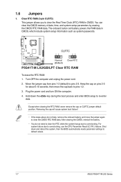
... the onboard battery and move the cap back to default values. 1-7 ASUS P5G41T-M LX2 Series You can clear the CMOS memory of date, time, and system setup parameters by erasing the CMOS RTC RAM data. CLRTC 12 23 P5G41T-M LX2/GB/LPT Normal (Default) Clear RTC P5G41T-M LX2/GB/LPT Clear RTC RAM To erase the RTC RAM: 1. Plug...
... the onboard battery and move the cap back to default values. 1-7 ASUS P5G41T-M LX2 Series You can clear the CMOS memory of date, time, and system setup parameters by erasing the CMOS RTC RAM data. CLRTC 12 23 P5G41T-M LX2/GB/LPT Normal (Default) Clear RTC P5G41T-M LX2/GB/LPT Clear RTC RAM To erase the RTC RAM: 1. Plug...
User Manual
Page 18
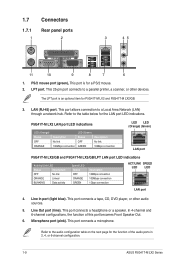
...100Mbps connection LED (Green) Status OFF GREEN Description No link 10Mbps connection LED LED (Orange) (Green) LAN port P5G41T-M LX2/GB and P5G41T-M LX2/GB/LPT LAN port LED indications Activity/Link LED Status Description OFF No link ORANGE Linked BLINKING Data activity Speed LED Status...Speaker Out. 6. LPT port. Refer to the audio configuration table on the next page for P5G41T-M LX2 and P5G41T-M LX2/GB. 3. In 4-channel and 6-channel configurations, the function of the audio ports in 2, 4, or 6-channel configuration. 1-9 ASUS P5G41T-M LX2 Series Microphone port (pink).
...100Mbps connection LED (Green) Status OFF GREEN Description No link 10Mbps connection LED LED (Orange) (Green) LAN port P5G41T-M LX2/GB and P5G41T-M LX2/GB/LPT LAN port LED indications Activity/Link LED Status Description OFF No link ORANGE Linked BLINKING Data activity Speed LED Status...Speaker Out. 6. LPT port. Refer to the audio configuration table on the next page for P5G41T-M LX2 and P5G41T-M LX2/GB. 3. In 4-channel and 6-channel configurations, the function of the audio ports in 2, 4, or 6-channel configuration. 1-9 ASUS P5G41T-M LX2 Series Microphone port (pink).
User Manual
Page 19
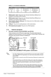
... Standby +5 Volts Power OK -5 Volts PIN 1 GND +5 Volts GND GND GND GND GND GND P5G41T-M LX2/GB/LPT +5 Volts GND PSON# GND +3 Volts -12 Volts +3 Volts +3 Volts PIN 1 P5G41T-M LX2/GB/LPT ATX power connectors • For a fully configured system, we recommend that complies with more power... or later version and provides a minimum power of 400W. • DO NOT forget to the Recommended Power Supply Wattage Calculator at http://support.asus. PS/2 keyboard port (purple). Video Graphics Adapter (VGA) port. This port is for connecting USB 2.0 devices. 8. USB 2.0 ports 3...
... Standby +5 Volts Power OK -5 Volts PIN 1 GND +5 Volts GND GND GND GND GND GND P5G41T-M LX2/GB/LPT +5 Volts GND PSON# GND +3 Volts -12 Volts +3 Volts +3 Volts PIN 1 P5G41T-M LX2/GB/LPT ATX power connectors • For a fully configured system, we recommend that complies with more power... or later version and provides a minimum power of 400W. • DO NOT forget to the Recommended Power Supply Wattage Calculator at http://support.asus. PS/2 keyboard port (purple). Video Graphics Adapter (VGA) port. This port is for connecting USB 2.0 devices. 8. USB 2.0 ports 3...
User Manual
Page 20
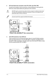
... GND RSATA_RXN3 RSATA_RXP3 GND RSATA_TXN3 RSATA_TXP3 GND SATA3 GND RSATA_RXN2 RSATA_RXP2 GND RSATA_TXN2 RSATA_TXP2 GND GND RSATA_RXN1 RSATA_RXP1 GND RSATA_TXN1 RSATA_TXP1 GND P5G41T-M LX2/GB/LPT SATA2 SATA1 P5G41T-M LX2/GB/LPT SATA connectors 1-11 ASUS P5G41T-M LX2 Series DO NOT forget to connect the fan cables to the fan connectors on the fan connectors! Do not place jumper...
... GND RSATA_RXN3 RSATA_RXP3 GND RSATA_TXN3 RSATA_TXP3 GND SATA3 GND RSATA_RXN2 RSATA_RXP2 GND RSATA_TXN2 RSATA_TXP2 GND GND RSATA_RXN1 RSATA_RXP1 GND RSATA_TXN1 RSATA_TXP1 GND P5G41T-M LX2/GB/LPT SATA2 SATA1 P5G41T-M LX2/GB/LPT SATA connectors 1-11 ASUS P5G41T-M LX2 Series DO NOT forget to connect the fan cables to the fan connectors on the fan connectors! Do not place jumper...
User Manual
Page 22
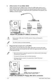
..., USB78) These connectors are for P5G41T-M LX2 and P5G41T-M LX2/GB. P5G41T-M LX2/GB/LPT Floppy disk drive connector 1-13 ASUS P5G41T-M LX2 Series USB+5V USB_P8USB_P8+ GND NC USB+5V USB_P6USB_P6+ GND NC P5G41T-M LX2/GB/LPT USB56 PIN 1 USB78 PIN 1 USB+5V USB_P7USB_P7+ GND USB+5V USB_P5USB_P5+ GND P5G41T-M LX2/GB/LPT USB2.0 connectors Never connect a... the USB module cable to any of these connectors, then install the module to the USB connectors. FLOPPY P5G41T-M LX2/GB/LPT PIN 1 NOTE: Orient the red markings on the connector is an optional item for USB 2.0 ports. Doing ...
..., USB78) These connectors are for P5G41T-M LX2 and P5G41T-M LX2/GB. P5G41T-M LX2/GB/LPT Floppy disk drive connector 1-13 ASUS P5G41T-M LX2 Series USB+5V USB_P8USB_P8+ GND NC USB+5V USB_P6USB_P6+ GND NC P5G41T-M LX2/GB/LPT USB56 PIN 1 USB78 PIN 1 USB+5V USB_P7USB_P7+ GND USB+5V USB_P5USB_P5+ GND P5G41T-M LX2/GB/LPT USB2.0 connectors Never connect a... the USB module cable to any of these connectors, then install the module to the USB connectors. FLOPPY P5G41T-M LX2/GB/LPT PIN 1 NOTE: Orient the red markings on the connector is an optional item for USB 2.0 ports. Doing ...
User Manual
Page 24
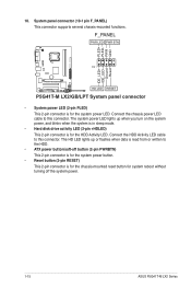
... (2-pin +HDLED) This 2-pin connector is for the chassis-mounted reset button for the system power LED. F_PANEL PWR LED PWR BTN PIN 1 P5G41T-M LX2/GB/LPT HD LED RESET P5G41T-M LX2/GB/LPT System panel connector • System power LED (2-pin PLED) This 2-pin connector is for system reboot without turning off button (2-pin PWRBTN... LED lights up or flashes when data is read from or written to the HDD. • ATX power button/soft-off the system power. 1-15 ASUS P5G41T-M LX2 Series Connect the HDD Activity LED cable to this connector.
... (2-pin +HDLED) This 2-pin connector is for the chassis-mounted reset button for the system power LED. F_PANEL PWR LED PWR BTN PIN 1 P5G41T-M LX2/GB/LPT HD LED RESET P5G41T-M LX2/GB/LPT System panel connector • System power LED (2-pin PLED) This 2-pin connector is for system reboot without turning off button (2-pin PWRBTN... LED lights up or flashes when data is read from or written to the HDD. • ATX power button/soft-off the system power. 1-15 ASUS P5G41T-M LX2 Series Connect the HDD Activity LED cable to this connector.
User Manual
Page 27
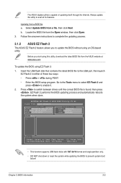
...Flash 2: 1. Updating from the Open window, then click Open. 3. ASUSTek EZ Flash 2 BIOS ROM Utility V3.44 FLASH TYPE: MXIC 25L8005 Current ROM BOARD:P5G41T-M LX2/GB/LPT VER:0305 (H:00 B:00) DATE: 10/29/2009 Update ROM BOARD: Unknown VER: Unknown DATE: Unknown PATH: A:\ A: Note [Enter] Select or...the system when done. Before you to the USB port, then launch EZ Flash 2 in either of updating itself through the Internet. The ASUS Update utility is found, then press . To update the BIOS using an OS‑based utility. Chapter 2: BIOS information 2-2 Always update the...
...Flash 2: 1. Updating from the Open window, then click Open. 3. ASUSTek EZ Flash 2 BIOS ROM Utility V3.44 FLASH TYPE: MXIC 25L8005 Current ROM BOARD:P5G41T-M LX2/GB/LPT VER:0305 (H:00 B:00) DATE: 10/29/2009 Update ROM BOARD: Unknown VER: Unknown DATE: Unknown PATH: A:\ A: Note [Enter] Select or...the system when done. Before you to the USB port, then launch EZ Flash 2 in either of updating itself through the Internet. The ASUS Update utility is found, then press . To update the BIOS using an OS‑based utility. Chapter 2: BIOS information 2-2 Always update the...
User Manual
Page 28
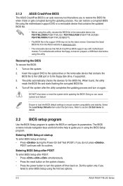
... BIOS Setup at startup To enter BIOS Setup at www.asus.com. • The removable devices that contains the updated BIOS file. • Before using this utility, rename the BIOS file in the removable device into PG41TML2.ROM (P5G41T-M LX2) / PG41TMLG.ROM (P5G41T-M LX2/GB) / PG41TMLP.ROM (P5G41T-M LX2/GB/LPT). • The BIOS file in using this option...
... BIOS Setup at startup To enter BIOS Setup at www.asus.com. • The removable devices that contains the updated BIOS file. • Before using this utility, rename the BIOS file in the removable device into PG41TML2.ROM (P5G41T-M LX2) / PG41TMLG.ROM (P5G41T-M LX2/GB) / PG41TMLP.ROM (P5G41T-M LX2/GB/LPT). • The BIOS file in using this option...
User Manual
Page 29
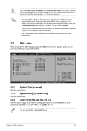
... the power button, reset button, or the ++ keys to force reset from the operating system. • The default BIOS settings for this motherboard apply for P5G41T-M LX2/GB/LPT only. Primary IDE Master Primary IDE Slave SATA 1 SATA 2 SATA 3 SATA 4 :[Not Detected] :[Not Detected] :[Not Detected] :[Not Detected] :[...recommend to always shut down the system properly from a running operating system can cause damage to your screen. • Visit the ASUS website at www.asus.com to download the latest BIOS file for this motherboard. 2.3 Main menu When you enter the BIOS Setup program, the Main...
... the power button, reset button, or the ++ keys to force reset from the operating system. • The default BIOS settings for this motherboard apply for P5G41T-M LX2/GB/LPT only. Primary IDE Master Primary IDE Slave SATA 1 SATA 2 SATA 3 SATA 4 :[Not Detected] :[Not Detected] :[Not Detected] :[Not Detected] :[...recommend to always shut down the system properly from a running operating system can cause damage to your screen. • Visit the ASUS website at www.asus.com to download the latest BIOS file for this motherboard. 2.3 Main menu When you enter the BIOS Setup program, the Main...

User Manual
Page 34
... address. Configuration options: [Normal] The following item is for P5G41T-M LX2/GB/LPT with an LPT port at the back panel. Configuration options: [Disabled] [3F8/IRQ4] [2F8/IRQ3] [3E8/IRQ4] [2E8/IRQ3] The following item is for Serial Port1. Configuration options: [IRQ5] [IRQ7] 2-9 ASUS P5G41T-M LX2 Series 2.4.3 Onboard Devices Configuration Serial Port1 Address [3F8/IRQ4] Allows...
... address. Configuration options: [Normal] The following item is for P5G41T-M LX2/GB/LPT with an LPT port at the back panel. Configuration options: [Disabled] [3F8/IRQ4] [2F8/IRQ3] [3E8/IRQ4] [2E8/IRQ3] The following item is for Serial Port1. Configuration options: [IRQ5] [IRQ7] 2-9 ASUS P5G41T-M LX2 Series 2.4.3 Onboard Devices Configuration Serial Port1 Address [3F8/IRQ4] Allows...


