

User Manual
Page 3
... Notices...v Safety information vi About this guide vi P5G41-M LX2 Series specifications summary viii Chapter 1: Product introduction 1.1 Before you proceed 1-1 1.2 Motherboard overview 1-2 1.2.1 Motherboard layout 1-2 1.2.2 Layout contents 1-2 1.3 Central Processing Unit (CPU 1-3 1.4 System memory 1-3 1.4.1 Overview 1-3 1.4.2 Memory configurations 1-4 1.5 Expansion slots 1-7 1.5.1 Installing an... Chapter 2: BIOS information 2.1 Managing and updating your BIOS 2-1 2.1.1 ASUS Update utility 2-1 2.1.2 ASUS EZ Flash 2 2-2 2.1.3 ASUS CrashFree BIOS 2-3 2.2 BIOS setup program 2-3 iii
... Notices...v Safety information vi About this guide vi P5G41-M LX2 Series specifications summary viii Chapter 1: Product introduction 1.1 Before you proceed 1-1 1.2 Motherboard overview 1-2 1.2.1 Motherboard layout 1-2 1.2.2 Layout contents 1-2 1.3 Central Processing Unit (CPU 1-3 1.4 System memory 1-3 1.4.1 Overview 1-3 1.4.2 Memory configurations 1-4 1.5 Expansion slots 1-7 1.5.1 Installing an... Chapter 2: BIOS information 2.1 Managing and updating your BIOS 2-1 2.1.1 ASUS Update utility 2-1 2.1.2 ASUS EZ Flash 2 2-2 2.1.3 ASUS CrashFree BIOS 2-3 2.2 BIOS setup program 2-3 iii
User Manual
Page 8
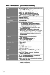
... connector 4 x Serial ATA 3Gb/s ports P5G41-M LX2/GB: Realtek® RTL8112L Gigabit Ethernet PCIe controller P5G41-M LX2: Realtek® RTL8103EL 10/100Mbps Ethernet PCIe controller VIA® VT1705 High Definition Audio 6-channel CODEC Supports Multi-streaming technology Supports up to 8GB system memory * Refer to www.asus.com for the latest Memory QVL (Qualified Vendors Lists). ** When you...
... connector 4 x Serial ATA 3Gb/s ports P5G41-M LX2/GB: Realtek® RTL8112L Gigabit Ethernet PCIe controller P5G41-M LX2: Realtek® RTL8103EL 10/100Mbps Ethernet PCIe controller VIA® VT1705 High Definition Audio 6-channel CODEC Supports Multi-streaming technology Supports up to 8GB system memory * Refer to www.asus.com for the latest Memory QVL (Qualified Vendors Lists). ** When you...
User Manual
Page 12
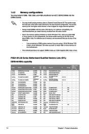
...Memory Modules (DIMM) sockets. ASUS will shoulder the cost of repair only if the damage is missing, or if you see any damage to the socket contacts resulting from incorrect CPU installation/removal, or misplacement/loss/incorrect removal of the DDR2 DIMM sockets: DIMM_A1 DIMM_B1 P5G41-M LX2/GB Channel Channel A Channel B Sockets DIMM_A1 DIMM_B1 P5G41-M LX2/GB... 240-pin DDR2 DIMM sockets ASUS P5G41-M LX2 Series 1-3
...Memory Modules (DIMM) sockets. ASUS will shoulder the cost of repair only if the damage is missing, or if you see any damage to the socket contacts resulting from incorrect CPU installation/removal, or misplacement/loss/incorrect removal of the DDR2 DIMM sockets: DIMM_A1 DIMM_B1 P5G41-M LX2/GB Channel Channel A Channel B Sockets DIMM_A1 DIMM_B1 P5G41-M LX2/GB... 240-pin DDR2 DIMM sockets ASUS P5G41-M LX2 Series 1-3
User Manual
Page 13
...8151030036559 5-5-5-15 - GEIL - 5 - PSC A3R1GE3CFF734MAA0J 5 - PSC A3R1GE3CFF733MAA00 5 - Transced TQ243PCF8T0834 5 - PSC A3R12E3GEF633ACAOY 5 - 1.4.2 Memory configurations You may install 512MB, 1GB, 2GB, and 4GB unbuffered non‑ECC DDR2 DIMMs into the DIMM sockets. • You may...introduction Use a maximum of 3GB system memory if you do any of 256 megabits (Mb) chips or less. Elpida E1108AFSE-8E-F 5 1.8V Elpida E5108AJBG-6E-E 5 1.8V Elpida E1108AFBG-8E-F 5 1.8V Micron D9HNL 7ZE17 5 - P5G41-M LX2 Series Motherboard Qualified Vendors Lists (QVL)...
...8151030036559 5-5-5-15 - GEIL - 5 - PSC A3R1GE3CFF734MAA0J 5 - PSC A3R1GE3CFF733MAA00 5 - Transced TQ243PCF8T0834 5 - PSC A3R12E3GEF633ACAOY 5 - 1.4.2 Memory configurations You may install 512MB, 1GB, 2GB, and 4GB unbuffered non‑ECC DDR2 DIMMs into the DIMM sockets. • You may...introduction Use a maximum of 3GB system memory if you do any of 256 megabits (Mb) chips or less. Elpida E1108AFSE-8E-F 5 1.8V Elpida E5108AJBG-6E-E 5 1.8V Elpida E1108AFBG-8E-F 5 1.8V Micron D9HNL 7ZE17 5 - P5G41-M LX2 Series Motherboard Qualified Vendors Lists (QVL)...

User Manual
Page 15
... Super Talent - 4 1.8V ELPIDA E1108ACBG-8E-E 5 - Transcend TQ123YBF8 T0747 5 - Transced TQ243PCF8 5 - Visit the ASUS website at www.asus.com for the latest QVL. 1-6 Chapter 1: Product introduction PSC XCP271A3G-A 5 - Samsung K4T1G084QE - - V-Data VD29608A8A-25EG20813... SS/ DS 1024MB DS 1024MB DS 2048MB(Kit of 2) DS 2048MB DS 4096MB(Kit of 2) DS 4096MB(Kit of dual-channel memory configuration. Transced TQ123PJF8F0801 5 - Samsung K4T51083QG-HCF7 6 - Micron 7HD22 D9GMH 5 - Mircon 7HD22D9GMH 5 - Samsung K4T51083QG - - CL...
... Super Talent - 4 1.8V ELPIDA E1108ACBG-8E-E 5 - Transcend TQ123YBF8 T0747 5 - Transced TQ243PCF8 5 - Visit the ASUS website at www.asus.com for the latest QVL. 1-6 Chapter 1: Product introduction PSC XCP271A3G-A 5 - Samsung K4T1G084QE - - V-Data VD29608A8A-25EG20813... SS/ DS 1024MB DS 1024MB DS 2048MB(Kit of 2) DS 2048MB DS 4096MB(Kit of 2) DS 4096MB(Kit of dual-channel memory configuration. Transced TQ123PJF8F0801 5 - Samsung K4T51083QG-HCF7 6 - Micron 7HD22 D9GMH 5 - Mircon 7HD22D9GMH 5 - Samsung K4T51083QG - - CL...
User Manual
Page 17
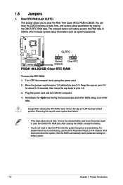
...the RAM data in CMOS. Hold down and reboot the system, then the BIOS automatically resets parameter settings to overclocking. You can clear the CMOS memory of date, time, and system setup parameters by erasing the CMOS RTC RAM data. Keep the cap on CLRTC jumper default position. 1.6 Jumpers... RAM, never remove the cap on pins 2-3 for about 5-10 seconds, then move the jumper again to pins 2-3. CLRTC 12 23 P5G41-M LX2/GB Normal (Default) Clear RTC P5G41-M LX2/GB Clear RTC RAM To erase the RTC RAM: 1. Move the jumper cap from pins 1-2 (default) to clear the CMOS RTC RAM data...
...the RAM data in CMOS. Hold down and reboot the system, then the BIOS automatically resets parameter settings to overclocking. You can clear the CMOS memory of date, time, and system setup parameters by erasing the CMOS RTC RAM data. Keep the cap on CLRTC jumper default position. 1.6 Jumpers... RAM, never remove the cap on pins 2-3 for about 5-10 seconds, then move the jumper again to pins 2-3. CLRTC 12 23 P5G41-M LX2/GB Normal (Default) Clear RTC P5G41-M LX2/GB Clear RTC RAM To erase the RTC RAM: 1. Move the jumper cap from pins 1-2 (default) to clear the CMOS RTC RAM data...
User Manual
Page 32
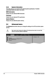
Processor Displays the auto-detected CPU specification. BIOS Information Displays the auto-detected BIOS information. System Memory Displays the auto-detected system memory. 2.4 Advanced menu The Advanced menu items allow you an overview of the Advanced menu items. Incorrect field values can cause the system to change the ...
Processor Displays the auto-detected CPU specification. BIOS Information Displays the auto-detected BIOS information. System Memory Displays the auto-detected system memory. 2.4 Advanced menu The Advanced menu items allow you an overview of the Advanced menu items. Incorrect field values can cause the system to change the ...
User Manual
Page 34
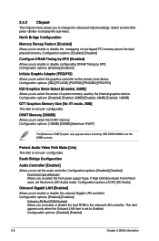
...onboard Gigabit LAN controller. 2.4.2 Chipset The Chipset menu allows you to select the DVMT memory. Configuration options: [Disabled] [Enabled, 32MB] [Enabled, 64MB] [Enabled, 128MB] GTT Graphics Memory Size [No VT mode, 2MB] This item is not user- Configuration options: ...] Allows you to enable or disable the remapping of system memory used , set the audio controller. configurable. configurable. Configuration options: [Disabled] [Enabled] 2-8 Chapter 2: BIOS information North Bridge Configuration Memory Remap Feature [Enabled] Allows you to enable or disable configurating...
...onboard Gigabit LAN controller. 2.4.2 Chipset The Chipset menu allows you to select the DVMT memory. Configuration options: [Disabled] [Enabled, 32MB] [Enabled, 64MB] [Enabled, 128MB] GTT Graphics Memory Size [No VT mode, 2MB] This item is not user- Configuration options: ...] Allows you to enable or disable the remapping of system memory used , set the audio controller. configurable. configurable. Configuration options: [Disabled] [Enabled] 2-8 Chapter 2: BIOS information North Bridge Configuration Memory Remap Feature [Enabled] Allows you to enable or disable configurating...

User Manual
Page 36
...] [Enabled] 2-10 Chapter 2: BIOS information The menu includes setting IRQ and DMA channel resources for either PCI/PnP or legacy ISA devices, and setting the memory size block for Advanced Configuration and Power Interface (ACPI) 2.0 specifications. Take caution when changing the settings of the PCI PnP menu items. Incorrect field values...
...] [Enabled] 2-10 Chapter 2: BIOS information The menu includes setting IRQ and DMA channel resources for either PCI/PnP or legacy ISA devices, and setting the memory size block for Advanced Configuration and Power Interface (ACPI) 2.0 specifications. Take caution when changing the settings of the PCI PnP menu items. Incorrect field values...


