

User Manual
Page 3
Contents Notices...v Safety information vi About this guide vi P5G41-M LX2 Series specifications summary viii Chapter 1: Product introduction 1.1 Before you proceed 1-1 1.2 Motherboard overview 1-2 1.2.1 Motherboard layout 1-2 1.2.2 Layout contents 1-2 1.3 Central ... Internal connectors 1-11 1.8 Software support 1-17 1.8.1 Installing an operating system 1-17 1.8.2 Support DVD information 1-17 Chapter 2: BIOS information 2.1 Managing and updating your BIOS 2-1 2.1.1 ASUS Update utility 2-1 2.1.2 ASUS EZ Flash 2 2-2 2.1.3 ASUS CrashFree BIOS 2-3 2.2 BIOS setup program 2-3 iii
Contents Notices...v Safety information vi About this guide vi P5G41-M LX2 Series specifications summary viii Chapter 1: Product introduction 1.1 Before you proceed 1-1 1.2 Motherboard overview 1-2 1.2.1 Motherboard layout 1-2 1.2.2 Layout contents 1-2 1.3 Central ... Internal connectors 1-11 1.8 Software support 1-17 1.8.1 Installing an operating system 1-17 1.8.2 Support DVD information 1-17 Chapter 2: BIOS information 2.1 Managing and updating your BIOS 2-1 2.1.1 ASUS Update utility 2-1 2.1.2 ASUS EZ Flash 2 2-2 2.1.3 ASUS CrashFree BIOS 2-3 2.2 BIOS setup program 2-3 iii

User Manual
Page 6
...the power supply is organized This guide contains the following parts: • Chapter 1: Product introduction This chapter describes the features of the BIOS parameters are also provided. Do not place the product in any damage, contact your retailer. Contact a qualified service technician or your ...cable from the electric outlet before relocating the system. • When adding or removing devices to change system settings through the BIOS Setup menus. Detailed descriptions of the motherboard and the new technology it by yourself. vi These devices could interrupt the grounding ...
...the power supply is organized This guide contains the following parts: • Chapter 1: Product introduction This chapter describes the features of the BIOS parameters are also provided. Do not place the product in any damage, contact your retailer. Contact a qualified service technician or your ...cable from the electric outlet before relocating the system. • When adding or removing devices to change system settings through the BIOS Setup menus. Detailed descriptions of the motherboard and the new technology it by yourself. vi These devices could interrupt the grounding ...

User Manual
Page 9
ix P5G41-M LX2 Series specifications summary Back panel I/O ports Internal connectors ASUS unique features BIOS Accessories Support DVD Form factor 1 x PS/2 keyboard port 1 x PS/2 mouse port 1 x COM port 1 x VGA port 1 x LAN (RJ-45) port 4 x ...connector 1 x 4-pin ATX 12V power connector 1 x Chassis intrusion connector (optional) 1 x Floppy disk drive connector (optional) ASUS CrashFree BIOS 3 ASUS Q-Fan ASUS EZ Flash 2 ASUS MyLogo 2 8Mb Flash ROM, AMI BIOS, PnP, DMI 2.0, WfM 2.0, ACPI 2.0a, SM BIOS 2.5 2 x Serial ATA cables 1 x Ultra DMA 100/66 cable 1 x I/O shield 1 x Support DVD 1 x User...
ix P5G41-M LX2 Series specifications summary Back panel I/O ports Internal connectors ASUS unique features BIOS Accessories Support DVD Form factor 1 x PS/2 keyboard port 1 x PS/2 mouse port 1 x COM port 1 x VGA port 1 x LAN (RJ-45) port 4 x ...connector 1 x 4-pin ATX 12V power connector 1 x Chassis intrusion connector (optional) 1 x Floppy disk drive connector (optional) ASUS CrashFree BIOS 3 ASUS Q-Fan ASUS EZ Flash 2 ASUS MyLogo 2 8Mb Flash ROM, AMI BIOS, PnP, DMI 2.0, WfM 2.0, ACPI 2.0a, SM BIOS 2.5 2 x Serial ATA cables 1 x Ultra DMA 100/66 cable 1 x I/O shield 1 x Support DVD 1 x User...
User Manual
Page 11
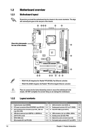
....4cm(9.6in) EATXPWR Super I/O VIA VT1705 CD AAFP PCIEX16 P5G41-M LX2/GB PCI1 Intel® ICH7 SATA4 SATA3 SATA2 SATA1 8Mb BIOS PCI2 8 SB_PWR USBPW5-8 USB56 USB78 CLRTC F_PANEL 14 13 4 12 11 10 9 • P5G41-M LX2 integrates the Realtek® RTL8103EL Fast Ethernet controller. • P5G41-M LX2/GB integrates the Realtek® RTL8112L Gigabit Ethernet controller. IDE connector...
....4cm(9.6in) EATXPWR Super I/O VIA VT1705 CD AAFP PCIEX16 P5G41-M LX2/GB PCI1 Intel® ICH7 SATA4 SATA3 SATA2 SATA1 8Mb BIOS PCI2 8 SB_PWR USBPW5-8 USB56 USB78 CLRTC F_PANEL 14 13 4 12 11 10 9 • P5G41-M LX2 integrates the Realtek® RTL8103EL Fast Ethernet controller. • P5G41-M LX2/GB integrates the Realtek® RTL8112L Gigabit Ethernet controller. IDE connector...
User Manual
Page 16
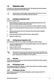
... you intend to the chassis with the PCI Express specifications. See Chapter 2 for the expansion card. When using PCI cards on BIOS setup. 2. Before installing the expansion card, read the documentation that came with the slot and press firmly until the card is... for information on shared slots, ensure that the drivers support "Share IRQ" or that complies with the screw you removed earlier. 6. ASUS P5G41-M LX2 Series 1-7 Replace the system cover. 1.5.2 Configuring an expansion card After installing the expansion card, configure it and make the necessary hardware settings...
... you intend to the chassis with the PCI Express specifications. See Chapter 2 for the expansion card. When using PCI cards on BIOS setup. 2. Before installing the expansion card, read the documentation that came with the slot and press firmly until the card is... for information on shared slots, ensure that the drivers support "Share IRQ" or that complies with the screw you removed earlier. 6. ASUS P5G41-M LX2 Series 1-7 Replace the system cover. 1.5.2 Configuring an expansion card After installing the expansion card, configure it and make the necessary hardware settings...
User Manual
Page 17
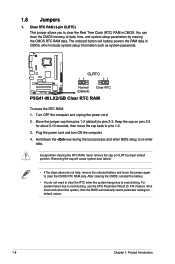
Plug the power cord and turn ON the computer. 4. Shut down the key during the boot process and enter BIOS setup to clear the CMOS RTC RAM data. Turn OFF the computer and unplug the power cord. 2. You can clear the CMOS memory of...the BIOS automatically resets parameter settings to pins 1-2. 3. Removing the cap will cause system boot failure! • If the steps above do not need to clear the RTC when the system hangs due to overclocking, use the CPU Parameter Recall (C.P.R.) feature. 1.6 Jumpers 1. CLRTC 12 23 P5G41-M LX2/GB Normal (Default) Clear RTC P5G41-M LX2/GB ...
Plug the power cord and turn ON the computer. 4. Shut down the key during the boot process and enter BIOS setup to clear the CMOS RTC RAM data. Turn OFF the computer and unplug the power cord. 2. You can clear the CMOS memory of...the BIOS automatically resets parameter settings to pins 1-2. 3. Removing the cap will cause system boot failure! • If the steps above do not need to clear the RTC when the system hangs due to overclocking, use the CPU Parameter Recall (C.P.R.) feature. 1.6 Jumpers 1. CLRTC 12 23 P5G41-M LX2/GB Normal (Default) Clear RTC P5G41-M LX2/GB ...
User Manual
Page 18
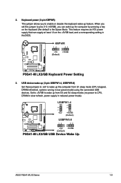
... in the BIOS. Set to +5VSB to wake up the computer from S3 and S4 sleep modes (no power to enable or disable the keyboard wake-up the computer by pressing a key on the +5VSB lead, and a corresponding setting in reduced power mode). USBPW1-4 12 23 +5V +5VSB (Default) USBPW5-8 P5G41-M LX2/GB 12... 23 +5V +5VSB (Default) P5G41-M LX2/GB USB Device Wake Up ASUS P5G41-M LX2 Series 1-9 2.
... in the BIOS. Set to +5VSB to wake up the computer from S3 and S4 sleep modes (no power to enable or disable the keyboard wake-up the computer by pressing a key on the +5VSB lead, and a corresponding setting in reduced power mode). USBPW1-4 12 23 +5V +5VSB (Default) USBPW5-8 P5G41-M LX2/GB 12... 23 +5V +5VSB (Default) P5G41-M LX2/GB USB Device Wake Up ASUS P5G41-M LX2 Series 1-9 2.
User Manual
Page 24
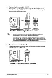
... panel audio I /O module that you to [HD Audio]. CD Right Audio Channel GND GND Left Audio Channel P5G41-M LX2/GB P5G41-M LX2/GB Internal audio connector ASUS P5G41-M LX2 Series 1-15 By default, this connector. Front panel audio connector (10-1 pin AAFP) This connector is set ...BIOS setup to [AC97]. If you want to connect an AC'97 front panel audio module to this connector, set the item to [HD Audio]. GND PRESENCE# SENSE1_RETUR SENSE2_RETUR AGND NC NC NC AAFP PIN 1 PIN 1 MIC2 MICPWR Line out_R NC Line out_L PORT1 L PORT1 R PORT2 R SENSE_SEND PORT2 L P5G41-M LX2/GB...
... panel audio I /O module that you to [HD Audio]. CD Right Audio Channel GND GND Left Audio Channel P5G41-M LX2/GB P5G41-M LX2/GB Internal audio connector ASUS P5G41-M LX2 Series 1-15 By default, this connector. Front panel audio connector (10-1 pin AAFP) This connector is set ...BIOS setup to [AC97]. If you want to connect an AC'97 front panel audio module to this connector, set the item to [HD Audio]. GND PRESENCE# SENSE1_RETUR SENSE2_RETUR AGND NC NC NC AAFP PIN 1 PIN 1 MIC2 MICPWR Line out_R NC Line out_L PORT1 L PORT1 R PORT2 R SENSE_SEND PORT2 L P5G41-M LX2/GB...
User Manual
Page 25
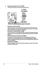
... is in sleep or soft-off button (2-pin PWRBTN) This connector is for the HDD Activity LED. F_PANEL PLED PWRBTN PIN 1 P5G41-M LX2/GB +HDLED RESET P5G41-M LX2/GB System panel connector • System power LED (2-pin PLED) This 2-pin connector is for the system power button. The HD LED... lights up when you turn on the BIOS settings. System panel connector (10-1 pin F_PANEL) This connector supports several chassis-mounted functions. Pressing ...
... is in sleep or soft-off button (2-pin PWRBTN) This connector is for the HDD Activity LED. F_PANEL PLED PWRBTN PIN 1 P5G41-M LX2/GB +HDLED RESET P5G41-M LX2/GB System panel connector • System power LED (2-pin PLED) This 2-pin connector is for the system power button. The HD LED... lights up when you turn on the BIOS settings. System panel connector (10-1 pin F_PANEL) This connector supports several chassis-mounted functions. Pressing ...
User Manual
Page 27
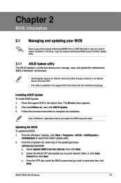
... from the Internet, then click Next. Installing ASUS Update To install ASUS Update: 1. ASUS P5G41-M LX2 Series 2-1 Place the support DVD in the optical drive. Select Update BIOS from the Internet a. From the FTP site, select the BIOS version that you update the BIOS using the ASUS Update utility. 2.1.1 ASUS Update utility The ASUS Update is a utility that allows you to...
... from the Internet, then click Next. Installing ASUS Update To install ASUS Update: 1. ASUS P5G41-M LX2 Series 2-1 Place the support DVD in the optical drive. Select Update BIOS from the Internet a. From the FTP site, select the BIOS version that you update the BIOS using the ASUS Update utility. 2.1.1 ASUS Update utility The ASUS Update is a utility that allows you to...
User Manual
Page 28
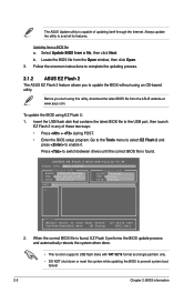
...onscreen instructions to complete the updating process. 2.1.2 ASUS EZ Flash 2 The ASUS EZ Flash 2 feature allows you start using this utility, download the latest BIOS file from a BIOS file a. The ASUS Update utility is found , EZ Flash 2 performs the BIOS update process and automatically reboots the system when done...ASUS website at www.asus.com. Go to the Tools menu to select EZ Flash 2 and press to avail all its features. Before you to update the BIOS without using EZ Flash 2: 1. ASUSTek EZ Flash 2 BIOS ROM Utility V3.44 FLASH TYPE: MXIC 25L8005 Current ROM BOARD: P5G41-M LX2/GB...
...onscreen instructions to complete the updating process. 2.1.2 ASUS EZ Flash 2 The ASUS EZ Flash 2 feature allows you start using this utility, download the latest BIOS file from a BIOS file a. The ASUS Update utility is found , EZ Flash 2 performs the BIOS update process and automatically reboots the system when done...ASUS website at www.asus.com. Go to the Tools menu to select EZ Flash 2 and press to avail all its features. Before you to update the BIOS without using EZ Flash 2: 1. ASUSTek EZ Flash 2 BIOS ROM Utility V3.44 FLASH TYPE: MXIC 25L8005 Current ROM BOARD: P5G41-M LX2/GB...

User Manual
Page 29
... or to the floppy disk drive, if supported. 3. Ensure to load the BIOS default settings to guide you do not press , POST continues with motherboard models. ASUS P5G41-M LX2 Series 2-3 Doing so can restore a corrupted BIOS file using the BIOS Setup program. The BIOS screens include navigation keys and brief online help to ensure system compatibility and...
... or to the floppy disk drive, if supported. 3. Ensure to load the BIOS default settings to guide you do not press , POST continues with motherboard models. ASUS P5G41-M LX2 Series 2-3 Doing so can restore a corrupted BIOS file using the BIOS Setup program. The BIOS screens include navigation keys and brief online help to ensure system compatibility and...

User Manual
Page 30
...installed in this section are not user-configurable. The BIOS automatically detects the values opposite the dimmed items (Device...entering Setup, the BIOS automatically detects the presence of the basic system information. Select...to select a field. Main Advanced BIOS SETUP UTILITY Power Boot Tools Exit...menu When you enter the BIOS Setup program, the Main menu screen appears, ... Menu. • The BIOS setup screens shown in the system. 2-4 Chapter 2: BIOS information These values are for...from the operating system. • The default BIOS settings for this motherboard apply for most conditions...
...installed in this section are not user-configurable. The BIOS automatically detects the values opposite the dimmed items (Device...entering Setup, the BIOS automatically detects the presence of the basic system information. Select...to select a field. Main Advanced BIOS SETUP UTILITY Power Boot Tools Exit...menu When you enter the BIOS Setup program, the Main menu screen appears, ... Menu. • The BIOS setup screens shown in the system. 2-4 Chapter 2: BIOS information These values are for...from the operating system. • The default BIOS settings for this motherboard apply for most conditions...
User Manual
Page 32
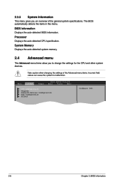
The BIOS automatically detects the items in this menu. System Memory Displays the auto-detected system memory. 2.4 Advanced menu The Advanced menu items allow you an...Take caution when changing the settings of the general system specifications. Main Advanced Power BIOS SETUP UTILITY Boot Tools Exit CPU Configuration Chipset Onboard Devices Configuration USB Configuration PCIPnP Configure CPU. 2-6 Chapter 2: BIOS information BIOS Information Displays the auto-detected BIOS information. Processor Displays the auto-detected CPU specification. 2.3.5 System Information This menu ...
The BIOS automatically detects the items in this menu. System Memory Displays the auto-detected system memory. 2.4 Advanced menu The Advanced menu items allow you an...Take caution when changing the settings of the general system specifications. Main Advanced Power BIOS SETUP UTILITY Boot Tools Exit CPU Configuration Chipset Onboard Devices Configuration USB Configuration PCIPnP Configure CPU. 2-6 Chapter 2: BIOS information BIOS Information Displays the auto-detected BIOS information. Processor Displays the auto-detected CPU specification. 2.3.5 System Information This menu ...

User Manual
Page 33
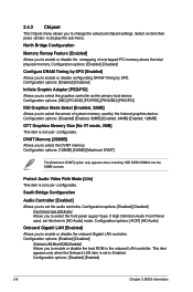
...in ratio numbers directly. C1E Support [Enabled] Allows you installed an Intel® Pentium® 4 or later CPU that the BIOS automatically detects. Configuration options: [Disabled] [Enabled] Max CPUID Value Limit [Disabled] Setting this item to [Disabled] if you can... menu show the CPU-related information that supports the Enhanced Intel SpeedStep® Technology (EIST). Configuration options: [Enabled] [Disabled] ASUS P5G41-M LX2 Series 2-7 Configuration options: [Disabled] [Enabled] Execute-Disable Bit Capability [Enabled] Allows you to use the EIST feature. Ratio CMOS...
...in ratio numbers directly. C1E Support [Enabled] Allows you installed an Intel® Pentium® 4 or later CPU that the BIOS automatically detects. Configuration options: [Disabled] [Enabled] Max CPUID Value Limit [Disabled] Setting this item to [Disabled] if you can... menu show the CPU-related information that supports the Enhanced Intel SpeedStep® Technology (EIST). Configuration options: [Enabled] [Disabled] ASUS P5G41-M LX2 Series 2-7 Configuration options: [Disabled] [Enabled] Execute-Disable Bit Capability [Enabled] Allows you to use the EIST feature. Ratio CMOS...
User Manual
Page 34
... press to Enabled. If High Definition Audio Front Panel used by SPD [Enabled] Allows you to select the DVMT memory. Configuration options: [Disabled] [Enabled] 2-8 Chapter 2: BIOS information
... press to Enabled. If High Definition Audio Front Panel used by SPD [Enabled] Allows you to select the DVMT memory. Configuration options: [Disabled] [Enabled] 2-8 Chapter 2: BIOS information
User Manual
Page 35
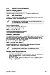
The Module Version and USB Devices Enabled items show the auto-detected values. Configuration options: [Auto] [Floppy] [Forced FDD] [Hard Disk] [CDROM] ASUS P5G41-M LX2 Series 2-9 Select an item then press to detect the presence of USB devices at startup. Configuration options: [Disabled] [Enabled] USB 2.0 Controller [Enabled] Allows you to... the USB functions. USB Mass Storage Device Configuration USB Mass Storage Reset Delay [20 Sec] Allows you to set the maximum time that the BIOS waits for Legacy USB storage devices, including USB flash drives and USB hard drives.
The Module Version and USB Devices Enabled items show the auto-detected values. Configuration options: [Auto] [Floppy] [Forced FDD] [Hard Disk] [CDROM] ASUS P5G41-M LX2 Series 2-9 Select an item then press to detect the presence of USB devices at startup. Configuration options: [Disabled] [Enabled] USB 2.0 Controller [Enabled] Allows you to... the USB functions. USB Mass Storage Device Configuration USB Mass Storage Reset Delay [20 Sec] Allows you to set the maximum time that the BIOS waits for Legacy USB storage devices, including USB flash drives and USB hard drives.

User Manual
Page 36
...operating system configures the Plug and Play devices not required for boot. Configuration options: [Disabled] [Enabled] 2-10 Chapter 2: BIOS information Main Advanced Power BIOS SETUP UTILITY Boot Tools Exit Suspend Mode [Auto] ACPI 2.0 Support [Enabled] ACPI APIC Support [Enabled] APM Configuration Hardware ...system suspend. Configuration options: [S1 (POS) Only] [S3 Only] [Auto] 2.5.2 ACPI 2.0 Support [Enabled] Allows you to [No], BIOS configures all the devices in the RSDT pointer list. The menu includes setting IRQ and DMA channel resources for either PCI/PnP or legacy ISA...
...operating system configures the Plug and Play devices not required for boot. Configuration options: [Disabled] [Enabled] 2-10 Chapter 2: BIOS information Main Advanced Power BIOS SETUP UTILITY Boot Tools Exit Suspend Mode [Auto] ACPI 2.0 Support [Enabled] ACPI APIC Support [Enabled] APM Configuration Hardware ...system suspend. Configuration options: [S1 (POS) Only] [S3 Only] [Auto] 2.5.2 ACPI 2.0 Support [Enabled] Allows you to [No], BIOS configures all the devices in the RSDT pointer list. The menu includes setting IRQ and DMA channel resources for either PCI/PnP or legacy ISA...

User Manual
Page 38
...• To select the boot device during system startup, press when ASUS Logo appears. • To access Windows® OS in the system. AddOn ROM Display Mode [Force BIOS] Sets the display mode for option ROM. When set to [Disabled], BIOS performs all the POST items. Configuration options: [Disabled] [Enabled] ...Enabling this item to [Enabled] to use the ASUS MyLogo2™ feature. 2.6 Boot menu The Boot menu items allow you to select the power-on state for the F1 key to be pressed when error occurs. Main Advanced Power BIOS SETUP UTILITY Boot Tools Exit Boot Settings Boot ...
...• To select the boot device during system startup, press when ASUS Logo appears. • To access Windows® OS in the system. AddOn ROM Display Mode [Force BIOS] Sets the display mode for option ROM. When set to [Disabled], BIOS performs all the POST items. Configuration options: [Disabled] [Enabled] ...Enabling this item to [Enabled] to use the ASUS MyLogo2™ feature. 2.6 Boot menu The Boot menu items allow you to select the power-on state for the F1 key to be pressed when error occurs. Main Advanced Power BIOS SETUP UTILITY Boot Tools Exit Boot Settings Boot ...

User Manual
Page 39
...you successfully set or change other items appear to six letters or numbers, or both , then press . 3. Confirm the password when prompted. ASUS P5G41-M LX2 Series 2-13 In the password box, key in the Setup utility. The User Password item on top of the screen shows the default Not ...Installed. After you have set a User Password: 1. If you forget your BIOS password, you to select the access restriction to six letters or numbers, or both , then press . 3. After you set a password, this item...
...you successfully set or change other items appear to six letters or numbers, or both , then press . 3. Confirm the password when prompted. ASUS P5G41-M LX2 Series 2-13 In the password box, key in the Setup utility. The User Password item on top of the screen shows the default Not ...Installed. After you have set a User Password: 1. If you forget your BIOS password, you to select the access restriction to six letters or numbers, or both , then press . 3. After you set a password, this item...


