User Manual
Page 9
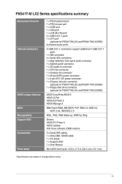
... specifications summary Back panel I/O ports Internal connectors ASUS unique features BIOS Manageability Support DVD Accessories Form factor 1 x PS/2 keyboard port 1 x PS/2 mouse port 1 x COM port 1 x VGA port 1 x LAN (RJ-45) port 4 x USB 2.0/1.1 ports 1 x LPT port (optional for P5G41T-M LX2 and P5G41T-M LX2/GB) 6-channel audio ports 2 USB 2.0/1.1 connectors support additional 4 USB 2.0/1.1 ports 1 x IDE connector 4 x Serial ATA...
... specifications summary Back panel I/O ports Internal connectors ASUS unique features BIOS Manageability Support DVD Accessories Form factor 1 x PS/2 keyboard port 1 x PS/2 mouse port 1 x COM port 1 x VGA port 1 x LAN (RJ-45) port 4 x USB 2.0/1.1 ports 1 x LPT port (optional for P5G41T-M LX2 and P5G41T-M LX2/GB) 6-channel audio ports 2 USB 2.0/1.1 connectors support additional 4 USB 2.0/1.1 ports 1 x IDE connector 4 x Serial ATA...
User Manual
Page 11
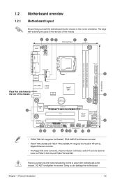
AUDIO RTL 8112L ICS 9LPRS441 Intel® G41 Lithium Cell CMOS Power PRI_IDE 7 2 24.4cm(9.6in) EATXPWR Super PCIEX16 I/O 17 P5G41T-M LX2/GB/LPT SATA4 SATA3 8Mb PCI1 Intel® SATA2 BIOS SATA1 ICH7 PCI2 8 VIA VT1705 CD FLOPPY SB_PWR USBPW5-8 USB56 USB78 CLRTC AAFP CHASSIS F_PANEL 16 15 14 4 13 12 11 10 9 •...
AUDIO RTL 8112L ICS 9LPRS441 Intel® G41 Lithium Cell CMOS Power PRI_IDE 7 2 24.4cm(9.6in) EATXPWR Super PCIEX16 I/O 17 P5G41T-M LX2/GB/LPT SATA4 SATA3 8Mb PCI1 Intel® SATA2 BIOS SATA1 ICH7 PCI2 8 VIA VT1705 CD FLOPPY SB_PWR USBPW5-8 USB56 USB78 CLRTC AAFP CHASSIS F_PANEL 16 15 14 4 13 12 11 10 9 •...
User Manual
Page 16
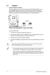
CLRTC 12 23 P5G41T-M LX2/GB/LPT Normal (Default) Clear RTC P5G41T-M LX2/GB/LPT Clear RTC RAM To erase the RTC RAM: 1. Plug the power cord and turn ON the computer. 4. After clearing the...the RTC RAM, never remove the cap on pins 2-3 for about 5-10 seconds, then move the jumper again to default values. 1-7 ASUS P5G41T-M LX2 Series Turn OFF the computer and unplug the power cord. 2. You can clear the CMOS memory of date, time, and system setup...Keep the cap on CLRTC jumper default position. Shut down the key during the boot process and enter BIOS setup to overclocking.
CLRTC 12 23 P5G41T-M LX2/GB/LPT Normal (Default) Clear RTC P5G41T-M LX2/GB/LPT Clear RTC RAM To erase the RTC RAM: 1. Plug the power cord and turn ON the computer. 4. After clearing the...the RTC RAM, never remove the cap on pins 2-3 for about 5-10 seconds, then move the jumper again to default values. 1-7 ASUS P5G41T-M LX2 Series Turn OFF the computer and unplug the power cord. 2. You can clear the CMOS memory of date, time, and system setup...Keep the cap on CLRTC jumper default position. Shut down the key during the boot process and enter BIOS setup to overclocking.
User Manual
Page 17
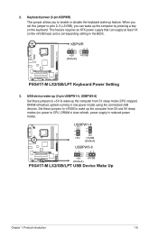
... DRAM refreshed, system running in low power mode) using the connected USB devices. KBPWR 12 23 +5V +5VSB (Default) P5G41T-M LX2/GB/LPT P5G41T-M LX2/GB/LPT Keyboard Power Setting 3. Set these jumpers to +5V to wake up the computer from S3 and S4 sleep modes (no power to ... +5V +5VSB (Default) USBPW5-8 P5G41T-M LX2/GB/LPT 12 23 +5V +5VSB (Default) P5G41T-M LX2/GB/LPT USB Device Wake Up Chapter 1: Product introduction 1-8 2. When you set this jumper to pins 2-3 (+5VSB), you to CPU, DRAM in slow refresh, power supply in the BIOS. Keyboard power (3-pin KBPWR) This jumper allows...
... DRAM refreshed, system running in low power mode) using the connected USB devices. KBPWR 12 23 +5V +5VSB (Default) P5G41T-M LX2/GB/LPT P5G41T-M LX2/GB/LPT Keyboard Power Setting 3. Set these jumpers to +5V to wake up the computer from S3 and S4 sleep modes (no power to ... +5V +5VSB (Default) USBPW5-8 P5G41T-M LX2/GB/LPT 12 23 +5V +5VSB (Default) P5G41T-M LX2/GB/LPT USB Device Wake Up Chapter 1: Product introduction 1-8 2. When you set this jumper to pins 2-3 (+5VSB), you to CPU, DRAM in slow refresh, power supply in the BIOS. Keyboard power (3-pin KBPWR) This jumper allows...
User Manual
Page 23
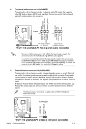
...sensor or switch cable to this connector, set the Front Panel Type item in the BIOS setup to this connector. CHASSIS +5VSB_MB Chassis Signal GND P5G41T-M LX2/GB/LPT P5G41T-M LX2/GB/LPT Chassis intrusion connector Chapter 1: Product introduction 1-14 Connect one end of the motherboard's...MIC2 MICPWR Line out_R NC Line out_L PORT1 L PORT1 R PORT2 R SENSE_SEND PORT2 L P5G41T-M LX2/GB/LPT HD-audio-compliant Legacy AC'97 pin definition compliant definition P5G41T-M LX2/GB/LPT Front panel audio connector • We recommend that supports either HD Audio or legacy AC`97...
...sensor or switch cable to this connector, set the Front Panel Type item in the BIOS setup to this connector. CHASSIS +5VSB_MB Chassis Signal GND P5G41T-M LX2/GB/LPT P5G41T-M LX2/GB/LPT Chassis intrusion connector Chapter 1: Product introduction 1-14 Connect one end of the motherboard's...MIC2 MICPWR Line out_R NC Line out_L PORT1 L PORT1 R PORT2 R SENSE_SEND PORT2 L P5G41T-M LX2/GB/LPT HD-audio-compliant Legacy AC'97 pin definition compliant definition P5G41T-M LX2/GB/LPT Front panel audio connector • We recommend that supports either HD Audio or legacy AC`97...
User Manual
Page 27
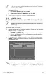
... automatically reboots the system when done. The ASUS Update utility is found, then press . Locate the BIOS file from a BIOS file a. Select Update BIOS from the ASUS website at www.asus.com. b. To update the BIOS using this utility, download the latest BIOS file from a file, then click Next....USB port, then launch EZ Flash 2 in either of updating itself through the Internet. ASUSTek EZ Flash 2 BIOS ROM Utility V3.44 FLASH TYPE: MXIC 25L8005 Current ROM BOARD:P5G41T-M LX2/GB/LPT VER:0305 (H:00 B:00) DATE: 10/29/2009 Update ROM BOARD: Unknown VER: Unknown DATE: Unknown...
... automatically reboots the system when done. The ASUS Update utility is found, then press . Locate the BIOS file from a BIOS file a. Select Update BIOS from the ASUS website at www.asus.com. b. To update the BIOS using this utility, download the latest BIOS file from a file, then click Next....USB port, then launch EZ Flash 2 in either of updating itself through the Internet. ASUSTek EZ Flash 2 BIOS ROM Utility V3.44 FLASH TYPE: MXIC 25L8005 Current ROM BOARD:P5G41T-M LX2/GB/LPT VER:0305 (H:00 B:00) DATE: 10/29/2009 Update ROM BOARD: Unknown VER: Unknown DATE: Unknown...
User Manual
Page 28
... menu for the BIOS file. Entering BIOS Setup at startup To enter BIOS Setup at www.asus.com. • The removable devices that contains the updated BIOS file. • Before using this utility, rename the BIOS file in the removable device into PG41TML2.ROM (P5G41T-M LX2) / PG41TMLG.ROM (P5G41T-M LX2/GB) / PG41TMLP.ROM (P5G41T-M LX2/GB/LPT). • The BIOS file in using...
... menu for the BIOS file. Entering BIOS Setup at startup To enter BIOS Setup at www.asus.com. • The removable devices that contains the updated BIOS file. • Before using this utility, rename the BIOS file in the removable device into PG41TML2.ROM (P5G41T-M LX2) / PG41TMLG.ROM (P5G41T-M LX2/GB) / PG41TMLP.ROM (P5G41T-M LX2/GB/LPT). • The BIOS file in using...
User Manual
Page 29
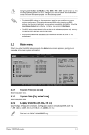
... from a running operating system can cause damage to your screen. • Visit the ASUS website at www.asus.com to download the latest BIOS file for this motherboard. 2.3 Main menu When you enter the BIOS Setup program, the Main menu screen appears, giving you see on your data or system... Select Item +- Select the Load Setups Default item under the Exit Menu. See section 2.8 Exit Menu. • The BIOS setup screens shown in .] This item is for P5G41T-M LX2/GB/LPT only. Using the power button, reset button, or the ++ keys to force reset from the operating system. • The...
... from a running operating system can cause damage to your screen. • Visit the ASUS website at www.asus.com to download the latest BIOS file for this motherboard. 2.3 Main menu When you enter the BIOS Setup program, the Main menu screen appears, giving you see on your data or system... Select Item +- Select the Load Setups Default item under the Exit Menu. See section 2.8 Exit Menu. • The BIOS setup screens shown in .] This item is for P5G41T-M LX2/GB/LPT only. Using the power button, reset button, or the ++ keys to force reset from the operating system. • The...


