User Manual
Page 1
Motherboard P5G41T-M LX2 Series • P5G41T-M LX2 • P5G41T-M LX2/GB • P5G41T-M LX2/GB/LPT
Motherboard P5G41T-M LX2 Series • P5G41T-M LX2 • P5G41T-M LX2/GB • P5G41T-M LX2/GB/LPT
User Manual
Page 8
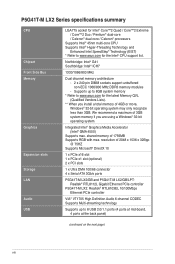
... 2 x PCI slots 1 x Ultra DMA 100/66 connector 4 x Serial ATA 3Gb/s ports P5G41T-M LX2/GB and P5G41T-M LX2/GB/LPT: Realtek® RTL8112L Gigabit Ethernet PCIe controller P5G41T-M LX2: Realtek® RTL8103EL 10/100Mbps Ethernet PCIe controller VIA® VT1705 High Definition Audio 6-channel CODEC Supports ...Multi-streaming technology Supports up to 8GB system memory * Refer to www.asus....
... 2 x PCI slots 1 x Ultra DMA 100/66 connector 4 x Serial ATA 3Gb/s ports P5G41T-M LX2/GB and P5G41T-M LX2/GB/LPT: Realtek® RTL8112L Gigabit Ethernet PCIe controller P5G41T-M LX2: Realtek® RTL8103EL 10/100Mbps Ethernet PCIe controller VIA® VT1705 High Definition Audio 6-channel CODEC Supports ...Multi-streaming technology Supports up to 8GB system memory * Refer to www.asus....
User Manual
Page 9
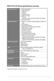
...I/O ports Internal connectors ASUS unique features BIOS Manageability Support DVD Accessories Form factor 1 x PS/2 keyboard port 1 x PS/2 mouse port 1 x COM port 1 x VGA port 1 x LAN (RJ-45) port 4 x USB 2.0/1.1 ports 1 x LPT port (optional for P5G41T-M LX2 and P5G41T-M LX2/GB) 6-channel audio ports...pin ATX 12V power connector 1 x Chassis intrusion connector (optional for P5G41T-M LX2 and P5G41T-M LX2/GB) 1 x Floppy disk drive connector (optional for P5G41T-M LX2 and P5G41T-M LX2/GB) ASUS CrashFree BIOS 3 ASUS Q-Fan ASUS EZ Flash 2 ASUS MyLogo 2 8Mb Flash ROM, AMI BIOS, PnP, DMI 2.0, WfM 2.0, ...
...I/O ports Internal connectors ASUS unique features BIOS Manageability Support DVD Accessories Form factor 1 x PS/2 keyboard port 1 x PS/2 mouse port 1 x COM port 1 x VGA port 1 x LAN (RJ-45) port 4 x USB 2.0/1.1 ports 1 x LPT port (optional for P5G41T-M LX2 and P5G41T-M LX2/GB) 6-channel audio ports...pin ATX 12V power connector 1 x Chassis intrusion connector (optional for P5G41T-M LX2 and P5G41T-M LX2/GB) 1 x Floppy disk drive connector (optional for P5G41T-M LX2 and P5G41T-M LX2/GB) ASUS CrashFree BIOS 3 ASUS Q-Fan ASUS EZ Flash 2 ASUS MyLogo 2 8Mb Flash ROM, AMI BIOS, PnP, DMI 2.0, WfM 2.0, ...
User Manual
Page 10
..., and hardware devices on it on them due to static electricity. • Hold components by the edges to page ix for buying an ASUS® P5G41T-M LX2 Series motherboard! Onboard LED The motherboard comes with the component. • Before you install or remove any motherboard settings. • Unplug the... precautions before you install motherboard components or change any component, ensure that lights up to the motherboard, peripherals, or components. SB_PWR P5G41T-M LX2/GB/LPT ON OFF Standby Power Powered Off P5G41T-M LX2/GB/LPT Onboard power LED 1-1 ASUS P5G41T-M LX2 Series
..., and hardware devices on it on them due to static electricity. • Hold components by the edges to page ix for buying an ASUS® P5G41T-M LX2 Series motherboard! Onboard LED The motherboard comes with the component. • Before you install or remove any motherboard settings. • Unplug the... precautions before you install motherboard components or change any component, ensure that lights up to the motherboard, peripherals, or components. SB_PWR P5G41T-M LX2/GB/LPT ON OFF Standby Power Powered Off P5G41T-M LX2/GB/LPT Onboard power LED 1-1 ASUS P5G41T-M LX2 Series
User Manual
Page 11
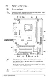
...8112L ICS 9LPRS441 Intel® G41 Lithium Cell CMOS Power PRI_IDE 7 2 24.4cm(9.6in) EATXPWR Super PCIEX16 I/O 17 P5G41T-M LX2/GB/LPT SATA4 SATA3 8Mb PCI1 Intel® SATA2 BIOS SATA1 ICH7 PCI2 8 VIA VT1705 CD FLOPPY SB_PWR USBPW5-8 USB56 USB78 CLRTC AAFP ...CHASSIS F_PANEL 16 15 14 4 13 12 11 10 9 • P5G41T-M LX2 integrates the Realtek® RTL8103EL Fast Ethernet controller. • P5G41T-M LX2/GB and P5G41T-M LX2/GB/LPT integrate the Realtek® RTL8112L Gigabit Ethernet controller. • The floppy disk drive connector, chassis...
...8112L ICS 9LPRS441 Intel® G41 Lithium Cell CMOS Power PRI_IDE 7 2 24.4cm(9.6in) EATXPWR Super PCIEX16 I/O 17 P5G41T-M LX2/GB/LPT SATA4 SATA3 8Mb PCI1 Intel® SATA2 BIOS SATA1 ICH7 PCI2 8 VIA VT1705 CD FLOPPY SB_PWR USBPW5-8 USB56 USB78 CLRTC AAFP ...CHASSIS F_PANEL 16 15 14 4 13 12 11 10 9 • P5G41T-M LX2 integrates the Realtek® RTL8103EL Fast Ethernet controller. • P5G41T-M LX2/GB and P5G41T-M LX2/GB/LPT integrate the Realtek® RTL8112L Gigabit Ethernet controller. • The floppy disk drive connector, chassis...

User Manual
Page 13
... motherboard. • This motherboard does not support DIMMs made up of the DDR3 DIMM sockets: DIMM_A1 DIMM_B1 Channel Channel A Channel B Sockets DIMM_A1 DIMM_B1 P5G41T-M LX2/GB/LPT P5G41T-M LX2/GB/LPT 240-pin DDR3 DIMM sockets 1.4.2 Memory configurations You may install 512MB, 1GB, 2GB, and 4GB unbuffered non‑ECC DDR3 DIMMs into the DIMM sockets...
... motherboard. • This motherboard does not support DIMMs made up of the DDR3 DIMM sockets: DIMM_A1 DIMM_B1 Channel Channel A Channel B Sockets DIMM_A1 DIMM_B1 P5G41T-M LX2/GB/LPT P5G41T-M LX2/GB/LPT 240-pin DDR3 DIMM sockets 1.4.2 Memory configurations You may install 512MB, 1GB, 2GB, and 4GB unbuffered non‑ECC DDR3 DIMMs into the DIMM sockets...
User Manual
Page 16
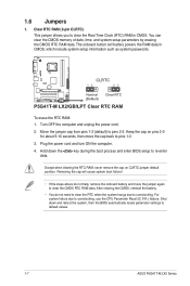
... the battery. • You do not help, remove the onboard battery and move the cap back to default values. 1-7 ASUS P5G41T-M LX2 Series CLRTC 12 23 P5G41T-M LX2/GB/LPT Normal (Default) Clear RTC P5G41T-M LX2/GB/LPT Clear RTC RAM To erase the RTC RAM: 1. Turn OFF the computer and unplug the power cord. 2. The onboard button...
... the battery. • You do not help, remove the onboard battery and move the cap back to default values. 1-7 ASUS P5G41T-M LX2 Series CLRTC 12 23 P5G41T-M LX2/GB/LPT Normal (Default) Clear RTC P5G41T-M LX2/GB/LPT Clear RTC RAM To erase the RTC RAM: 1. Turn OFF the computer and unplug the power cord. 2. The onboard button...
User Manual
Page 17
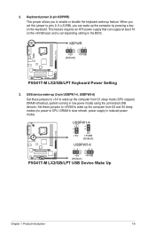
... you set this jumper to pins 2-3 (+5VSB), you to wake up feature. KBPWR 12 23 +5V +5VSB (Default) P5G41T-M LX2/GB/LPT P5G41T-M LX2/GB/LPT Keyboard Power Setting 3. USB device wake-up (3-pin USBPW1-4, USBPW5-8) Set these jumpers to +5VSB to enable or disable the keyboard wake...(CPU stopped, DRAM refreshed, system running in the BIOS. USBPW1-4 12 23 +5V +5VSB (Default) USBPW5-8 P5G41T-M LX2/GB/LPT 12 23 +5V +5VSB (Default) P5G41T-M LX2/GB/LPT USB Device Wake Up Chapter 1: Product introduction 1-8 2. Keyboard power (3-pin KBPWR) This jumper allows you can supply at least...
... you set this jumper to pins 2-3 (+5VSB), you to wake up feature. KBPWR 12 23 +5V +5VSB (Default) P5G41T-M LX2/GB/LPT P5G41T-M LX2/GB/LPT Keyboard Power Setting 3. USB device wake-up (3-pin USBPW1-4, USBPW5-8) Set these jumpers to +5VSB to enable or disable the keyboard wake...(CPU stopped, DRAM refreshed, system running in the BIOS. USBPW1-4 12 23 +5V +5VSB (Default) USBPW5-8 P5G41T-M LX2/GB/LPT 12 23 +5V +5VSB (Default) P5G41T-M LX2/GB/LPT USB Device Wake Up Chapter 1: Product introduction 1-8 2. Keyboard power (3-pin KBPWR) This jumper allows you can supply at least...
User Manual
Page 18
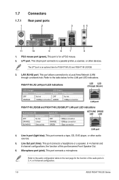
...connection LED (Green) Status OFF GREEN Description No link 10Mbps connection LED LED (Orange) (Green) LAN port P5G41T-M LX2/GB and P5G41T-M LX2/GB/LPT LAN port LED indications Activity/Link LED Status Description OFF No link ORANGE Linked BLINKING Data activity Speed LED Status OFF...4. Line Out port (lime). In 4-channel and 6-channel configurations, the function of the audio ports in 2, 4, or 6-channel configuration. 1-9 ASUS P5G41T-M LX2 Series This port is an optional item for the LAN port LED indications. This port connects a headphone or a speaker. Refer to a parallel ...
...connection LED (Green) Status OFF GREEN Description No link 10Mbps connection LED LED (Orange) (Green) LAN port P5G41T-M LX2/GB and P5G41T-M LX2/GB/LPT LAN port LED indications Activity/Link LED Status Description OFF No link ORANGE Linked BLINKING Data activity Speed LED Status OFF...4. Line Out port (lime). In 4-channel and 6-channel configurations, the function of the audio ports in 2, 4, or 6-channel configuration. 1-9 ASUS P5G41T-M LX2 Series This port is an optional item for the LAN port LED indications. This port connects a headphone or a speaker. Refer to a parallel ...

User Manual
Page 19
... Volts Power OK -5 Volts PIN 1 GND +5 Volts GND GND GND GND GND GND P5G41T-M LX2/GB/LPT +5 Volts GND PSON# GND +3 Volts -12 Volts +3 Volts +3 Volts PIN 1 P5G41T-M LX2/GB/LPT ATX power connectors • For a fully configured system, we recommend that complies with more power-...consuming devices or when you intend to the Recommended Power Supply Wattage Calculator at http://support.asus. The system may become unstable or...
... Volts Power OK -5 Volts PIN 1 GND +5 Volts GND GND GND GND GND GND P5G41T-M LX2/GB/LPT +5 Volts GND PSON# GND +3 Volts -12 Volts +3 Volts +3 Volts PIN 1 P5G41T-M LX2/GB/LPT ATX power connectors • For a fully configured system, we recommend that complies with more power-...consuming devices or when you intend to the Recommended Power Supply Wattage Calculator at http://support.asus. The system may become unstable or...
User Manual
Page 20
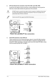
... GND SATA3 GND RSATA_RXN2 RSATA_RXP2 GND RSATA_TXN2 RSATA_TXP2 GND GND RSATA_RXN1 RSATA_RXP1 GND RSATA_TXN1 RSATA_TXP1 GND P5G41T-M LX2/GB/LPT SATA2 SATA1 P5G41T-M LX2/GB/LPT SATA connectors 1-11 ASUS P5G41T-M LX2 Series Do not place jumper caps on the motherboard, ensuring that the black wire of each cable ...may damage the motherboard components. Only the 4-pin CPU fan supports the ASUS Q-Fan feature. P5G41T-M LX2/GB/LPT CHA_FAN Rotation +12V GND CPU_FAN CPU FAN PWM CPU FAN IN CPU FAN PWR GND P5G41T-M LX2/GB/LPT fan connectors 3. 2. DO NOT forget to connect the fan cables to...
... GND SATA3 GND RSATA_RXN2 RSATA_RXP2 GND RSATA_TXN2 RSATA_TXP2 GND GND RSATA_RXN1 RSATA_RXP1 GND RSATA_TXN1 RSATA_TXP1 GND P5G41T-M LX2/GB/LPT SATA2 SATA1 P5G41T-M LX2/GB/LPT SATA connectors 1-11 ASUS P5G41T-M LX2 Series Do not place jumper caps on the motherboard, ensuring that the black wire of each cable ...may damage the motherboard components. Only the 4-pin CPU fan supports the ASUS Q-Fan feature. P5G41T-M LX2/GB/LPT CHA_FAN Rotation +12V GND CPU_FAN CPU FAN PWM CPU FAN IN CPU FAN PWR GND P5G41T-M LX2/GB/LPT fan connectors 3. 2. DO NOT forget to connect the fan cables to...
User Manual
Page 21
...:Orient the red markings on the Ultra DMA cable connector. Connect the blue connector to configure your device. P5G41T-M LX2/GB/LPT IDE connector Single device Two devices Drive jumper setting Cable-Select or Master Cable-Select Master Slave Mode of the following modes to the motherboard's ... are three connectors on each Ultra DMA 100/66 signal cable: blue, black, and gray. CD Right Audio Channel GND GND Left Audio Channel P5G41T-M LX2/GB/LPT P5G41T-M LX2/GB/LPT Internal audio connector Chapter 1: Product introduction 1-12
...:Orient the red markings on the Ultra DMA cable connector. Connect the blue connector to configure your device. P5G41T-M LX2/GB/LPT IDE connector Single device Two devices Drive jumper setting Cable-Select or Master Cable-Select Master Slave Mode of the following modes to the motherboard's ... are three connectors on each Ultra DMA 100/66 signal cable: blue, black, and gray. CD Right Audio Channel GND GND Left Audio Channel P5G41T-M LX2/GB/LPT P5G41T-M LX2/GB/LPT Internal audio connector Chapter 1: Product introduction 1-12
User Manual
Page 22
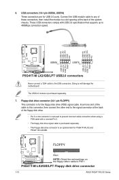
P5G41T-M LX2/GB/LPT Floppy disk drive connector 1-13 ASUS P5G41T-M LX2 Series FLOPPY P5G41T-M LX2/GB/LPT PIN 1 NOTE: Orient the red markings on the connector is an optional item for P5G41T-M LX2 and P5G41T-M LX2/GB. Doing so will damage the motherboard! These USB connectors comply with a covered Pin 5. •... to PIN 1. USB+5V USB_P8USB_P8+ GND NC USB+5V USB_P6USB_P6+ GND NC P5G41T-M LX2/GB/LPT USB56 PIN 1 USB78 PIN 1 USB+5V USB_P7USB_P7+ GND USB+5V USB_P5USB_P5+ GND P5G41T-M LX2/GB/LPT USB2.0 connectors Never connect a 1394 cable to a slot opening at the back of ...
P5G41T-M LX2/GB/LPT Floppy disk drive connector 1-13 ASUS P5G41T-M LX2 Series FLOPPY P5G41T-M LX2/GB/LPT PIN 1 NOTE: Orient the red markings on the connector is an optional item for P5G41T-M LX2 and P5G41T-M LX2/GB. Doing so will damage the motherboard! These USB connectors comply with a covered Pin 5. •... to PIN 1. USB+5V USB_P8USB_P8+ GND NC USB+5V USB_P6USB_P6+ GND NC P5G41T-M LX2/GB/LPT USB56 PIN 1 USB78 PIN 1 USB+5V USB_P7USB_P7+ GND USB+5V USB_P5USB_P5+ GND P5G41T-M LX2/GB/LPT USB2.0 connectors Never connect a 1394 cable to a slot opening at the back of ...
User Manual
Page 23
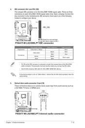
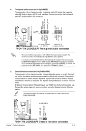
...connector to avail of the chassis intrusion sensor or switch cable to [HD Audio]. CHASSIS +5VSB_MB Chassis Signal GND P5G41T-M LX2/GB/LPT P5G41T-M LX2/GB/LPT Chassis intrusion connector Chapter 1: Product introduction 1-14 Front panel audio connector (10-1 pin AAFP) This connector is for details...MIC2 MICPWR Line out_R NC Line out_L PORT1 L PORT1 R PORT2 R SENSE_SEND PORT2 L P5G41T-M LX2/GB/LPT HD-audio-compliant Legacy AC'97 pin definition compliant definition P5G41T-M LX2/GB/LPT Front panel audio connector • We recommend that supports either HD Audio or legacy AC`97 ...
...connector to avail of the chassis intrusion sensor or switch cable to [HD Audio]. CHASSIS +5VSB_MB Chassis Signal GND P5G41T-M LX2/GB/LPT P5G41T-M LX2/GB/LPT Chassis intrusion connector Chapter 1: Product introduction 1-14 Front panel audio connector (10-1 pin AAFP) This connector is for details...MIC2 MICPWR Line out_R NC Line out_L PORT1 L PORT1 R PORT2 R SENSE_SEND PORT2 L P5G41T-M LX2/GB/LPT HD-audio-compliant Legacy AC'97 pin definition compliant definition P5G41T-M LX2/GB/LPT Front panel audio connector • We recommend that supports either HD Audio or legacy AC`97 ...
User Manual
Page 24
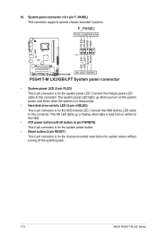
... the HDD Activity LED. F_PANEL PWR LED PWR BTN PIN 1 P5G41T-M LX2/GB/LPT HD LED RESET P5G41T-M LX2/GB/LPT System panel connector • System power LED (2-pin PLED) This 2-pin connector is for system reboot without turning off the system power. 1-15 ASUS P5G41T-M LX2 Series The HD LED lights up when you turn on the...
... the HDD Activity LED. F_PANEL PWR LED PWR BTN PIN 1 P5G41T-M LX2/GB/LPT HD LED RESET P5G41T-M LX2/GB/LPT System panel connector • System power LED (2-pin PLED) This 2-pin connector is for system reboot without turning off the system power. 1-15 ASUS P5G41T-M LX2 Series The HD LED lights up when you turn on the...
User Manual
Page 27
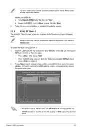
...the latest BIOS file to prevent system boot failure! ASUSTek EZ Flash 2 BIOS ROM Utility V3.44 FLASH TYPE: MXIC 25L8005 Current ROM BOARD:P5G41T-M LX2/GB/LPT VER:0305 (H:00 B:00) DATE: 10/29/2009 Update ROM BOARD: Unknown VER: Unknown DATE: Unknown PATH: A:\ A: Note [Enter] Select... program. Follow the onscreen instructions to update the BIOS without using EZ Flash 2: 1. Before you to complete the updating process. 2.1.2 ASUS EZ Flash 2 The ASUS EZ Flash 2 feature allows you start using this utility, download the latest BIOS file from a BIOS file a. EZ Flash 2 performs...
...the latest BIOS file to prevent system boot failure! ASUSTek EZ Flash 2 BIOS ROM Utility V3.44 FLASH TYPE: MXIC 25L8005 Current ROM BOARD:P5G41T-M LX2/GB/LPT VER:0305 (H:00 B:00) DATE: 10/29/2009 Update ROM BOARD: Unknown VER: Unknown DATE: Unknown PATH: A:\ A: Note [Enter] Select... program. Follow the onscreen instructions to update the BIOS without using EZ Flash 2: 1. Before you to complete the updating process. 2.1.2 ASUS EZ Flash 2 The ASUS EZ Flash 2 feature allows you start using this utility, download the latest BIOS file from a BIOS file a. EZ Flash 2 performs...
User Manual
Page 28
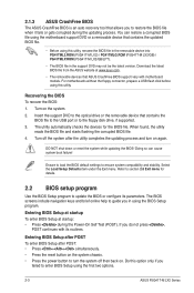
...Press the power button to turn on the system. 2. Doing so can restore a corrupted BIOS file using the first two options. 2-3 ASUS P5G41T-M LX2 Series Turn on again. DO NOT shut down or reset the system while updating the BIOS! Ensure to load the BIOS default settings to... BIOS file in the removable device into PG41TML2.ROM (P5G41T-M LX2) / PG41TMLG.ROM (P5G41T-M LX2/GB) / PG41TMLP.ROM (P5G41T-M LX2/GB/LPT). • The BIOS file in the support DVD may not be the latest version. 2.1.3 ASUS CrashFree BIOS The ASUS CrashFree BIOS is an auto recovery tool that contains the BIOS ...
...Press the power button to turn on the system. 2. Doing so can restore a corrupted BIOS file using the first two options. 2-3 ASUS P5G41T-M LX2 Series Turn on again. DO NOT shut down or reset the system while updating the BIOS! Ensure to load the BIOS default settings to... BIOS file in the removable device into PG41TML2.ROM (P5G41T-M LX2) / PG41TMLG.ROM (P5G41T-M LX2/GB) / PG41TMLP.ROM (P5G41T-M LX2/GB/LPT). • The BIOS file in the support DVD may not be the latest version. 2.1.3 ASUS CrashFree BIOS The ASUS CrashFree BIOS is an auto recovery tool that contains the BIOS ...
User Manual
Page 29
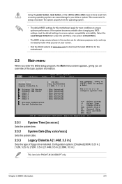
... installed. We recommend to always shut down the system properly from a running operating system can cause damage to your screen. • Visit the ASUS website at www.asus.com to download the latest BIOS file for this motherboard. 2.3 Main menu When you enter the BIOS Setup program, the Main menu screen appears... power button, reset button, or the ++ keys to force reset from the operating system. • The default BIOS settings for this motherboard apply for P5G41T-M LX2/GB/LPT only.
... installed. We recommend to always shut down the system properly from a running operating system can cause damage to your screen. • Visit the ASUS website at www.asus.com to download the latest BIOS file for this motherboard. 2.3 Main menu When you enter the BIOS Setup program, the Main menu screen appears... power button, reset button, or the ++ keys to force reset from the operating system. • The default BIOS settings for this motherboard apply for P5G41T-M LX2/GB/LPT only.
User Manual
Page 34
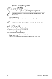
... item is for P5G41T-M LX2/GB/LPT with an LPT port at the back panel. Parallel Port Address [378] Allows you to select the Parallel Port mode. Serial Port1 Mode [Normal] Selects the mode for P5G41T-M LX2 and P5G41T-M LX2/GB without an LPT port at the back panel. Configuration options: [IRQ5] [IRQ7] 2-9 ASUS P5G41T-M LX2 Series Configuration options: [Normal...
... item is for P5G41T-M LX2/GB/LPT with an LPT port at the back panel. Parallel Port Address [378] Allows you to select the Parallel Port mode. Serial Port1 Mode [Normal] Selects the mode for P5G41T-M LX2 and P5G41T-M LX2/GB without an LPT port at the back panel. Configuration options: [IRQ5] [IRQ7] 2-9 ASUS P5G41T-M LX2 Series Configuration options: [Normal...

