
User Manual
Page 25
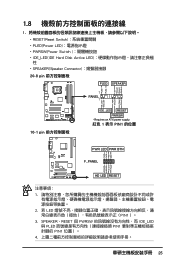
SPEAKER、RESET 與 PWRSW IDE_LED 與 PLED PIN1 PIN1 4 25 1.8 1 RESET(Reset Switch PLED(Power LED PWRSW(Power Switch IDE_LED(IDE Hard Disk Active LED SPEAKER(Speaker Connector 20-8 pin PLED SPEAKER 1 PANEL1 PLED+ PLED+5V Ground Ground Speaker P5B-E ® IDE_LED+ IDE_LED- PWR Ground Reset ...
SPEAKER、RESET 與 PWRSW IDE_LED 與 PLED PIN1 PIN1 4 25 1.8 1 RESET(Reset Switch PLED(Power LED PWRSW(Power Switch IDE_LED(IDE Hard Disk Active LED SPEAKER(Speaker Connector 20-8 pin PLED SPEAKER 1 PANEL1 PLED+ PLED+5V Ground Ground Speaker P5B-E ® IDE_LED+ IDE_LED- PWR Ground Reset ...

User Manual
Page 4
... a bootable floppy disk 2-2 2.1.2 ASUS EZ Flash 2 utility 2-3 2.1.3 AFUDOS utility 2-4 2.1.4 ASUS CrashFree BIOS 3 utility 2-6 2.1.5 ASUS Update utility 2-8 2.2 BIOS setup program... 2-11 2.2.1 BIOS menu screen 2-12 2.2.2 Menu bar 2-12 2.2.3 Navigation keys 2-12 2.2.4 Menu items 2-13 2.2.5 Sub-menu items 2-13 2.2.6 Configuration fields 2-13 2.2.7 Pop-up window 2-13 2.2.8 Scroll bar 2-13 2.2.9 General help 2-13 2.3 Main menu 2-14 2.3.1 System Time 2-14 2.3.2 System Date 2-14 2.3.3 Legacy Diskette A 2-14 2.3.4 SATA1-6 2-15 2.3.5 IDE...
... a bootable floppy disk 2-2 2.1.2 ASUS EZ Flash 2 utility 2-3 2.1.3 AFUDOS utility 2-4 2.1.4 ASUS CrashFree BIOS 3 utility 2-6 2.1.5 ASUS Update utility 2-8 2.2 BIOS setup program... 2-11 2.2.1 BIOS menu screen 2-12 2.2.2 Menu bar 2-12 2.2.3 Navigation keys 2-12 2.2.4 Menu items 2-13 2.2.5 Sub-menu items 2-13 2.2.6 Configuration fields 2-13 2.2.7 Pop-up window 2-13 2.2.8 Scroll bar 2-13 2.2.9 General help 2-13 2.3 Main menu 2-14 2.3.1 System Time 2-14 2.3.2 System Date 2-14 2.3.3 Legacy Diskette A 2-14 2.3.4 SATA1-6 2-15 2.3.5 IDE...
User Manual
Page 12
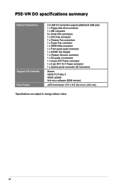
P5E-VM DO specifications summary Internal Connectors Support CD Contents Form Factor 4 x USB 2.0 connectors support additional 8 USB ports 1 x Floppy disk drive connector 1 x IDE connector 6 x Serial ATA ...connectors 1 x CPU Fan connector 1 x Chassis Fan connectors 1 x Power Fan connector 1 x IEEE1394a connector 1 x Front panel audio connector 1 x S/PDIF Out Header 1 x Chassis intrusion connector 1 x CD audio in connector 1 x 24-pin ATX Power connector 1 x 4-pin ATX 12 V Power connector 1 x System panel connector (Q-Connector) Drivers ASUS PC Probe II ASUS...
P5E-VM DO specifications summary Internal Connectors Support CD Contents Form Factor 4 x USB 2.0 connectors support additional 8 USB ports 1 x Floppy disk drive connector 1 x IDE connector 6 x Serial ATA ...connectors 1 x CPU Fan connector 1 x Chassis Fan connectors 1 x Power Fan connector 1 x IEEE1394a connector 1 x Front panel audio connector 1 x S/PDIF Out Header 1 x Chassis intrusion connector 1 x CD audio in connector 1 x 24-pin ATX Power connector 1 x 4-pin ATX 12 V Power connector 1 x System panel connector (Q-Connector) Drivers ASUS PC Probe II ASUS...
User Manual
Page 23
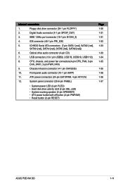
... button/soft-off button (2-pin PWRSW) • Reset button (2-pin RESET) Page 1-30 1-31 1-31 1-32 1-33 1-33 1-34 1-35 1-35 1-36 1-36 1-37 ASUS P5E-VM DO 1-11 IDE connector (40-1 pin PRI_IDE) 5. ATX power connectors (24-pin EATXPWR, 4-pin ATX12V) 12. USB connectors (10-1 pin USB56, USB 78, USB910, USB1112) 8. IEEE 1394a...
... button/soft-off button (2-pin PWRSW) • Reset button (2-pin RESET) Page 1-30 1-31 1-31 1-32 1-33 1-33 1-34 1-35 1-35 1-36 1-36 1-37 ASUS P5E-VM DO 1-11 IDE connector (40-1 pin PRI_IDE) 5. ATX power connectors (24-pin EATXPWR, 4-pin ATX12V) 12. USB connectors (10-1 pin USB56, USB 78, USB910, USB1112) 8. IEEE 1394a...

User Manual
Page 37
... for PCI steering* 11 6 IRQ holder for PCI steering* 12 7 PS/2 Compatible Mouse Port* 13 8 Numeric Data Processor 14 9 Primary IDE Channel 15 10 Secondary IDE Channel * These IRQs are usually available for ISA or PCI devices. ASUS P5E-VM DO 1-25 1.8.3 Interrupt assignments Standard interrupt assignments IRQ Priority Standard function 0 1 System Timer 1 2 Keyboard Controller 2 -
... for PCI steering* 11 6 IRQ holder for PCI steering* 12 7 PS/2 Compatible Mouse Port* 13 8 Numeric Data Processor 14 9 Primary IDE Channel 15 10 Secondary IDE Channel * These IRQs are usually available for ISA or PCI devices. ASUS P5E-VM DO 1-25 1.8.3 Interrupt assignments Standard interrupt assignments IRQ Priority Standard function 0 1 System Timer 1 2 Keyboard Controller 2 -
User Manual
Page 38
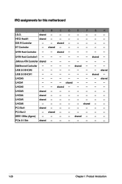
... - - - - - - - shared - - - - - - USB 2.0 EHCI#0 - - - - - - - UHCI#2 - - shared - - shared - - - - - - - - - shared - SATA Host Controller - - UHCI#3 shared - - - - - - - shared - - - PCI Slot1 shared - - - - - - - IRQ assignments for this motherboard I.G.D. GbEthernet Controller - - - - HECI Host#1 IDE-R Controller KT Controller A B C D E F G H shared - - - - - - - SATA Host Controller1 - - - - - -
... - - - - - - - shared - - - - - - USB 2.0 EHCI#0 - - - - - - - UHCI#2 - - shared - - shared - - - - - - - - - shared - SATA Host Controller - - UHCI#3 shared - - - - - - - shared - - - PCI Slot1 shared - - - - - - - IRQ assignments for this motherboard I.G.D. GbEthernet Controller - - - - HECI Host#1 IDE-R Controller KT Controller A B C D E F G H shared - - - - - - - SATA Host Controller1 - - - - - -
User Manual
Page 44
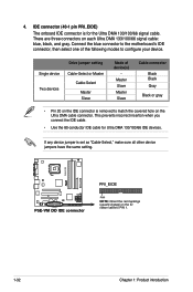
... the ID ribbon cable to configure your device. This prevents incorrect insertion when you connect the IDE cable. • Use the 80-conductor IDE cable for the Ultra DMA 133/100/66 signal cable. P5E-VM DO R P5E-VM DO IDE connector PRI_EIDE PIN1 NOTE: Orient the red markings (usually zigzag) on each Ultra DMA 133/100...
... the ID ribbon cable to configure your device. This prevents incorrect insertion when you connect the IDE cable. • Use the 80-conductor IDE cable for the Ultra DMA 133/100/66 signal cable. P5E-VM DO R P5E-VM DO IDE connector PRI_EIDE PIN1 NOTE: Orient the red markings (usually zigzag) on each Ultra DMA 133/100...
User Manual
Page 49
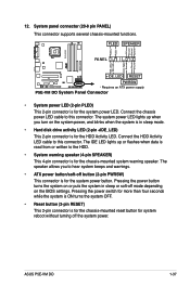
... chassis power LED cable to this connector. The IDE LED lights up when you to the HDD. • System warning speaker (4-pin SPEAKER) This 4-pin connector is for the HDD Activity LED. PLED SPEAKER PA NEL +IDE_LED RESET PWRSW * Requires an ATX power supply P5E-VM DO System Panel Connector • System power... the chassis-mounted system warning speaker. System panel connector (20-8 pin PANEL) This connector supports several chassis-mounted functions. PLED+ PLED+5V Ground Ground Speaker P5E-VM DO R IDE_LED+ IDE_LED- ASUS P5E-VM DO 1-37
... chassis power LED cable to this connector. The IDE LED lights up when you to the HDD. • System warning speaker (4-pin SPEAKER) This 4-pin connector is for the HDD Activity LED. PLED SPEAKER PA NEL +IDE_LED RESET PWRSW * Requires an ATX power supply P5E-VM DO System Panel Connector • System power... the chassis-mounted system warning speaker. System panel connector (20-8 pin PANEL) This connector supports several chassis-mounted functions. PLED+ PLED+5V Ground Ground Speaker P5E-VM DO R IDE_LED+ IDE_LED- ASUS P5E-VM DO 1-37
User Manual
Page 62
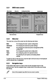
... configuring options for that particular menu. Select Screen Select Item +- Use the navigation keys to select items in ] SATA 1 SATA 2 SATA 3 SATA 4 SATA 5 SATA 6 IDE Primary Master IDE Primary Slave IDER Primary Master IDER Primary Slave SATA Configuration System Information :[Not Detected] :[Not Detected] :[Not Detected] :[Not Detected] :[Not Detected] :[Not Detected...
... configuring options for that particular menu. Select Screen Select Item +- Use the navigation keys to select items in ] SATA 1 SATA 2 SATA 3 SATA 4 SATA 5 SATA 6 IDE Primary Master IDE Primary Slave IDER Primary Master IDER Primary Slave SATA Configuration System Information :[Not Detected] :[Not Detected] :[Not Detected] :[Not Detected] :[Not Detected] :[Not Detected...

User Manual
Page 63
... fit on the screen. configurable, you can change the value of a field, select it then press to display a pop-up window Scroll bar ASUS P5E-VM DO 2-13 You cannot select an item that the iteam has a sub-menu. Pop-up window with the configuration options for the menu items.... on the menu bar have their respective menu items. System Time System Date Legacy Diskette A SATA 1 SATA 2 SATA 3 SATA 4 SATA 5 SATA 6 IDE Primary Master IDE Primary Slave IDER Primary Master IDER Primary Slave SATA Configuration System Information [06:22:54] [Fri 08/10/2007] [1.44M, 3.5 in brackets, and is...
... fit on the screen. configurable, you can change the value of a field, select it then press to display a pop-up window Scroll bar ASUS P5E-VM DO 2-13 You cannot select an item that the iteam has a sub-menu. Pop-up window with the configuration options for the menu items.... on the menu bar have their respective menu items. System Time System Date Legacy Diskette A SATA 1 SATA 2 SATA 3 SATA 4 SATA 5 SATA 6 IDE Primary Master IDE Primary Slave IDER Primary Master IDER Primary Slave SATA Configuration System Information [06:22:54] [Fri 08/10/2007] [1.44M, 3.5 in brackets, and is...
User Manual
Page 64
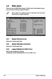
... When you enter the BIOS Setup program, the Main menu screen appears, giving you to navigate through them. SATA 1 SATA 2 SATA 3 SATA 4 SATA 5 SATA 6 IDE Primary Master IDE Primary Slave IDER Primary Master IDER Primary Slave SATA Configuration System Information :[Not Detected] :[Not Detected] :[Not Detected] :[Not Detected] :[Not Detected] :[Not Detected...
... When you enter the BIOS Setup program, the Main menu screen appears, giving you to navigate through them. SATA 1 SATA 2 SATA 3 SATA 4 SATA 5 SATA 6 IDE Primary Master IDE Primary Slave IDER Primary Master IDER Primary Slave SATA Configuration System Information :[Not Detected] :[Not Detected] :[Not Detected] :[Not Detected] :[Not Detected] :[Not Detected...
User Manual
Page 65
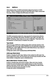
When set to [Disabled], the data transfer from and to Auto allows automatic selection of SATA devices. Configuration options: [Disabled] [Auto] ASUS P5E-VM DO 2-15 2.3.4 SATA1-6 While entering Setup, the BIOS automatically detects the presence of the appropriate SATA device type. Setting to the device occurs multiple sectors ... if the device supports this mode, and if the device was not previously formatted with LBA mode disabled. There is a separate sub-menu for each IDE device.
When set to [Disabled], the data transfer from and to Auto allows automatic selection of SATA devices. Configuration options: [Disabled] [Auto] ASUS P5E-VM DO 2-15 2.3.4 SATA1-6 While entering Setup, the BIOS automatically detects the presence of the appropriate SATA device type. Setting to the device occurs multiple sectors ... if the device supports this mode, and if the device was not previously formatted with LBA mode disabled. There is a separate sub-menu for each IDE device.
User Manual
Page 66
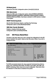
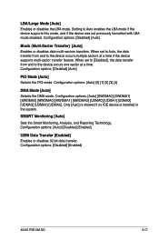
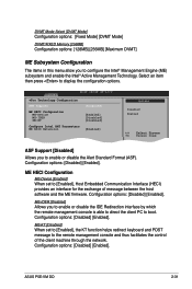
... [Auto] [Disabled] [Enabled] 32Bit Data Transfer [Enabled] Enables or disables 32-bit data transfer. Only [Auto] is showed if no IDE device is installed in the system. 2-16 Chapter 2: BIOS setup SMART Monitoring [Auto] Sets the Smart Monitoring, Analysis, and Reporting Technology. ...items (Device, Vendor, Size, LBA Mode, Block Mode, PIO Mode, Async DMA, Ultra DMA, and SMART monitoring). Configuration options: [Disabled] [Enabled] 2.3.5 IDE Primary Master/Slave The items in the system. PIO Mode [Auto] Selects the PIO mode. Configuration options: [Auto] [0] [1] [2] [3] [4] DMA Mode [...
... [Auto] [Disabled] [Enabled] 32Bit Data Transfer [Enabled] Enables or disables 32-bit data transfer. Only [Auto] is showed if no IDE device is installed in the system. 2-16 Chapter 2: BIOS setup SMART Monitoring [Auto] Sets the Smart Monitoring, Analysis, and Reporting Technology. ...items (Device, Vendor, Size, LBA Mode, Block Mode, PIO Mode, Async DMA, Ultra DMA, and SMART monitoring). Configuration options: [Disabled] [Enabled] 2.3.5 IDE Primary Master/Slave The items in the system. PIO Mode [Auto] Selects the PIO mode. Configuration options: [Auto] [0] [1] [2] [3] [4] DMA Mode [...
User Manual
Page 67
...at a time. Configuration options: [Disabled] [Auto] PIO Mode [Auto] Selects the PIO mode. Configuration options: [Disabled] [Enabled] ASUS P5E-VM DO 2-17 Setting to the device occurs one sector at a time if the device supports multi-sector transfer feature. Configuration options: [Auto... options: [Disabled] [Auto] Block (Multi-Sector Transfer) [Auto] Enables or disables data multi-sectors transfers. Only [Auto] is showed if no IDE device is installed in the system. Configuration options: [Auto] [SWDMA0] [SWDMA1] [SWDMA2] [MWDMA0] [MWDMA1] [MWDMA2] [UDMA0] [UDMA1] ...
...at a time. Configuration options: [Disabled] [Auto] PIO Mode [Auto] Selects the PIO mode. Configuration options: [Disabled] [Enabled] ASUS P5E-VM DO 2-17 Setting to the device occurs one sector at a time if the device supports multi-sector transfer feature. Configuration options: [Auto... options: [Disabled] [Auto] Block (Multi-Sector Transfer) [Auto] Enables or disables data multi-sectors transfers. Only [Auto] is showed if no IDE device is installed in the system. Configuration options: [Auto] [SWDMA0] [SWDMA1] [SWDMA2] [MWDMA0] [MWDMA1] [MWDMA2] [UDMA0] [UDMA1] ...
User Manual
Page 69
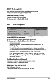
... allowing the drive to enable or disable the hard disk write protect. Configuration options: [0] [5] [10] [15] [20] [25] [30] [35] ASUS P5E-VM DO 2-19 Configuration options: [Disabled] [Compatible] [Enhanced] Configure SATA as [IDE] Hard Disk Write Protect [Disabled] SATA Detect Time Out (Sec) [35] Options Disabled Compatible Enhanced SATA Configuration [Enhanced] Allows you...
... allowing the drive to enable or disable the hard disk write protect. Configuration options: [0] [5] [10] [15] [20] [25] [30] [35] ASUS P5E-VM DO 2-19 Configuration options: [Disabled] [Compatible] [Enhanced] Configure SATA as [IDE] Hard Disk Write Protect [Disabled] SATA Detect Time Out (Sec) [35] Options Disabled Compatible Enhanced SATA Configuration [Enhanced] Allows you...
User Manual
Page 81
... item then press to configure the Intel® Management Engine (ME) subsystem and enable the Intel® Active Management Technology. ASUS P5E-VM DO 2-31 vPro Technology Configuration ASF Support ME HECI Configuration ME-Device ME-IDER ME-KT Configure Intel AMT Parameters ME BIOS...] [Enabled] [Disabled] [Disabled] [Enabled] Options Disabled Enabled ASF Support [Disabled] Allows you to enable or disable the IDE Redirection interface by which the remote management console is able to direct the client PC to the remote management console and thus facilitates...
... item then press to configure the Intel® Management Engine (ME) subsystem and enable the Intel® Active Management Technology. ASUS P5E-VM DO 2-31 vPro Technology Configuration ASF Support ME HECI Configuration ME-Device ME-IDER ME-KT Configure Intel AMT Parameters ME BIOS...] [Enabled] [Disabled] [Disabled] [Enabled] Options Disabled Enabled ASF Support [Disabled] Allows you to enable or disable the IDE Redirection interface by which the remote management console is able to direct the client PC to the remote management console and thus facilitates...


