
User Manual
Page 8
... following measures: • Reorient or relocate the receiving antenna. • Increase the separation between the equipment and receiver. • Connect the equipment to an outlet on , the user is required to assure compliance with FCC regulations. If this unit not expressly approved by... to which can radiate radio frequency energy and, if not installed and used in a particular installation. viii However, there is connected. • Consult the dealer or an experienced radio/TV technician for radio noise emissions from that interference will not occur in accordance...
... following measures: • Reorient or relocate the receiving antenna. • Increase the separation between the equipment and receiver. • Connect the equipment to an outlet on , the user is required to assure compliance with FCC regulations. If this unit not expressly approved by... to which can radiate radio frequency energy and, if not installed and used in a particular installation. viii However, there is connected. • Consult the dealer or an experienced radio/TV technician for radio noise emissions from that interference will not occur in accordance...

User Manual
Page 9
...electronic equipment, and mercury-containing button cell battery) should not be placed in municipal waste. Operation safety • Before installing the motherboard and adding devices on a stable surface. • If you encounter technical problems with the package. • Before using the ... power cables from the existing system before you detect any area where it by yourself. If you add a device. • Before connecting or removing signal cables from connectors, slots, sockets and circuitry. • Avoid dust, humidity, and temperature extremes. Contact a qualified ...
...electronic equipment, and mercury-containing button cell battery) should not be placed in municipal waste. Operation safety • Before installing the motherboard and adding devices on a stable surface. • If you encounter technical problems with the package. • Before using the ... power cables from the existing system before you detect any area where it by yourself. If you add a device. • Before connecting or removing signal cables from connectors, slots, sockets and circuitry. • Avoid dust, humidity, and temperature extremes. Contact a qualified ...

User Manual
Page 22
... audio stream while recording. ASUS AI Direct Link AI Direct Link can easily and efficiently transfer large amounts of connecting the system panel cables one at a time and avoiding wrong cable connections. Noise Filter This feature ...ASUS Q-Shield The specially designed ASUS Q-Shield does without introducing a picket fencing effect. making it against Electronic Magnetic Interference (EMI). Preserving the dialogue or solo performances with downmixing from multichannels will allow you to easily connect or disconnect the chassis front panel cables to install. saving up your motherboard...
... audio stream while recording. ASUS AI Direct Link AI Direct Link can easily and efficiently transfer large amounts of connecting the system panel cables one at a time and avoiding wrong cable connections. Noise Filter This feature ...ASUS Q-Shield The specially designed ASUS Q-Shield does without introducing a picket fencing effect. making it against Electronic Magnetic Interference (EMI). Preserving the dialogue or solo performances with downmixing from multichannels will allow you to easily connect or disconnect the chassis front panel cables to install. saving up your motherboard...

User Manual
Page 32
... the cost of the PnP cap. 2-6 Chapter 2: Hardware information ASUS will process Return Merchandise Authorization (RMA) requests only if the motherboard comes with a surface mount LGA775 socket designed for the Intel® Core™2 Extreme / Core™2 Quad / Core™2 Duo / Pentium® D / Pentium... cables are unplugged before installing the CPU. • If installing a dual-core CPU, connect the chassis fan cable to the CHA_FAN1 connector to ensure system stability. • Upon purchase of the motherboard, make sure that the PnP cap is missing, or if you see any damage to ...
... the cost of the PnP cap. 2-6 Chapter 2: Hardware information ASUS will process Return Merchandise Authorization (RMA) requests only if the motherboard comes with a surface mount LGA775 socket designed for the Intel® Core™2 Extreme / Core™2 Quad / Core™2 Duo / Pentium® D / Pentium... cables are unplugged before installing the CPU. • If installing a dual-core CPU, connect the chassis fan cable to the CHA_FAN1 connector to ensure system stability. • Upon purchase of the motherboard, make sure that the PnP cap is missing, or if you see any damage to ...
User Manual
Page 34
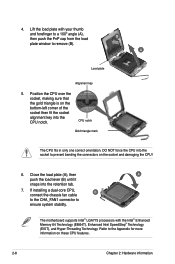
...NOT force the CPU into the socket to ensure system stability. Refer to remove (B). B A Load plate Alignment key 5. If installing a dual-core CPU, connect the chassis fan cable B to the CHA_FAN1 connector to prevent bending the connectors on the bottom‑left corner of the socket then fit the... socket alignment key into the retention tab. 7. CPU notch Gold triangle mark The CPU fits in only one correct orientation. The motherboard supports Intel® LGA775 processors with your thumb and forefinger to a 100º angle (A), then push the PnP cap from the load ...
...NOT force the CPU into the socket to ensure system stability. Refer to remove (B). B A Load plate Alignment key 5. If installing a dual-core CPU, connect the chassis fan cable B to the CHA_FAN1 connector to prevent bending the connectors on the bottom‑left corner of the socket then fit the... socket alignment key into the retention tab. 7. CPU notch Gold triangle mark The CPU fits in only one correct orientation. The motherboard supports Intel® LGA775 processors with your thumb and forefinger to a 100º angle (A), then push the PnP cap from the load ...

User Manual
Page 36
Hardware monitoring errors can occur if you fail to secure the heatsink and fan assembly in a diagonal sequence to plug this connector. 2-10 Chapter 2: Hardware information A A A B B B A 3. 2. Push down two fasteners at a time in B place. DO NOT forget to the connector on the motherboard labeled CPU_FAN. Connect the CPU fan cable to connect the CPU fan connector!
Hardware monitoring errors can occur if you fail to secure the heatsink and fan assembly in a diagonal sequence to plug this connector. 2-10 Chapter 2: Hardware information A A A B B B A 3. 2. Push down two fasteners at a time in B place. DO NOT forget to the connector on the motherboard labeled CPU_FAN. Connect the CPU fan cable to connect the CPU fan connector!

User Manual
Page 39
...fan and motherboard components. then connect the fan cable. • Plug the optional fan cables to the CHA_FAN1 or PWR_FAN connectors on the motherboard. Carefully push down the fan until 4. The photo shows the fan installed it snugly fits the heatsink, and on the motherboard. &#...8226; Ensure the optional fan is installed correctly to prevent damage to the grooved edge of the heatsink. 3. Installing the optional fan with an active CPU cooler will interfere with the airflow and destabilize the system. 1. ASUS P5E Deluxe 2-13 2.3.4 Installing...
...fan and motherboard components. then connect the fan cable. • Plug the optional fan cables to the CHA_FAN1 or PWR_FAN connectors on the motherboard. Carefully push down the fan until 4. The photo shows the fan installed it snugly fits the heatsink, and on the motherboard. &#...8226; Ensure the optional fan is installed correctly to prevent damage to the grooved edge of the heatsink. 3. Installing the optional fan with an active CPU cooler will interfere with the airflow and destabilize the system. 1. ASUS P5E Deluxe 2-13 2.3.4 Installing...

User Manual
Page 50
Refer to a Local Area Network (LAN) through a network hub. Coaxial S/PDIF Out port. This port connects an external audio output device via a coaxial S/PDIF cable. 3. This port allows Gigabit connection to the table below for a PS/2 keyboard. 2. 2.8 Connectors 2.8.1 Rear panel connectors 1. PS/2 keyboard port (...* YELLOW* YELLOW* * Blinking Speed LED OFF OFF ORANGE GREEN Description Soft-off Mode During Power ON/OFF 100 Mbps connection 1 Gbps connection ACT/LINK SPEED LED LED LAN port 64-bit OS LAN port LED indications Activity/Link Speed LED Description OFF YELLOW*...
Refer to a Local Area Network (LAN) through a network hub. Coaxial S/PDIF Out port. This port connects an external audio output device via a coaxial S/PDIF cable. 3. This port allows Gigabit connection to the table below for a PS/2 keyboard. 2. 2.8 Connectors 2.8.1 Rear panel connectors 1. PS/2 keyboard port (...* YELLOW* YELLOW* * Blinking Speed LED OFF OFF ORANGE GREEN Description Soft-off Mode During Power ON/OFF 100 Mbps connection 1 Gbps connection ACT/LINK SPEED LED LED LAN port 64-bit OS LAN port LED indications Activity/Link Speed LED Description OFF YELLOW*...

User Manual
Page 51
...Front Speaker Out. 6. This 6-pin IEEE 1394a port provides high-speed connectivity for connecting USB 2.0 devices. This port connects a microphone. 7. This port connects the rear speakers on the next page for connecting USB 2.0 devices. 11. These 4-pin Universal Serial Bus (USB)...Microphone port (pink). Center/Subwoofer port (orange). 4. This port connects a headphone or a speaker. This port connects the center/subwoofer speakers. 8. This port connects an external audio output device via an optical S/PDIF cable. 14. ASUS P5E Deluxe 2-25 Line Out port (lime). USB 2.0 ports 5 and ...
...Front Speaker Out. 6. This 6-pin IEEE 1394a port provides high-speed connectivity for connecting USB 2.0 devices. This port connects a microphone. 7. This port connects the rear speakers on the next page for connecting USB 2.0 devices. 11. These 4-pin Universal Serial Bus (USB)...Microphone port (pink). Center/Subwoofer port (orange). 4. This port connects a headphone or a speaker. This port connects the center/subwoofer speakers. 8. This port connects an external audio output device via an optical S/PDIF cable. 14. ASUS P5E Deluxe 2-25 Line Out port (lime). USB 2.0 ports 5 and ...

User Manual
Page 52
Insert one end of the cable to this connector, then connect the other end to prevent incorrect cable connection when using a FDD cable with a covered Pin 5. 2-26 Chapter 2: Hardware information 2.8.2 Internal connectors 1. Pin 5 on the connector is for the provided floppy disk drive (FDD) signal cable. Floppy disk drive connector (34-1 pin FLOPPY) This connector is removed to the signal connector at the back of the floppy disk drive.
Insert one end of the cable to this connector, then connect the other end to prevent incorrect cable connection when using a FDD cable with a covered Pin 5. 2-26 Chapter 2: Hardware information 2.8.2 Internal connectors 1. Pin 5 on the connector is for the provided floppy disk drive (FDD) signal cable. Floppy disk drive connector (34-1 pin FLOPPY) This connector is removed to the signal connector at the back of the floppy disk drive.

User Manual
Page 53
Connect the blue connector to the motherboard's IDE connector, then select one of device(s) Master Slave Master Slave Cable connector Black Black Gray Black or gray • Pin 20 on the IDE ... Mode of the following modes to match the covered hole on each Ultra DMA 133/100 signal cable: blue, black, and gray. ASUS P5E Deluxe 2-27 This prevents incorrect insertion when you connect the IDE cable. • Use the 80-conductor IDE cable for the Ultra DMA 133/100 signal cable. IDE connector (40...
Connect the blue connector to the motherboard's IDE connector, then select one of device(s) Master Slave Master Slave Cable connector Black Black Gray Black or gray • Pin 20 on the IDE ... Mode of the following modes to match the covered hole on each Ultra DMA 133/100 signal cable: blue, black, and gray. ASUS P5E Deluxe 2-27 This prevents incorrect insertion when you connect the IDE cable. • Use the 80-conductor IDE cable for the Ultra DMA 133/100 signal cable. IDE connector (40...
User Manual
Page 54
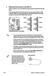
...using Windows® XP or later version. • These connectors are for the Serial ATA signal cables for Serial ATA hard disk drives. Connect the right-angle side of SATA cable to the onboard SATA port to SATA device. right angle side 2-28 Chapter 2: Hardware information See ... 5, use at least three hard disk drives. ICH9R Serial ATA connectors (7-pin SATA1-6) These connectors are set the Configure SATA as item in the motherboard support DVD. 3. If you installed Serial ATA hard disk drives, you can create a RAID 0, RAID 1, RAID 5, RAID 10 configuration with huge...
...using Windows® XP or later version. • These connectors are for the Serial ATA signal cables for Serial ATA hard disk drives. Connect the right-angle side of SATA cable to the onboard SATA port to SATA device. right angle side 2-28 Chapter 2: Hardware information See ... 5, use at least three hard disk drives. ICH9R Serial ATA connectors (7-pin SATA1-6) These connectors are set the Configure SATA as item in the motherboard support DVD. 3. If you installed Serial ATA hard disk drives, you can create a RAID 0, RAID 1, RAID 5, RAID 10 configuration with huge...

User Manual
Page 55
... connector (10-1 pin IE1394_2) This connector is for USB 2.0 ports. Doing so will damage the motherboard! ASUS P5E Deluxe 2-29 4. These USB connectors comply with USB 2.0 specification that supports up to the USB connectors. You can connect the USB cable to ASUS Q-Connector (USB, blue) first, and then install the Q-Connector (USB) to a slot opening at...
... connector (10-1 pin IE1394_2) This connector is for USB 2.0 ports. Doing so will damage the motherboard! ASUS P5E Deluxe 2-29 4. These USB connectors comply with USB 2.0 specification that supports up to the USB connectors. You can connect the USB cable to ASUS Q-Connector (USB, blue) first, and then install the Q-Connector (USB) to a slot opening at...
User Manual
Page 56
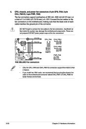
... support the ASUS Q-Fan 2 feature. • If you install two VGA cards, we recommend that you plug the chassis fan cable to the fan connectors on the motherboard, making sure that the black wire of each cable matches the ground pin of 1 A-3.48 A (41.76 W max.) at +12V. Connect the fan ...cables to the motherboard connector labled CHA_FAN1 or CHA_FAN2 for better themal environment. 2-30 Chapter ...
... support the ASUS Q-Fan 2 feature. • If you install two VGA cards, we recommend that you plug the chassis fan cable to the fan connectors on the motherboard, making sure that the black wire of each cable matches the ground pin of 1 A-3.48 A (41.76 W max.) at +12V. Connect the fan ...cables to the motherboard connector labled CHA_FAN1 or CHA_FAN2 for better themal environment. 2-30 Chapter ...

User Manual
Page 57
... using an ASUS HDMI-equipped graphics card, connect the HDMI card to use the chassis intrusion detection feature. 8. 7. If you intend to this connector with a jumper cap. The chassis intrusion sensor or switch sends a high-level signal to this connector when a chassis component is then generated as a chassis intrusion event. ASUS P5E Deluxe 2-31 The...
... using an ASUS HDMI-equipped graphics card, connect the HDMI card to use the chassis intrusion detection feature. 8. 7. If you intend to this connector with a jumper cap. The chassis intrusion sensor or switch sends a high-level signal to this connector when a chassis component is then generated as a chassis intrusion event. ASUS P5E Deluxe 2-31 The...
User Manual
Page 58
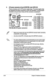
...not forget to fit these connectors in only one orientation. ATX power connectors (24-pin EATXPWR, 8-pin EATX12V) These connectors are designed to connect the 4-pin/8pin EATX12V power plug; The power supply plugs are for details. • The ATX 12 V Specification 2.0-compliant (400W) ...PSU has been tested to support the motherboard power requirements with the following configuration: CPU: Intel® Pentium® Extreme 3.73GHz Memory: 512 MB DDR2 (x4) Graphics card: ASUS EAX1900XT Parallel ATA device: IDE hard disk drive Serial ATA device: SATA...
...not forget to fit these connectors in only one orientation. ATX power connectors (24-pin EATXPWR, 8-pin EATX12V) These connectors are designed to connect the 4-pin/8pin EATX12V power plug; The power supply plugs are for details. • The ATX 12 V Specification 2.0-compliant (400W) ...PSU has been tested to support the motherboard power requirements with the following configuration: CPU: Intel® Pentium® Extreme 3.73GHz Memory: 512 MB DDR2 (x4) Graphics card: ASUS EAX1900XT Parallel ATA device: IDE hard disk drive Serial ATA device: SATA...
User Manual
Page 59
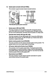
... power LED cable to this connector. Connect the HDD Activity LED cable to this connector. The system power LED lights up or flashes when data is read from or written to hear ... (20-8 pin PANEL) This connector supports several chassis-mounted functions. • System power LED (2-pin PLED) This 2-pin connector is for the system power LED. ASUS P5E Deluxe 2-33 10.
... power LED cable to this connector. Connect the HDD Activity LED cable to this connector. The system power LED lights up or flashes when data is read from or written to hear ... (20-8 pin PANEL) This connector supports several chassis-mounted functions. • System power LED (2-pin PLED) This 2-pin connector is for the system power LED. ASUS P5E Deluxe 2-33 10.

User Manual
Page 60
... are now enabled. Install the ASUS Q-Connector to install the ASUS QConnector. 1. Refer to the instructions below to the system panel connector, making sure the orientation matches the labels on the motherboard. 3. ASUS Q-Connector (system panel) You can use the ASUS Q-Connector to the ASUS Q-Connector. Connect the front panel cables to connect/disconnect chassis front panel cables...
... are now enabled. Install the ASUS Q-Connector to install the ASUS QConnector. 1. Refer to the instructions below to the system panel connector, making sure the orientation matches the labels on the motherboard. 3. ASUS Q-Connector (system panel) You can use the ASUS Q-Connector to the ASUS Q-Connector. Connect the front panel cables to connect/disconnect chassis front panel cables...
User Manual
Page 63
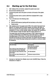
... power 6. The system then runs the power-on the chain) c. If your retailer for the first time 1. At power on . Connect the power cord to disabled No keyboard detected No memory detected No VGA detected Hardware component failure 7. BIOS Beep One short beep One continuous... continuous beep followed by four short beeps Description VGA detected Quick boot set to a power outlet that all the connections, replace the system case cover. 2. ASUS P5E Deluxe 3-1 Monitor b. After making all switches are running, the BIOS beeps (see anything within 30 seconds from the ...
... power 6. The system then runs the power-on the chain) c. If your retailer for the first time 1. At power on . Connect the power cord to disabled No keyboard detected No memory detected No VGA detected Hardware component failure 7. BIOS Beep One short beep One continuous... continuous beep followed by four short beeps Description VGA detected Quick boot set to a power outlet that all the connections, replace the system case cover. 2. ASUS P5E Deluxe 3-1 Monitor b. After making all switches are running, the BIOS beeps (see anything within 30 seconds from the ...
User Manual
Page 67
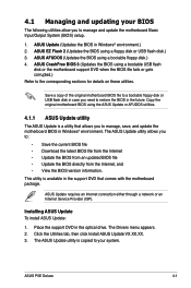
...disk or USB flash disk in case you to manage and update the motherboard Basic Input/Output System (BIOS) setup. 1. Installing ASUS Update To install ASUS Update: 1. Place the support DVD in Windows® environment.) 2. ASUS P5E Deluxe 4-1 4.1 Managing and updating your system. ASUS CrashFree BIOS 3 (Updates the BIOS using a floppy disk or USB ...the BIOS from an updated BIOS file • Update the BIOS directly from the Internet, and • View the BIOS version information. ASUS Update requires an Internet connection either through a network or an Internet Service Provider (ISP).
...disk or USB flash disk in case you to manage and update the motherboard Basic Input/Output System (BIOS) setup. 1. Installing ASUS Update To install ASUS Update: 1. Place the support DVD in Windows® environment.) 2. ASUS P5E Deluxe 4-1 4.1 Managing and updating your system. ASUS CrashFree BIOS 3 (Updates the BIOS using a floppy disk or USB ...the BIOS from an updated BIOS file • Update the BIOS directly from the Internet, and • View the BIOS version information. ASUS Update requires an Internet connection either through a network or an Internet Service Provider (ISP).


