User Guide
Page 1
P5CR-VM Motherboard
P5CR-VM Motherboard
User Guide
Page 3
... to find more information viii Conventions used in this guide ix Typography ix P5CR-VM specifications summary x Chapter 1: Product introduction 1.1 Welcome 1-1 1.2 Package contents 1-1 1.3 Special features 1-2 1.3.1 Product highlights 1-2 1.3.2 Innovative ASUS features 1-4 Chapter 2: Hardware information 2.1 Before you proceed 2-1 2.2 Motherboard overview 2-2 2.2.1 Placement direction 2-2 2.2.2 Screw holes 2-2 2.2.3 Motherboard layout 2-3 2.2.4 Layout contents 2-4 2.3 Central Processing Unit (CPU 2-6 2.3.1 Installing the CPU 2-6 2.3.2 Installing the...
... to find more information viii Conventions used in this guide ix Typography ix P5CR-VM specifications summary x Chapter 1: Product introduction 1.1 Welcome 1-1 1.2 Package contents 1-1 1.3 Special features 1-2 1.3.1 Product highlights 1-2 1.3.2 Innovative ASUS features 1-4 Chapter 2: Hardware information 2.1 Before you proceed 2-1 2.2 Motherboard overview 2-2 2.2.1 Placement direction 2-2 2.2.2 Screw holes 2-2 2.2.3 Motherboard layout 2-3 2.2.4 Layout contents 2-4 2.3 Central Processing Unit (CPU 2-6 2.3.1 Installing the CPU 2-6 2.3.2 Installing the...
User Guide
Page 15
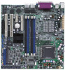
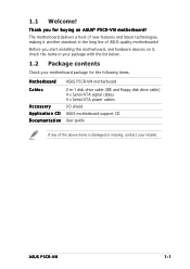
... ATA power cables I/O shield ASUS motherboard support CD User guide If any of ASUS quality motherboards! 1.1 Welcome! The motherboard delivers a host of new features and latest technologies, making it , check the items in your package with the list below. 1.2 Package contents Check your retailer. ASUS P5CR-VM 1-1 Before you for the following items. M o t h e r b o a r d ASUS P5CR-VM motherboard Cables Accessory Application CD Documentation...
... ATA power cables I/O shield ASUS motherboard support CD User guide If any of ASUS quality motherboards! 1.1 Welcome! The motherboard delivers a host of new features and latest technologies, making it , check the items in your package with the list below. 1.2 Package contents Check your retailer. ASUS P5CR-VM 1-1 Before you for the following items. M o t h e r b o a r d ASUS P5CR-VM motherboard Cables Accessory Application CD Documentation...

User Guide
Page 17
...carrying data in packets. See pages 2-23 and 2-28 for details. See page 4-30 for details. USB 2.0 technology The motherboard implements the Universal Serial Bus (USB) 2.0 specification, dramatically increasing the connection speed from the 12 Mbps bandwidth on USB 2.0. ...levels to prevent overheating and damage. Gigabit LAN solution The motherboard comes with a network throughput close to a fast 480 Mbps on USB 1.1 to Gigabit bandwidth. ASUS P5CR-VM 1-3 PCI Express™ interface The motherboard fully supports PCI Express, the latest I/O interconnect technology ...
...carrying data in packets. See pages 2-23 and 2-28 for details. See page 4-30 for details. USB 2.0 technology The motherboard implements the Universal Serial Bus (USB) 2.0 specification, dramatically increasing the connection speed from the 12 Mbps bandwidth on USB 2.0. ...levels to prevent overheating and damage. Gigabit LAN solution The motherboard comes with a network throughput close to a fast 480 Mbps on USB 1.1 to Gigabit bandwidth. ASUS P5CR-VM 1-3 PCI Express™ interface The motherboard fully supports PCI Express, the latest I/O interconnect technology ...
User Guide
Page 20
Chapter summary 2 2.1 Before you proceed 2-1 2.2 Motherboard overview 2-2 2.3 Central Processing Unit (CPU 2-6 2.4 System memory 2-13 2.5 Expansion slots 2-15 2.6 Jumpers 2-18 2.7 Connectors 2-23 ASUS P5CR-VM
Chapter summary 2 2.1 Before you proceed 2-1 2.2 Motherboard overview 2-2 2.3 Central Processing Unit (CPU 2-6 2.4 System memory 2-13 2.5 Expansion slots 2-15 2.6 Jumpers 2-18 2.7 Connectors 2-23 ASUS P5CR-VM
User Guide
Page 21
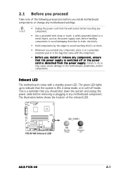
... the power supply case, before removing or plugging in the bag that came with a standby power LED. P5CR-VM P5CR-VM Onboard LED SB_PWR1 ON Standby Power OFF Powered Off ASUS P5CR-VM 2-1 The green LED lights up to indicate that the system is a reminder that you should shut down the... system and unplug the power cable before handling components to avoid damaging them . • Whenever you uninstall any component, place it on a grounded antistatic pad or in any motherboard...
... the power supply case, before removing or plugging in the bag that came with a standby power LED. P5CR-VM P5CR-VM Onboard LED SB_PWR1 ON Standby Power OFF Powered Off ASUS P5CR-VM 2-1 The green LED lights up to indicate that the system is a reminder that you should shut down the... system and unplug the power cable before handling components to avoid damaging them . • Whenever you uninstall any component, place it on a grounded antistatic pad or in any motherboard...
User Guide
Page 22
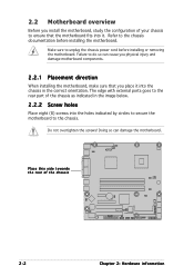
... sure to unplug the chassis power cord before installing the motherboard. Refer to the chassis documentation before installing or removing the motherboard. Place this side towards the rear of the chassis P5CR-VM 2-2 Chapter 2: Hardware information The edge with external ports goes to the rear part of the chassis as indicated in the correct...
... sure to unplug the chassis power cord before installing the motherboard. Refer to the chassis documentation before installing or removing the motherboard. Place this side towards the rear of the chassis P5CR-VM 2-2 Chapter 2: Hardware information The edge with external ports goes to the rear part of the chassis as indicated in the correct...

User Guide
Page 23
25cm (9.8in) 2.2.3 Motherboard layout PS/2KBMS KBPWR1 T: Mouse B: Keyboard USB12 USBPW12 ATXPWR1 PSUSMB1 25cm (9.8in) FM_CPU1 CPU_FAN1 COM1 Intel® E7221 LGA775 ATX12V1 PARALLEL PORT VGA1 LAN1 DDR2 ... CMOS Power CLRTC1 PCIE1 Intel ® ICH6R RECOVERY1 FRNT_FAN1 Broadcom BCM5721 REAR_FAN1 LAN_EN2 Super I/O REAR_FAN2 PCI1 PCI2 COM2 BPSMB1 USBPW56 USBPW78 USBPW34 8Mbit Flash BIOS P5CR-VM TRPWR1 FRNT_FAN2 BMCSOCKET1 FLOPPY1 USB34 USB56 USB78 HDLED1 BMCCONN1 PANEL1 AUX_PANEL1 SB_PWR1 SATA1 SATA2 SATA3 SATA4 ASUS P5CR-VM 2-3
25cm (9.8in) 2.2.3 Motherboard layout PS/2KBMS KBPWR1 T: Mouse B: Keyboard USB12 USBPW12 ATXPWR1 PSUSMB1 25cm (9.8in) FM_CPU1 CPU_FAN1 COM1 Intel® E7221 LGA775 ATX12V1 PARALLEL PORT VGA1 LAN1 DDR2 ... CMOS Power CLRTC1 PCIE1 Intel ® ICH6R RECOVERY1 FRNT_FAN1 Broadcom BCM5721 REAR_FAN1 LAN_EN2 Super I/O REAR_FAN2 PCI1 PCI2 COM2 BPSMB1 USBPW56 USBPW78 USBPW34 8Mbit Flash BIOS P5CR-VM TRPWR1 FRNT_FAN2 BMCSOCKET1 FLOPPY1 USB34 USB56 USB78 HDLED1 BMCCONN1 PANEL1 AUX_PANEL1 SB_PWR1 SATA1 SATA2 SATA3 SATA4 ASUS P5CR-VM 2-3
User Guide
Page 26
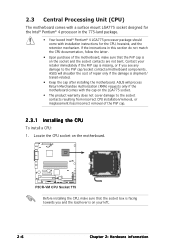
Contact your left. 2-6 Chapter 2: Hardware information P5CR-VM P5CR-VM CPU Socket 775 Before installing the CPU, make sure that the socket box is facing towards you see any damage to the socket contacts resulting ... cap is missing, or if you and the load lever is on the motherboard. ASUS will shoulder the cost of the PnP cap. 2.3.1 Installing the CPU To install a CPU: 1. ASUS will process Return Merchandise Authorization (RMA) requests only if the motherboard comes with installation instructions for the Intel® Pentium® 4 processor in this...
Contact your left. 2-6 Chapter 2: Hardware information P5CR-VM P5CR-VM CPU Socket 775 Before installing the CPU, make sure that the socket box is facing towards you see any damage to the socket contacts resulting ... cap is missing, or if you and the load lever is on the motherboard. ASUS will shoulder the cost of the PnP cap. 2.3.1 Installing the CPU To install a CPU: 1. ASUS will process Return Merchandise Authorization (RMA) requests only if the motherboard comes with installation instructions for the Intel® Pentium® 4 processor in this...

User Guide
Page 29
... Material to the CPU heatsink or CPU before you use ASUS-certified multi-directional heatsink and fan. Orient the heatsink and fan assembly such that you have installed the motherboard to the CPU fan connector. Narrow end of the groove Motherboard hole Fastener Make sure to orient each fastener with the ...make sure that the CPU fan cable is closest to the chassis before you install the heatsink and fan assembly. Place the heatsink on the motherboard. To install the CPU heatsink and fan: 1. Visit the ASUS website for (www.asus.com) for emphasis.) ASUS P5CR-VM 2-9
... Material to the CPU heatsink or CPU before you use ASUS-certified multi-directional heatsink and fan. Orient the heatsink and fan assembly such that you have installed the motherboard to the CPU fan connector. Narrow end of the groove Motherboard hole Fastener Make sure to orient each fastener with the ...make sure that the CPU fan cable is closest to the chassis before you install the heatsink and fan assembly. Place the heatsink on the motherboard. To install the CPU heatsink and fan: 1. Visit the ASUS website for (www.asus.com) for emphasis.) ASUS P5CR-VM 2-9
User Guide
Page 30
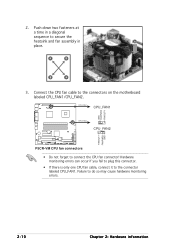
... Chapter 2: Hardware information A B A B B A 3. Failure to the connector labeled CPU_FAN1. CPU_FAN1 CPU_FAN1 GND FANPWR2 FANOUT4 CPU_FAN2 CPU_FAN2 FANOUT7 FANPWR3 GND P5CR-VM P5CR-VM CPU fan connectors • Do not forget to the connectors on the motherboard labeled CPU_FAN1/CPU_FAN2. Connect the CPU fan cable to connect the CPU fan connector! Push down two fasteners at...
... Chapter 2: Hardware information A B A B B A 3. Failure to the connector labeled CPU_FAN1. CPU_FAN1 CPU_FAN1 GND FANPWR2 FANOUT4 CPU_FAN2 CPU_FAN2 FANOUT7 FANPWR3 GND P5CR-VM P5CR-VM CPU fan connectors • Do not forget to the connectors on the motherboard labeled CPU_FAN1/CPU_FAN2. Connect the CPU fan cable to connect the CPU fan connector! Push down two fasteners at...

User Guide
Page 31
Rotate each fastener counterclockwise. 3. Pull up two fasteners at a time in a diagonal sequence to disengage the heatsink B and fan assembly from the connector on the motherboard. 2. 2.3.3 Uninstalling the CPU heatsink and fan To uninstall the CPU heatsink and fan: 1. A B A B B A ASUS P5CR-VM 2-11 Disconnect the CPU fan cable from the A motherboard.
Rotate each fastener counterclockwise. 3. Pull up two fasteners at a time in a diagonal sequence to disengage the heatsink B and fan assembly from the connector on the motherboard. 2. 2.3.3 Uninstalling the CPU heatsink and fan To uninstall the CPU heatsink and fan: 1. A B A B B A ASUS P5CR-VM 2-11 Disconnect the CPU fan cable from the A motherboard.
User Guide
Page 33
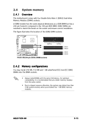
The figure illustrates the location of the DDR2 DIMM sockets: 128 Pins P5CR-VM P5CR-VM 240-pin DDR2 DIMM sockets 112 Pins DIMM_A1 DIMM_A2 DIMM_B1 DIMM_B2 2.4.2 Memory configurations You ... match the break on the socket and ensure correct installation. DDR2 DIMMs are notched to the 184-pin DDR DIMM. ASUS P5CR-VM 2-13 For optimum compatibility, it is recommended that you obtain memory modules from the same vendor. • Due to... Double Data Rate 2 (DDR2) Dual Inline Memory Modules (DIMM) sockets. 2.4 System memory 2.4.1 Overview The motherboard comes with the same CAS latency.
The figure illustrates the location of the DDR2 DIMM sockets: 128 Pins P5CR-VM P5CR-VM 240-pin DDR2 DIMM sockets 112 Pins DIMM_A1 DIMM_A2 DIMM_B1 DIMM_B2 2.4.2 Memory configurations You ... match the break on the socket and ensure correct installation. DDR2 DIMMs are notched to the 184-pin DDR DIMM. ASUS P5CR-VM 2-13 For optimum compatibility, it is recommended that you obtain memory modules from the same vendor. • Due to... Double Data Rate 2 (DDR2) Dual Inline Memory Modules (DIMM) sockets. 2.4 System memory 2.4.1 Overview The motherboard comes with the same CAS latency.

User Guide
Page 35
2.5 Expansion slots In the future, you may cause you physical injury and damage motherboard components. 2.5.1 Installing an expansion card To install an expansion card: 1. Before installing the expansion... you intend to the chassis with it by adjusting the software settings. 1. Remove the system unit cover (if your motherboard is completely seated on BIOS setup. 2. Turn on the next page. 3. Failure to do not need to the ...the slot. 5. Refer to install expansion cards. Install the software drivers for later use . ASUS P5CR-VM 2-15 See Chapter 4 for the card. 2.
2.5 Expansion slots In the future, you may cause you physical injury and damage motherboard components. 2.5.1 Installing an expansion card To install an expansion card: 1. Before installing the expansion... you intend to the chassis with it by adjusting the software settings. 1. Remove the system unit cover (if your motherboard is completely seated on BIOS setup. 2. Turn on the next page. 3. Failure to do not need to the ...the slot. 5. Refer to install expansion cards. Install the software drivers for later use . ASUS P5CR-VM 2-15 See Chapter 4 for the card. 2.
User Guide
Page 37
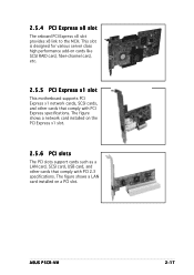
ASUS P5CR-VM 2-17 2.5.4 PCI Express x8 slot The onboard PCI Express x8 slot provides x8 link to the MCH. This slot is designed for various server class high performance add-on cards like SCSI RAID card, fiber-channel card, etc. 2.5.5 PCI Express x1 slot This motherboard supports PCI Express x1 network cards, SCSI cards...
ASUS P5CR-VM 2-17 2.5.4 PCI Express x8 slot The onboard PCI Express x8 slot provides x8 link to the MCH. This slot is designed for various server class high performance add-on cards like SCSI RAID card, fiber-channel card, etc. 2.5.5 PCI Express x1 slot This motherboard supports PCI Express x1 network cards, SCSI cards...

User Guide
Page 45
... the second drive as a slave device by setting its jumper accordingly. P5CR-VM P5CR-VM IDE connector PRI_IDE1 PIN 1 NOTE: Orient the red markings (usually zigzag) on the IDE ribbon cable to match the covered hole on the motherboard, a black connector for an Ultra DMA 100/66 IDE slave device ...(optical drive/hard disk drive), and a gray connector for the primary IDE connector on the Ultra DMA cable connector. ASUS P5CR-VM 2-25 If you install two hard disk drives...
... the second drive as a slave device by setting its jumper accordingly. P5CR-VM P5CR-VM IDE connector PRI_IDE1 PIN 1 NOTE: Orient the red markings (usually zigzag) on the IDE ribbon cable to match the covered hole on the motherboard, a black connector for an Ultra DMA 100/66 IDE slave device ...(optical drive/hard disk drive), and a gray connector for the primary IDE connector on the Ultra DMA cable connector. ASUS P5CR-VM 2-25 If you install two hard disk drives...

User Guide
Page 47
... FANPWR2 GND GND FANPWR2 FANOUT4 CPU_FAN2 REAR_FAN1 REAR_FAN2 P5CR-VM FRNT_FAN1 FRNT_FAN2 REAR_FAN2 REAR_FAN1 Rotation +12V GND FRNT_FAN1 Rotation +12V GND FRNT_FAN2 P5CR-VM Fan connectors Rotation +12V GND Rotation +12V GND ASUS P5CR-VM 2-27 4 . These are not jumpers! Insufficient air flow inside the system may damage the motherboard components. Do not forget to connect the fan...
... FANPWR2 GND GND FANPWR2 FANOUT4 CPU_FAN2 REAR_FAN1 REAR_FAN2 P5CR-VM FRNT_FAN1 FRNT_FAN2 REAR_FAN2 REAR_FAN1 Rotation +12V GND FRNT_FAN1 Rotation +12V GND FRNT_FAN2 P5CR-VM Fan connectors Rotation +12V GND Rotation +12V GND ASUS P5CR-VM 2-27 4 . These are not jumpers! Insufficient air flow inside the system may damage the motherboard components. Do not forget to connect the fan...

User Guide
Page 48
...this LED to light up to 480 Mbps connection speed. The read or write activities of the system chassis. Doing so will damage the motherboard! 2-28 Chapter 2: Hardware information USB+5V USB_4USB_4+ GND NC USB+5V USB_6USB_6+ GND NC USB+5V USB_8USB_8+ GND NC USB+5V ...USB_3USB_3+ USB+5V USB+5V USB_5USB_5+ USB+5V USB+5V USB_7USB_7+ USB+5V USB34 USB56 USB78 P5CR-VM P5CR-VM USB 2.0 connectors Never connect a 1 3 9 4 c a b l e to the hard disk activity LED. HDLED1 1 P5CR-VM P5CR-VM SCSI/SATA card activity LED connector 6 . SCSI_ACTLED+ SCSI_ACTLEDSCSI_ACTLEDSCSI_ACTLED+ 5 .
...this LED to light up to 480 Mbps connection speed. The read or write activities of the system chassis. Doing so will damage the motherboard! 2-28 Chapter 2: Hardware information USB+5V USB_4USB_4+ GND NC USB+5V USB_6USB_6+ GND NC USB+5V USB_8USB_8+ GND NC USB+5V ...USB_3USB_3+ USB+5V USB+5V USB_5USB_5+ USB+5V USB+5V USB_7USB_7+ USB+5V USB34 USB56 USB78 P5CR-VM P5CR-VM USB 2.0 connectors Never connect a 1 3 9 4 c a b l e to the hard disk activity LED. HDLED1 1 P5CR-VM P5CR-VM SCSI/SATA card activity LED connector 6 . SCSI_ACTLED+ SCSI_ACTLEDSCSI_ACTLEDSCSI_ACTLED+ 5 .

User Guide
Page 61
... sections for details on these utilities. c. d. A F o r m a t 3 1 / 2 F l o p p y D i s k window appears. e. ASUS P5CR-VM 4-1 DOS environment a. b. A S U S C r a s h F r e e B I O S 2 (Updates the BIOS using the ASUS Update or AFUDOS utilities. 4.1.1 Creating a bootable floppy disk 1. At the DOS prompt, type format A:/S then press . Copy the original motherboard BIOS using a bootable floppy disk or the motherboard support CD when the BIOS file fails or gets...
... sections for details on these utilities. c. d. A F o r m a t 3 1 / 2 F l o p p y D i s k window appears. e. ASUS P5CR-VM 4-1 DOS environment a. b. A S U S C r a s h F r e e B I O S 2 (Updates the BIOS using the ASUS Update or AFUDOS utilities. 4.1.1 Creating a bootable floppy disk 1. At the DOS prompt, type format A:/S then press . Copy the original motherboard BIOS using a bootable floppy disk or the motherboard support CD when the BIOS file fails or gets...

User Guide
Page 63
... the current BIOS file. You need to the bootable floppy disk you created earlier. 3. Copy the AFUDOS utility (afudos.exe) from the motherboard support CD to type the exact BIOS filename at the prompt type: afudos /i[filename] where [filename] is the latest or the original BIOS...paper. Save the BIOS file to file...... Version 1.19(ASUS V2.07(03.11.24BB)) Copyright (C) 2002 American Megatrends, Inc. Write the BIOS filename on the bootable floppy disk. 3. done Write to a bootable floppy disk. A:\>afudos /iP5CR-VM.ROM ASUS P5CR-VM 4-3 Updating the BIOS file To update the BIOS file ...
... the current BIOS file. You need to the bootable floppy disk you created earlier. 3. Copy the AFUDOS utility (afudos.exe) from the motherboard support CD to type the exact BIOS filename at the prompt type: afudos /i[filename] where [filename] is the latest or the original BIOS...paper. Save the BIOS file to file...... Version 1.19(ASUS V2.07(03.11.24BB)) Copyright (C) 2002 American Megatrends, Inc. Write the BIOS filename on the bootable floppy disk. 3. done Write to a bootable floppy disk. A:\>afudos /iP5CR-VM.ROM ASUS P5CR-VM 4-3 Updating the BIOS file To update the BIOS file ...


