Motherboard DIY Troubleshooting Guide
Page 1
P4V800-X Motherboard
P4V800-X Motherboard

P4V800-X User Manual
Page 1
Motherboard P4V800-X User Guide
Motherboard P4V800-X User Guide
P4V800-X User Manual
Page 3
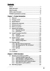
...v Safety information vi About this guide vii ASUS contact information viii P4V800-X specifications summary ix Chapter 1: Product introduction 1.1 Welcome 1-2 1.2 Package contents 1-2 1.3 Special features 1-2 1.4 Motherboard components 1-4 1.5 Motherboard layout 1-7 1.6 Before you proceed 1-8 1.7 Motherboard installation 1-9 1.7.1 Placement direction 1-9 1.7.2 Screw... 1-13 1.10 Expansion slots 1-14 1.10.1 Standard interrupt assignments 1-14 1.10.2 IRQ assignments for this motherboard 1-14 1.10.3 PCI slots 1-15 1.10.4 AGP slot 1-15 1.11 Jumper 1-16 1.12 Connectors ...
...v Safety information vi About this guide vii ASUS contact information viii P4V800-X specifications summary ix Chapter 1: Product introduction 1.1 Welcome 1-2 1.2 Package contents 1-2 1.3 Special features 1-2 1.4 Motherboard components 1-4 1.5 Motherboard layout 1-7 1.6 Before you proceed 1-8 1.7 Motherboard installation 1-9 1.7.1 Placement direction 1-9 1.7.2 Screw... 1-13 1.10 Expansion slots 1-14 1.10.1 Standard interrupt assignments 1-14 1.10.2 IRQ assignments for this motherboard 1-14 1.10.3 PCI slots 1-15 1.10.4 AGP slot 1-15 1.11 Jumper 1-16 1.12 Connectors ...
P4V800-X User Manual
Page 6
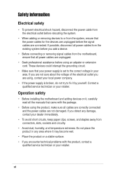
... cables from connectors, slots, sockets and circuitry. • Avoid dust, humidity, and temperature extremes. Operation safety • Before installing the motherboard and adding devices on a stable surface. • If you detect any damage, contact your dealer immediately. • To avoid short circuits..., keep paper clips, screws, and staples away from the motherboard, ensure that came with the product, contact a qualified service technician or your retailer. vi Contact a qualified service technician or your retailer....
... cables from connectors, slots, sockets and circuitry. • Avoid dust, humidity, and temperature extremes. Operation safety • Before installing the motherboard and adding devices on a stable surface. • If you detect any damage, contact your dealer immediately. • To avoid short circuits..., keep paper clips, screws, and staples away from the motherboard, ensure that came with the product, contact a qualified service technician or your retailer. vi Contact a qualified service technician or your retailer....
P4V800-X User Manual
Page 11
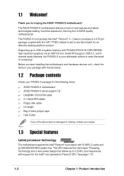
Chapter 1 This chapter describes the features of the layout, jumper settings, and connectors. Product introduction It includes brief descriptions of the motherboard components, and illustrations of the P4V800-X motherboard.
Chapter 1 This chapter describes the features of the layout, jumper settings, and connectors. Product introduction It includes brief descriptions of the motherboard components, and illustrations of the P4V800-X motherboard.
P4V800-X User Manual
Page 12
... hardware devices on it another standout in your package with the list below. 1.2 Package contents Check your P4V800-X package for the following items. ASUS P4V800-X motherboard ASUS P4V800-X series support CD UltraDMA 133/100/66 cable 2 x Serial ATA cables Floppy disk cable I/O shield Bag of extra jumper caps User Guide If any of ...
... hardware devices on it another standout in your package with the list below. 1.2 Package contents Check your P4V800-X package for the following items. ASUS P4V800-X motherboard ASUS P4V800-X series support CD UltraDMA 133/100/66 cable 2 x Serial ATA cables Floppy disk cable I/O shield Bag of extra jumper caps User Guide If any of ...
P4V800-X User Manual
Page 13
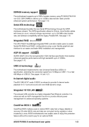
...or when invaded by a virus. See page 1-18. AGP 8X support AGP8X (AGP 3.0) is a highly integrated Fast Ethernet controller. ASUS P4V800-X motherboard user guide 1-3 See page 1-12. Integrated 10/100 LAN The onboard LAN controller is the next generation VGA interface specification that enables...See pages 1-15. The SATA specification allows for an optional ROM. Serial ATA technology The motherboard bundles the new Serial ATA technology through the SATA interfaces onboard. ASUS motherboards now enable users to enjoy this protection feature without the need to 150 MB/s data ...
...or when invaded by a virus. See page 1-18. AGP 8X support AGP8X (AGP 3.0) is a highly integrated Fast Ethernet controller. ASUS P4V800-X motherboard user guide 1-3 See page 1-12. Integrated 10/100 LAN The onboard LAN controller is the next generation VGA interface specification that enables...See pages 1-15. The SATA specification allows for an optional ROM. Serial ATA technology The motherboard bundles the new Serial ATA technology through the SATA interfaces onboard. ASUS motherboards now enable users to enjoy this protection feature without the need to 150 MB/s data ...
P4V800-X User Manual
Page 14
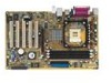
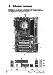
Refer to facilitate the installation and future upgrades. 1.4 Motherboard components Before you install the motherboard, learn about its major components and available features to the succeeding pages for the component descriptions. 1 23 4 5 6 7 16 8 15 9 14 10 13 12 11 17 18 19 20 21 22 27 26 1-4 25 24 23 Chapter 1: Product introduction
Refer to facilitate the installation and future upgrades. 1.4 Motherboard components Before you install the motherboard, learn about its major components and available features to the succeeding pages for the component descriptions. 1 23 4 5 6 7 16 8 15 9 14 10 13 12 11 17 18 19 20 21 22 27 26 1-4 25 24 23 Chapter 1: Product introduction
P4V800-X User Manual
Page 15
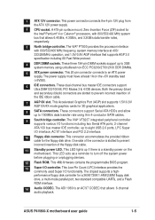
...174; Pentium® 4 or Celeron® processors, with 800/533/400 MHz frequency, system memory interface at least 1A on the motherboard. This LED acts as a reminder to an ATX power supply. These three 184-pin DIMM sockets support up to eight USB 2.0 ports...graphical applications. 8 SATA connectors. This Low Pin Count (LPC) interface provides the commonly used Super I/O functionality. 1 ATX 12V connector. ASUS P4V800-X motherboard user guide 1-5 The ADI 1980 is slotted to prevent incorrect insertion of the floppy disk cable. 11 Standby power LED. This LED lights...
...174; Pentium® 4 or Celeron® processors, with 800/533/400 MHz frequency, system memory interface at least 1A on the motherboard. This LED acts as a reminder to an ATX power supply. These three 184-pin DIMM sockets support up to eight USB 2.0 ports...graphical applications. 8 SATA connectors. This Low Pin Count (LPC) interface provides the commonly used Super I/O functionality. 1 ATX 12V connector. ASUS P4V800-X motherboard user guide 1-5 The ADI 1980 is slotted to prevent incorrect insertion of the floppy disk cable. 11 Standby power LED. This LED lights...
P4V800-X User Manual
Page 17
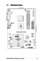
ATX Power Connector SEC_IDE1 PRI_IDE1 30.5cm (12.0in) 1.5 Motherboard layout PS/2KBMS T: Mouse B: Keyboard SPDIF1 ATX12V1 19.3cm 7.6in) CPU_FAN1 DDR DIMM1 (64/72 bit,184-pin module) DDR DIMM2 (64/72 bit,184-... Out Below:Mic In VIA PT800 Chip REALTEK FP_AUDIO CD AUX Audio Codec Super I/O 4Mbit ROM Accelerated Graphics Port (AGP) SATA1 PCI1 ® PCI2 P4V800-X PCI3 PCI4 SB_PWR1 PCI5 GAME1 VIA VT8237 Chipset SATA2 CR2032 3V Lithium Cell CMOS Power CHASSIS1 CLRTC1 USBPW78 USBPW56 USB78 USB56 CHA_FAN1 PANEL1 FLOPPY ASUS P4V800-X motherboard user guide 1-7
ATX Power Connector SEC_IDE1 PRI_IDE1 30.5cm (12.0in) 1.5 Motherboard layout PS/2KBMS T: Mouse B: Keyboard SPDIF1 ATX12V1 19.3cm 7.6in) CPU_FAN1 DDR DIMM1 (64/72 bit,184-pin module) DDR DIMM2 (64/72 bit,184-... Out Below:Mic In VIA PT800 Chip REALTEK FP_AUDIO CD AUX Audio Codec Super I/O 4Mbit ROM Accelerated Graphics Port (AGP) SATA1 PCI1 ® PCI2 P4V800-X PCI3 PCI4 SB_PWR1 PCI5 GAME1 VIA VT8237 Chipset SATA2 CR2032 3V Lithium Cell CMOS Power CHASSIS1 CLRTC1 USBPW78 USBPW56 USB78 USB56 CHA_FAN1 PANEL1 FLOPPY ASUS P4V800-X motherboard user guide 1-7
P4V800-X User Manual
Page 18
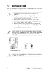
...the power cable before handling components to avoid damaging them . 4. Failure to do so may cause severe damage to your AGP card or motherboard. 1-8 Chapter 1: Product introduction P4V800-X P4V800-X Onboard LED SB_PWR1 ON Standby Power OFF Powered Off Install only 0.8V and 1.5V AGP cards on them due to static electricity. 3.... case, before removing or plugging in the bag that you uninstall any component, place it on a grounded antistatic pad or in any motherboard settings. 1. Use a grounded wrist strap or touch a safely grounded object or to avoid touching the ICs on this...
...the power cable before handling components to avoid damaging them . 4. Failure to do so may cause severe damage to your AGP card or motherboard. 1-8 Chapter 1: Product introduction P4V800-X P4V800-X Onboard LED SB_PWR1 ON Standby Power OFF Powered Off Install only 0.8V and 1.5V AGP cards on them due to static electricity. 3.... case, before removing or plugging in the bag that you uninstall any component, place it on a grounded antistatic pad or in any motherboard settings. 1. Use a grounded wrist strap or touch a safely grounded object or to avoid touching the ICs on this...
P4V800-X User Manual
Page 19
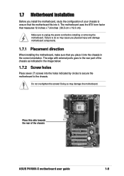
... unplug the power cord before installing or removing the motherboard. Failure to do so may damage the motherboard. Doing so may cause you physical injury and damage motherboard components. 1.7.1 Placement direction When installing the motherboard, make sure that you install the motherboard, study the configuration of the chassis ASUS P4V800-X motherboard user guide 1-9 Do not overtighten the screws...
... unplug the power cord before installing or removing the motherboard. Failure to do so may damage the motherboard. Doing so may cause you physical injury and damage motherboard components. 1.7.1 Placement direction When installing the motherboard, make sure that you install the motherboard, study the configuration of the chassis ASUS P4V800-X motherboard user guide 1-9 Do not overtighten the screws...
P4V800-X User Manual
Page 20
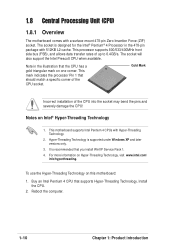
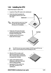
... introduction The socket will also support the Intel Prescott CPU when available. Notes on one corner. For more information on this motherboard: 1. Hyper-Threading Technology is designed for the Intel® Pentium® 4 Processor in the illustration that supports Hyper-Threading...mark indicates the processor Pin 1 that you install WinXP Service Pack 1. 4. 1.8 Central Processing Unit (CPU) 1.8.1 Overview The motherboard comes with Hyper-Threading Technology. 2. Buy an Intel Pentium 4 CPU that the CPU has a gold triangular mark on Intel® Hyper-Threading ...
... introduction The socket will also support the Intel Prescott CPU when available. Notes on one corner. For more information on this motherboard: 1. Hyper-Threading Technology is designed for the Intel® Pentium® 4 Processor in the illustration that supports Hyper-Threading...mark indicates the processor Pin 1 that you install WinXP Service Pack 1. 4. 1.8 Central Processing Unit (CPU) 1.8.1 Overview The motherboard comes with Hyper-Threading Technology. 2. Buy an Intel Pentium 4 CPU that the CPU has a gold triangular mark on Intel® Hyper-Threading ...
P4V800-X User Manual
Page 21
... such that came with the heatsink package. 7. When the CPU is lifted up to secure the CPU. Locate the 478-pin ZIF socket on the motherboard. ASUS P4V800-X motherboard user guide 1-11 Socket Lever Make sure that the socket lever is in one correct orientation. Gold Mark The CPU fits only in place, push...
... such that came with the heatsink package. 7. When the CPU is lifted up to secure the CPU. Locate the 478-pin ZIF socket on the motherboard. ASUS P4V800-X motherboard user guide 1-11 Socket Lever Make sure that the socket lever is in one correct orientation. Gold Mark The CPU fits only in place, push...
P4V800-X User Manual
Page 22
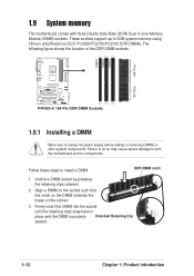
... up to unplug the power supply before adding or removing DIMMs or other system components. DIMM1 DIMM2 DIMM3 104 Pins 80 Pins ® P4V800-X P4V800-X 184-Pin DDR DIMM Sockets 1.9.1 Installing a DIMM Make sure to 3GB system memory using 184-pin unbuffered non-ECC PC3200/PC2700/PC2100 DDR ...socket such that the notch on the DIMM matches the break on the socket. 3. Follow these steps to both the motherboard and the components. DDR DIMM notch 1. 1.9 System memory The motherboard comes with three Double Data Rate (DDR) Dual In-Line Memory Module (DIMM) sockets. Unlock a DIMM socket by...
... up to unplug the power supply before adding or removing DIMMs or other system components. DIMM1 DIMM2 DIMM3 104 Pins 80 Pins ® P4V800-X P4V800-X 184-Pin DDR DIMM Sockets 1.9.1 Installing a DIMM Make sure to 3GB system memory using 184-pin unbuffered non-ECC PC3200/PC2700/PC2100 DDR ...socket such that the notch on the DIMM matches the break on the socket. 3. Follow these steps to both the motherboard and the components. DDR DIMM notch 1. 1.9 System memory The motherboard comes with three Double Data Rate (DDR) Dual In-Line Memory Module (DIMM) sockets. Unlock a DIMM socket by...
P4V800-X User Manual
Page 23
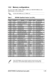
... K4H560838D-TCCC CENTURY DS K4H560838D-TCCC Elixir SS N2DS25680BT-5T Elixir DS N2DS25680BT-5T Obtain DDR DIMMs only from ASUS qualified vendors for the latest QVL. ASUS P4V800-X motherboard user guide 1-13 Visit the ASUS website (www.asus.com) for better system performance. 1.9.2 Memory configurations You may install 64MB, 128MB, 256MB, 512MB, and 1GB DDR DIMMs...
... K4H560838D-TCCC CENTURY DS K4H560838D-TCCC Elixir SS N2DS25680BT-5T Elixir DS N2DS25680BT-5T Obtain DDR DIMMs only from ASUS qualified vendors for the latest QVL. ASUS P4V800-X motherboard user guide 1-13 Visit the ASUS website (www.asus.com) for better system performance. 1.9.2 Memory configurations You may install 64MB, 128MB, 256MB, 512MB, and 1GB DDR DIMMs...
P4V800-X User Manual
Page 24
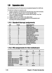
...to the card. Onboard USB controller HC1 shared - - - Assign an IRQ to the tables below. 4. shared - - shared - - See Chapter 2 for this motherboard A B C D PCI slot 1 - PCI slot 5 - Onboard USB 2.0 controller - - shared - AGP slot shared - - - To install and configure an ...3 System CMOS/Real Time Clock 9* 4 ACPI Mode when used PCI slot 4 shared - - - 1.10 Expansion slots The motherboard has five PCI slots and one Accelerated Graphics Port (AGP) slot. Install an expansion card following the instructions that came with the...
...to the card. Onboard USB controller HC1 shared - - - Assign an IRQ to the tables below. 4. shared - - shared - - See Chapter 2 for this motherboard A B C D PCI slot 1 - PCI slot 5 - Onboard USB 2.0 controller - - shared - AGP slot shared - - - To install and configure an ...3 System CMOS/Real Time Clock 9* 4 ACPI Mode when used PCI slot 4 shared - - - 1.10 Expansion slots The motherboard has five PCI slots and one Accelerated Graphics Port (AGP) slot. Install an expansion card following the instructions that came with the...
P4V800-X User Manual
Page 25
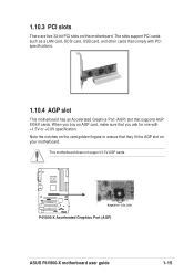
... Graphics Port (AGP) slot that supports AGP 8X/4X cards. When you ask for 1.5v, 0.8v P4V800-X Accelerated Graphics Port (AGP) ASUS P4V800-X motherboard user guide 1-15 Note the notches on this motherboard. 1.10.3 PCI slots There are five 32-bit PCI slots on the card golden fingers to ensure that... you buy an AGP card, make sure that they fit the AGP slot on your motherboard. The slots support...
... Graphics Port (AGP) slot that supports AGP 8X/4X cards. When you ask for 1.5v, 0.8v P4V800-X Accelerated Graphics Port (AGP) ASUS P4V800-X motherboard user guide 1-15 Note the notches on this motherboard. 1.10.3 PCI slots There are five 32-bit PCI slots on the card golden fingers to ensure that... you buy an AGP card, make sure that they fit the AGP slot on your motherboard. The slots support...
P4V800-X User Manual
Page 27
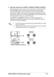
... not all computers have the appropriate power supply to the front USB ports. 1. USBPW12 USBPW34 12 23 ® P4V800-X +5V (Default) +5VSB USBPW78 USBPW56 12 23 +5V P4V800-X USB Device Wake Up (Default) +5VSB ASUS P4V800-X motherboard user guide 1-17 The USBPW12 and USBPW34 jumpers are for each USB port. 2. USB device wake-up (3-pin...
... not all computers have the appropriate power supply to the front USB ports. 1. USBPW12 USBPW34 12 23 ® P4V800-X +5V (Default) +5VSB USBPW78 USBPW56 12 23 +5V P4V800-X USB Device Wake Up (Default) +5VSB ASUS P4V800-X motherboard user guide 1-17 The USBPW12 and USBPW34 jumpers are for each USB port. 2. USB device wake-up (3-pin...
P4V800-X User Manual
Page 28
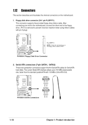
... connectors (7-pin SATA1, SATA2) These next generation connectors support the thin Serial ATA cables for Serial ATA hard disks. After connecting one end to the motherboard, connect the other end to the floppy drive. (Pin 5 is removed to 150 MB/s data transfer rate, faster than the standard parallel ATA with pin... connector supports the provided floppy drive ribbon cable. 1.12 Connectors This section describes and illustrates the internal connectors on the floppy ribbon cable to PIN 1. P4V800-X PIN 1 FLOPPY1 NOTE: Orient the red markings on the motherboard. 1.
... connectors (7-pin SATA1, SATA2) These next generation connectors support the thin Serial ATA cables for Serial ATA hard disks. After connecting one end to the motherboard, connect the other end to the floppy drive. (Pin 5 is removed to 150 MB/s data transfer rate, faster than the standard parallel ATA with pin... connector supports the provided floppy drive ribbon cable. 1.12 Connectors This section describes and illustrates the internal connectors on the floppy ribbon cable to PIN 1. P4V800-X PIN 1 FLOPPY1 NOTE: Orient the red markings on the motherboard. 1.


