
Motherboard DIY Troubleshooting Guide
Page 59
TRPWR Ground TRPWR P4T533 ® P4T533 Power Supply Thermal Connector Keyboard Lock Speaker Power LED Connector +5 V PLED Keylock Ground +5V Ground Ground Speaker +5 V MLED ExtSMI# Ground PWR Ground Reset Ground P4T533 ® P4T533 System Panel Connectors Message LED SMI Lead Reset SW ATX Power Switch* * Requires an ATX power supply. 43
TRPWR Ground TRPWR P4T533 ® P4T533 Power Supply Thermal Connector Keyboard Lock Speaker Power LED Connector +5 V PLED Keylock Ground +5V Ground Ground Speaker +5 V MLED ExtSMI# Ground PWR Ground Reset Ground P4T533 ® P4T533 System Panel Connectors Message LED SMI Lead Reset SW ATX Power Switch* * Requires an ATX power supply. 43
P4T533 User Manual
Page 18
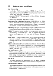
...; Adjustable Vcore Voltage (See page 27 and 66.) Temperature, Fan and Voltage Monitoring: ASUS ASIC and the CPU's internal thermal diode monitors temperature to prevent overheating. USB2.0: The latest connection standard for RPM and failure. Pressing the power switch for more Energy Saving Features to soft-off automatically when the system is available...
...; Adjustable Vcore Voltage (See page 27 and 66.) Temperature, Fan and Voltage Monitoring: ASUS ASIC and the CPU's internal thermal diode monitors temperature to prevent overheating. USB2.0: The latest connection standard for RPM and failure. Pressing the power switch for more Energy Saving Features to soft-off automatically when the system is available...

P4T533 User Manual
Page 23
... Graphics Slot Motherboard Settings (Switches and Jumpers) 1) JEN p. 22 JumperFree Mode Setting (Disable/Enable) 2) DSW1 p. 23 CPU External Frequency Selection (Switches 1-5) 3) DSW p. 24 CPU Frequency Multiple Setting (Switches 1-4) 4) USB_EN p. 25...Power Connectors (20-pin, 4-pin, 4-pin ) 12V EZ_PLUG, ATX12V 14) SMB p. 38 SMBus Connector (6-1 pin) 15) USB11_34 p. 39 USB Headers (10-1 pin) 16) USB20_34 p. 39 USB 2.0 Headers (10-1 pin) 17) CD, AUX, MODEM p. 40 Internal Audio Connectors (Three 4-1 pin) (optional) 18) CHASSIS p. 40 Chassis Open Alarm Lead (4-1 pin) ASUS P4T533...
... Graphics Slot Motherboard Settings (Switches and Jumpers) 1) JEN p. 22 JumperFree Mode Setting (Disable/Enable) 2) DSW1 p. 23 CPU External Frequency Selection (Switches 1-5) 3) DSW p. 24 CPU Frequency Multiple Setting (Switches 1-4) 4) USB_EN p. 25...Power Connectors (20-pin, 4-pin, 4-pin ) 12V EZ_PLUG, ATX12V 14) SMB p. 38 SMBus Connector (6-1 pin) 15) USB11_34 p. 39 USB Headers (10-1 pin) 16) USB20_34 p. 39 USB 2.0 Headers (10-1 pin) 17) CD, AUX, MODEM p. 40 Internal Audio Connectors (Three 4-1 pin) (optional) 18) CHASSIS p. 40 Chassis Open Alarm Lead (4-1 pin) ASUS P4T533...
P4T533 User Manual
Page 24
...41 Smart Card Reader connector (14-1 pin) (optional) 20) FP_LO_SWL, FP_LO_SWR p. 41 Line-out Selector Jumpers (Two 2 pin) 21) AFPANEL p. 42 ASUS iPanel / Infrared Connector (24-1 pin) 22) LINE_IN p. 43 Front Panel Audio Line In Header (5 pin) 23) AAPANEL p. 43 Front Panel Audio ...Message LED Lead (2 pin) 31) SMI p. 46 System Management Interrupt Lead (2 pin) 32) PWRSW p. 46 ATX Power Switch / Soft-Off Switch Lead (2 pin) 33) RESET p. 46 Reset Switch Lead (2-pin) 2.3 Before you proceed Take note of the following precautions before you install or remove any component, ensure that...
...41 Smart Card Reader connector (14-1 pin) (optional) 20) FP_LO_SWL, FP_LO_SWR p. 41 Line-out Selector Jumpers (Two 2 pin) 21) AFPANEL p. 42 ASUS iPanel / Infrared Connector (24-1 pin) 22) LINE_IN p. 43 Front Panel Audio Line In Header (5 pin) 23) AAPANEL p. 43 Front Panel Audio ...Message LED Lead (2 pin) 31) SMI p. 46 System Management Interrupt Lead (2 pin) 32) PWRSW p. 46 ATX Power Switch / Soft-Off Switch Lead (2 pin) 33) RESET p. 46 Reset Switch Lead (2-pin) 2.3 Before you proceed Take note of the following precautions before you install or remove any component, ensure that...
P4T533 User Manual
Page 40
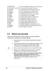
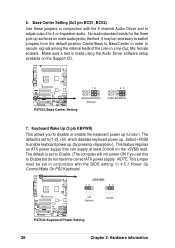
... allows you set to reroute signals among the internal leads of the Line-In, Line-Out, Mic female sockets. KBPWR 12 23 P4T533 ® +5V (Default) P4T533 Keyboard Power Setting +5VSB 26 Chapter 2: Hardware information therfore, it may be set in conjunction with the 6 channel Audio Driver and to enable...for the three pick-up . NOTE: This jumper must be necessary to switch jumpers from the default position Center/Bass to Bass/Center in 4.5.1 Power Up Control:Wake On PS2 Keyboard. This feature requires an ATX power supply that can supply at least 300mA on the +5VSB lead. Bass ...
... allows you set to reroute signals among the internal leads of the Line-In, Line-Out, Mic female sockets. KBPWR 12 23 P4T533 ® +5V (Default) P4T533 Keyboard Power Setting +5VSB 26 Chapter 2: Hardware information therfore, it may be set in conjunction with the 6 channel Audio Driver and to enable...for the three pick-up . NOTE: This jumper must be necessary to switch jumpers from the default position Center/Bass to Bass/Center in 4.5.1 Power Up Control:Wake On PS2 Keyboard. This feature requires an ATX power supply that can supply at least 300mA on the +5VSB lead. Bass ...
P4T533 User Manual
Page 60
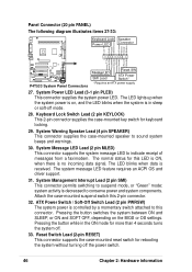
...ON, when there is in the ON mode for this 2-pin connector. 32. ATX Power Switch / Soft-Off Switch Lead (2 pin PWRSW) The system power is decreased to this connector. Pressing the button switches the system between ON and SLEEP, or ON and SOFT OFF, depending on , ...illustrates items 27-33: Keyboard Lock Speaker Power LED Connector +5 V PLED Keylock Ground +5V Ground Ground Speaker +5 V MLED ExtSMI# Ground PWR Ground Reset Ground P4T533 ® P4T533 System Panel Connectors Message LED SMI Lead Reset SW ATX Power Switch* * Requires an ATX power supply. 27. The LED blinks when ...
...ON, when there is in the ON mode for this 2-pin connector. 32. ATX Power Switch / Soft-Off Switch Lead (2 pin PWRSW) The system power is decreased to this connector. Pressing the button switches the system between ON and SLEEP, or ON and SOFT OFF, depending on , ...illustrates items 27-33: Keyboard Lock Speaker Power LED Connector +5 V PLED Keylock Ground +5V Ground Ground Speaker +5 V MLED ExtSMI# Ground PWR Ground Reset Ground P4T533 ® P4T533 System Panel Connectors Message LED SMI Lead Reset SW ATX Power Switch* * Requires an ATX power supply. 27. The LED blinks when ...
P4T533 User Manual
Page 63
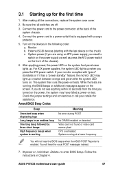
...the time you need to enter BIOS Setup. At power on, hold down to switch on the power supply as well as press the ATX power switch on the system front panel case lights up when you press the ATX power switch. Be sure that is working Meaning No error during.... 2. Check the jumper settings and connections or call your monitor complies with "green" standards or if it has a "power standby" feature, the monitor LED may have failed a power-on the chain) c. After making all switches are running at the back of the chassis). 6. ASUS P4T533 motherboard user guide 47
...the time you need to enter BIOS Setup. At power on, hold down to switch on the power supply as well as press the ATX power switch on the system front panel case lights up when you press the ATX power switch. Be sure that is working Meaning No error during.... 2. Check the jumper settings and connections or call your monitor complies with "green" standards or if it has a "power standby" feature, the monitor LED may have failed a power-on the chain) c. After making all switches are running at the back of the chassis). 6. ASUS P4T533 motherboard user guide 47

P4T533 User Manual
Page 66
For ATX power supplies, you use Windows 95/98/2000/XP, click the Start button, click Shut Down, then click the OK button to shut down the system before switching off the power. The power supply should turn off your computer" does not appear when shutting down with ATX power supplies. 50 Chapter 3: Powering up 3.3 Powering off the computer You must first exit the operating system and shut down the computer. If you can now safely turn off after exiting or shutting down . The message "You can press the ATX power switch after Windows shuts down the operating system.
For ATX power supplies, you use Windows 95/98/2000/XP, click the Start button, click Shut Down, then click the OK button to shut down the system before switching off the power. The power supply should turn off your computer" does not appear when shutting down with ATX power supplies. 50 Chapter 3: Powering up 3.3 Powering off the computer You must first exit the operating system and shut down the computer. If you can now safely turn off after exiting or shutting down . The message "You can press the ATX power switch after Windows shuts down the operating system.
P4T533 User Manual
Page 93
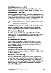
... Off ] This field determines when to -RAM feature. Use this for the above field. [V/H SYNC+Blank] blanks the screen and turns off ], the ATX switch can be used as set to [Soft off vertical and horizontal scanning. Configuration options: [Disabled] [1~2 Min] [2~3 Min] [4~5 min] [8~9 Min] [20 Min...: [Always On] [Suspend -> Off] Video Off Method [DPMS OFF] This field defines the video off ] [Suspend] ASUS P4T533 motherboard user guide 75 The Display Power Management System (DPMS) feature allows the BIOS to provide more than 720mA current. Even if installed, your screen saver does not...
... Off ] This field determines when to -RAM feature. Use this for the above field. [V/H SYNC+Blank] blanks the screen and turns off ], the ATX switch can be used as set to [Soft off vertical and horizontal scanning. Configuration options: [Disabled] [1~2 Min] [2~3 Min] [4~5 min] [8~9 Min] [20 Min...: [Always On] [Suspend -> Off] Video Off Method [DPMS OFF] This field defines the video off ] [Suspend] ASUS P4T533 motherboard user guide 75 The Display Power Management System (DPMS) feature allows the BIOS to provide more than 720mA current. Even if installed, your screen saver does not...
P4T533 User Manual
Page 133
Index Symbols 3Deep Color Tuner Using 92 A Accelerated Graphics Port 21 ASUS MyLogo™ 98 ASUS PC Probe Using 86 ASUS Update Using 91 ATAPI CD-ROM 78 Automatic Power Up 77 B BIOS Advanced Menu 66 Beep Codes 47 Boot Menu 78 Boot Sequence 78 Exit Menu 80 Language 65...interfaces S/PDIF 6 DIP Switches 22 E Expansion card installation 19 IRQ assigments 20 Expansion slots 19 F Floppy 3 Mode 59 Floppy Disk Drive Connector 9 H Hard Disk Drives (HDDs) CHS Capacity 62 Cylinders 62 Heads 62 LBA Capacity 62 Primary/Secondary Master 60 Primary/Secondary Slave 60 ASUS P4T533 motherboard user guide 111...
Index Symbols 3Deep Color Tuner Using 92 A Accelerated Graphics Port 21 ASUS MyLogo™ 98 ASUS PC Probe Using 86 ASUS Update Using 91 ATAPI CD-ROM 78 Automatic Power Up 77 B BIOS Advanced Menu 66 Beep Codes 47 Boot Menu 78 Boot Sequence 78 Exit Menu 80 Language 65...interfaces S/PDIF 6 DIP Switches 22 E Expansion card installation 19 IRQ assigments 20 Expansion slots 19 F Floppy 3 Mode 59 Floppy Disk Drive Connector 9 H Hard Disk Drives (HDDs) CHS Capacity 62 Cylinders 62 Heads 62 LBA Capacity 62 Primary/Secondary Master 60 Primary/Secondary Slave 60 ASUS P4T533 motherboard user guide 111...


