
Motherboard DIY Troubleshooting Guide
Page 52
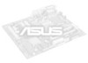
ATXPWR EZ_PLUG +3.3VDC -12.0VDC +3.3VDC +3.3VDC NC GND GND GND GND +12V PS_ON# +5.0VDC GND GND GND +5.0VDC GND -5.0VDC GND PWR_OK ATX12V P4T533 +5.0VDC +5VSB ® +5.0VDC +12.0VDC GND GND +12V DC +12V DC P4T533 ATX & Auxiliary Power Connectors FLOATING SMBCLK Ground SMBDATA +3V P4T533 ® P4T533 SMBus Connector 36 SMB 1
ATXPWR EZ_PLUG +3.3VDC -12.0VDC +3.3VDC +3.3VDC NC GND GND GND GND +12V PS_ON# +5.0VDC GND GND GND +5.0VDC GND -5.0VDC GND PWR_OK ATX12V P4T533 +5.0VDC +5VSB ® +5.0VDC +12.0VDC GND GND +12V DC +12V DC P4T533 ATX & Auxiliary Power Connectors FLOATING SMBCLK Ground SMBDATA +3V P4T533 ® P4T533 SMBus Connector 36 SMB 1

Motherboard DIY Troubleshooting Guide
Page 59
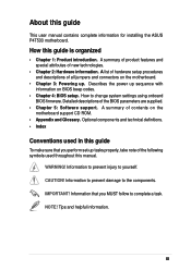
TRPWR Ground TRPWR P4T533 ® P4T533 Power Supply Thermal Connector Keyboard Lock Speaker Power LED Connector +5 V PLED Keylock Ground +5V Ground Ground Speaker +5 V MLED ExtSMI# Ground PWR Ground Reset Ground P4T533 ® P4T533 System Panel Connectors Message LED SMI Lead Reset SW ATX Power Switch* * Requires an ATX power supply. 43
TRPWR Ground TRPWR P4T533 ® P4T533 Power Supply Thermal Connector Keyboard Lock Speaker Power LED Connector +5 V PLED Keylock Ground +5V Ground Ground Speaker +5 V MLED ExtSMI# Ground PWR Ground Reset Ground P4T533 ® P4T533 System Panel Connectors Message LED SMI Lead Reset SW ATX Power Switch* * Requires an ATX power supply. 43
P4T533 User Manual
Page 3
... note of all jumpers and connectors on the motherboard. • Chapter 3: Powering up sequence with information on the motherboard support CD ROM. • Appendix and Glossary. NOTE! Describes the power up . Detailed descriptions of new technologies. • Chapter 2: Hardware information.... change system settings using onboard BIOS firmware. How this guide This user manual contains complete information for installing the ASUS P4T533 motherboard. How to complete a task. WARNING! Tips and helpful information. CAUTION! Optional components and technical definitions. •...
... note of all jumpers and connectors on the motherboard. • Chapter 3: Powering up sequence with information on the motherboard support CD ROM. • Appendix and Glossary. NOTE! Describes the power up . Detailed descriptions of new technologies. • Chapter 2: Hardware information.... change system settings using onboard BIOS firmware. How this guide This user manual contains complete information for installing the ASUS P4T533 motherboard. How to complete a task. WARNING! Tips and helpful information. CAUTION! Optional components and technical definitions. •...
P4T533 User Manual
Page 5
...Main menu 59 4.4 Advanced Menu 66 4.5 Power Menu 74 4.6 Boot Menu 79 4.7 Exit Menu 81 Chapter 5: Software support 83 5.1 Install an operating system 83 5.2 Support CD information 83 5.3 P4T533 Motherboard Support CD 84 5.4 ASUS PC Probe 86 5.5 ASUS Live Update 91 5.6 3Deep Color Tuner ...92 5.7 Winbond Voice Editor 94 5.8 ASUS MyLogo2 98 ™ ...5.9 Multi-Channel Audio Feature Setup 100 5.10 Using...
...Main menu 59 4.4 Advanced Menu 66 4.5 Power Menu 74 4.6 Boot Menu 79 4.7 Exit Menu 81 Chapter 5: Software support 83 5.1 Install an operating system 83 5.2 Support CD information 83 5.3 P4T533 Motherboard Support CD 84 5.4 ASUS PC Probe 86 5.5 ASUS Live Update 91 5.6 3Deep Color Tuner ...92 5.7 Winbond Voice Editor 94 5.8 ASUS MyLogo2 98 ™ ...5.9 Multi-Channel Audio Feature Setup 100 5.10 Using...

P4T533 User Manual
Page 6
...the dealer immediately. • To avoid short circuits, keep paper clips, screws, and staples away from the motherboard, ensure that all power cables are not damaged. Operational safety • Before installing the motherboard and adding new devices, carefully read all the manuals that came with... the product, contact a qualified service technician or the dealer. vi Disconnect all cables are correctly connected and the power cables are unplugged. • Seek professional assistance before using an adpater or extension cord. Do not place the product in your area....
...the dealer immediately. • To avoid short circuits, keep paper clips, screws, and staples away from the motherboard, ensure that all power cables are not damaged. Operational safety • Before installing the motherboard and adding new devices, carefully read all the manuals that came with... the product, contact a qualified service technician or the dealer. vi Disconnect all cables are correctly connected and the power cables are unplugged. • Seek professional assistance before using an adpater or extension cord. Do not place the product in your area....

P4T533 User Manual
Page 9
memory. P4T533 specifications summary CPU Socket 478 for 2 additional USB ports CPU/Power/Chassis fan connectors 20-pin/4-pin ATX power connectors IDE LED/Power LED connectors Chassis intrusion and SMBus Front Panel/ SIR connectors GAME/MIDI connector S/PDIF.../ RAID 0/1 IDE controller Intel® 8256ET ethernet controller (optional) ASUS JumperFree™ mode ASUS POST Reporter™ ASUS EZ Plug™ ASUS EZ Flash ASUS MyLogo2™ ASUS Q-Fan ASUS Multi-language BIOS S/PDIF In/Out Module bundled (optional) Power Loss Restart Adjustable CPU VCORE AGP warning LED Rear panel I/O 1...
memory. P4T533 specifications summary CPU Socket 478 for 2 additional USB ports CPU/Power/Chassis fan connectors 20-pin/4-pin ATX power connectors IDE LED/Power LED connectors Chassis intrusion and SMBus Front Panel/ SIR connectors GAME/MIDI connector S/PDIF.../ RAID 0/1 IDE controller Intel® 8256ET ethernet controller (optional) ASUS JumperFree™ mode ASUS POST Reporter™ ASUS EZ Plug™ ASUS EZ Flash ASUS MyLogo2™ ASUS Q-Fan ASUS Multi-language BIOS S/PDIF In/Out Module bundled (optional) Power Loss Restart Adjustable CPU VCORE AGP warning LED Rear panel I/O 1...

P4T533 User Manual
Page 10
P4T533 specifications summary IBnIdOuSstfreyatsutraensdard MInadnuasgtreyasbtialintydard FMoarnmagFeaacbtoilrity SFourpmpoFrat cCtDorcontents Support CD contents 4Mb Flash ROM, Award BIOS, TCAV, PnP, DMI2.0, WIM2.0, SM BIOS 2.3, ASUS EZ Flash PCI 2.2, USB 2.0, USB 1.1 WfM 2.0. DMI 2.0, WOL/WOR by PME, chassis intrusion, SMBus ATX form factor: 12 in x 9.6 in (30.5 cm x 24.5 cm) Device drivers ASUS PC Probe™ ASUS LiveUpdate™ Winbond™ Voice Editor Trend Micro™ PC-cillin 2002 anti-virus software CyberLink™ Power Player SE, VideoLive Mail x
P4T533 specifications summary IBnIdOuSstfreyatsutraensdard MInadnuasgtreyasbtialintydard FMoarnmagFeaacbtoilrity SFourpmpoFrat cCtDorcontents Support CD contents 4Mb Flash ROM, Award BIOS, TCAV, PnP, DMI2.0, WIM2.0, SM BIOS 2.3, ASUS EZ Flash PCI 2.2, USB 2.0, USB 1.1 WfM 2.0. DMI 2.0, WOL/WOR by PME, chassis intrusion, SMBus ATX form factor: 12 in x 9.6 in (30.5 cm x 24.5 cm) Device drivers ASUS PC Probe™ ASUS LiveUpdate™ Winbond™ Voice Editor Trend Micro™ PC-cillin 2002 anti-virus software CyberLink™ Power Player SE, VideoLive Mail x
P4T533 User Manual
Page 14
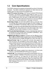
...CIR Infrared, Parallel, PS/2 Mouse, PS/2 Keyboard, RJ45 (Optional), Microphone, Line-In / Line-Out jacks, Standard ATX, AUX and 12V power. 2 Chapter 1: Product introduction Latest P4 Processor Technology: Intel® Pentium® 4 Socket 478 Northwood Processor. and dual channel RDRAM. Intel&#... RIMM4200/ 3200-compliant Rambus DRAMs (RDRAMs) up to the highest standards. 1.2 Core Specifications The P4T533 motherboard is designed and assembled according to 100MB/sec; This ASUS motherboard represents the latest advances and supplies users the finest components available today...
...CIR Infrared, Parallel, PS/2 Mouse, PS/2 Keyboard, RJ45 (Optional), Microphone, Line-In / Line-Out jacks, Standard ATX, AUX and 12V power. 2 Chapter 1: Product introduction Latest P4 Processor Technology: Intel® Pentium® 4 Socket 478 Northwood Processor. and dual channel RDRAM. Intel&#... RIMM4200/ 3200-compliant Rambus DRAMs (RDRAMs) up to the highest standards. 1.2 Core Specifications The P4T533 motherboard is designed and assembled according to 100MB/sec; This ASUS motherboard represents the latest advances and supplies users the finest components available today...
P4T533 User Manual
Page 15
... added external speaker, messages inform you customize voice messages, and offers multi-language support. ASUS P4T533 motherboard user guide 3 No need to buy a new ATX 12V power supply: ASUS EZ Plug™ is a 4pin +12V connector that provides additional power required by P4 CPUs. Bundled Winbond™ Voice Editor software helpsa you of system boot...
... added external speaker, messages inform you customize voice messages, and offers multi-language support. ASUS P4T533 motherboard user guide 3 No need to buy a new ATX 12V power supply: ASUS EZ Plug™ is a 4pin +12V connector that provides additional power required by P4 CPUs. Bundled Winbond™ Voice Editor software helpsa you of system boot...

P4T533 User Manual
Page 16
... Serial Ports (COM1/2 40 USB 1.1 Connectors (Port 1/2 41 PS/2 Keyboard Connector purple) 42 System Voltage Monitor (integrated in ASUS ASIC 11 Onboard LED 24 Onboard AGP Warning LED 7 Modem Connector 29 RJ45 Connector (optional 35 (Audio Models Only) S/PDIF ...Connector lime) 37 Microphone Connector pink) 38 AUX12V1 EZ PLUG Power Supply Connector 5 ATX Power Supply Connector 6 ATX12V Power Supply Connector 1 ATX 4 Chapter 1: Product introduction 1.4 Motherboard Components Before installing the P4T533 motherboard, take time to familiarize yourself with its configuration: ...
... Serial Ports (COM1/2 40 USB 1.1 Connectors (Port 1/2 41 PS/2 Keyboard Connector purple) 42 System Voltage Monitor (integrated in ASUS ASIC 11 Onboard LED 24 Onboard AGP Warning LED 7 Modem Connector 29 RJ45 Connector (optional 35 (Audio Models Only) S/PDIF ...Connector lime) 37 Microphone Connector pink) 38 AUX12V1 EZ PLUG Power Supply Connector 5 ATX Power Supply Connector 6 ATX12V Power Supply Connector 1 ATX 4 Chapter 1: Product introduction 1.4 Motherboard Components Before installing the P4T533 motherboard, take time to familiarize yourself with its configuration: ...
P4T533 User Manual
Page 18
... Adjustable Vcore Voltage (See page 27 and 66.) Temperature, Fan and Voltage Monitoring: ASUS ASIC and the CPU's internal thermal diode monitors temperature to prevent overheating. Pressing the power switch for more than 4 seconds puts the system to sleep mode or to critical ...intrusion detection The motherboard supports chassis intrusion monitoring through the ASUS ASIC. USB2.0: The latest connection standard for RPM and failure. Voltage is available to boost OS Direct Power Management. This feature reduces both power consumption and system noise. A chassis intrusion event is in...
... Adjustable Vcore Voltage (See page 27 and 66.) Temperature, Fan and Voltage Monitoring: ASUS ASIC and the CPU's internal thermal diode monitors temperature to prevent overheating. Pressing the power switch for more than 4 seconds puts the system to sleep mode or to critical ...intrusion detection The motherboard supports chassis intrusion monitoring through the ASUS ASIC. USB2.0: The latest connection standard for RPM and failure. Voltage is available to boost OS Direct Power Management. This feature reduces both power consumption and system noise. A chassis intrusion event is in...
P4T533 User Manual
Page 21
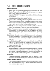
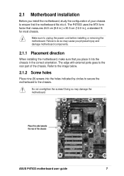
The P4T533 uses the ATX form factor that measures 24.5 cm (9.6 in.) x 30.5 cm (12.0 in the correct orientation. Refer to the chassis. Make sure to the rear part of the chassis. The edge with external ports goes to unplug the power cord before installing or removing the motherboard...motherboard components. 2.1.1 Placement direction When installing the motherboard, make sure that you install the motherboard, study the configuration of the chassis ASUS P4T533 motherboard user guide 7 Failure to do so may damage the motherboard. 2.1 Motherboard installation Before you place it .
The P4T533 uses the ATX form factor that measures 24.5 cm (9.6 in.) x 30.5 cm (12.0 in the correct orientation. Refer to the chassis. Make sure to the rear part of the chassis. The edge with external ports goes to unplug the power cord before installing or removing the motherboard...motherboard components. 2.1.1 Placement direction When installing the motherboard, make sure that you install the motherboard, study the configuration of the chassis ASUS P4T533 motherboard user guide 7 Failure to do so may damage the motherboard. 2.1 Motherboard installation Before you place it .
P4T533 User Manual
Page 22
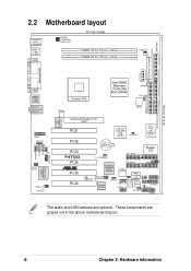
...KBPWR USBPWR01 OVER_VOLT 24.5cm (9.6in) RIMMA (32 bit, 232-pin module) RIMMB (32 bit, 232-pin module) PWRFAN EZ_PLUG ATX Power Connector FLOPPY WARNING PARALLEL PORT C-Media CMI8738 6CH Audio Controller MODEM AUX CD AAPANEL COM2 USB2.0 T: USB1 B: USB2 Top:Line In Center:... CPU_FAN ATX12V DSWF Accelerated Graphics Port AGP PCI1 Intel I/O Controller Hub (ICH2) CLCMOS ASUS ASIC with Hardware Monitor PCI2 PCI3 P4T533 PCI4 ® PCI5 PCI6 CR2032 3V Lithium Cell CMOS Power SEC_RAID Super I/O CH_FAN PRI_RAID JEN SMB PROMISE PDC20276 ATA133 Controller DSWMUL RAID_SW WOR MODESEL...
...KBPWR USBPWR01 OVER_VOLT 24.5cm (9.6in) RIMMA (32 bit, 232-pin module) RIMMB (32 bit, 232-pin module) PWRFAN EZ_PLUG ATX Power Connector FLOPPY WARNING PARALLEL PORT C-Media CMI8738 6CH Audio Controller MODEM AUX CD AAPANEL COM2 USB2.0 T: USB1 B: USB2 Top:Line In Center:... CPU_FAN ATX12V DSWF Accelerated Graphics Port AGP PCI1 Intel I/O Controller Hub (ICH2) CLCMOS ASUS ASIC with Hardware Monitor PCI2 PCI3 P4T533 PCI4 ® PCI5 PCI6 CR2032 3V Lithium Cell CMOS Power SEC_RAID Super I/O CH_FAN PRI_RAID JEN SMB PROMISE PDC20276 ATA133 Controller DSWMUL RAID_SW WOR MODESEL...

P4T533 User Manual
Page 23
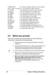
...11) FLOPPY p. 37 Floppy Disk Drive Connector (34-1 pin) 12) PWR, CPU, CHA_FAN p. 37 Power, CPU and Chassis Fan Connectors (Three 3 pin) 13) ATXPWR, p. 38 ATX Power Connectors (20-pin, 4-pin, 4-pin ) 12V EZ_PLUG, ATX12V 14) SMB p. 38 SMBus Connector ...(6-1 pin) 15) USB11_34 p. 39 USB Headers (10-1 pin) 16) USB20_34 p. 39 USB 2.0 Headers (10-1 pin) 17) CD, AUX, MODEM p. 40 Internal Audio Connectors (Three 4-1 pin) (optional) 18) CHASSIS p. 40 Chassis Open Alarm Lead (4-1 pin) ASUS P4T533...
...11) FLOPPY p. 37 Floppy Disk Drive Connector (34-1 pin) 12) PWR, CPU, CHA_FAN p. 37 Power, CPU and Chassis Fan Connectors (Three 3 pin) 13) ATXPWR, p. 38 ATX Power Connectors (20-pin, 4-pin, 4-pin ) 12V EZ_PLUG, ATX12V 14) SMB p. 38 SMBus Connector ...(6-1 pin) 15) USB11_34 p. 39 USB Headers (10-1 pin) 16) USB20_34 p. 39 USB 2.0 Headers (10-1 pin) 17) CD, AUX, MODEM p. 40 Internal Audio Connectors (Three 4-1 pin) (optional) 18) CHASSIS p. 40 Chassis Open Alarm Lead (4-1 pin) ASUS P4T533...
P4T533 User Manual
Page 24
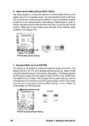
... grounded object or to a metal object, such as the power supply case, before handling components to avoid damaging them . 4. 19) SMARTCON p. 41 Smart Card Reader connector (14-1 pin) (optional) 20) FP_LO_SWL, FP_LO_SWR p. 41 Line-out Selector Jumpers (Two 2 pin) 21) AFPANEL p. 42 ASUS iPanel / Infrared Connector (24-1 pin) 22) LINE_IN p. 43 Front...
... grounded object or to a metal object, such as the power supply case, before handling components to avoid damaging them . 4. 19) SMARTCON p. 41 Smart Card Reader connector (14-1 pin) (optional) 20) FP_LO_SWL, FP_LO_SWR p. 41 Line-out Selector Jumpers (Two 2 pin) 21) AFPANEL p. 42 ASUS iPanel / Infrared Connector (24-1 pin) 22) LINE_IN p. 43 Front...
P4T533 User Manual
Page 33
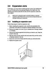
Before installing the expansion card, read the documentation that came with the screw you intend to unplug the power cord before adding or removing expansion cards. 2.6 Expansion slots In the future, you may cause you physical injury and damage motherboard components. ... 6. Replace the system cover. Align the card connector with the slot and press firmly until the card is already installed in a chassis). 3. ASUS P4T533 motherboard user guide 19 The motherboard has six PCI slots and one Accelerated Graphics Port (AGP) slot. Remove the system unit cover (if your motherboard...
Before installing the expansion card, read the documentation that came with the screw you intend to unplug the power cord before adding or removing expansion cards. 2.6 Expansion slots In the future, you may cause you physical injury and damage motherboard components. ... 6. Replace the system cover. Align the card connector with the slot and press firmly until the card is already installed in a chassis). 3. ASUS P4T533 motherboard user guide 19 The motherboard has six PCI slots and one Accelerated Graphics Port (AGP) slot. Remove the system unit cover (if your motherboard...

P4T533 User Manual
Page 35
The slots support PCI cards such as a LAN card, SCSI card, USB card, and other cards that supports AGP 4X 1.5V cards. ASUS P4T533 motherboard user guide 21 The following figure shows a LAN card installed on a PCI slot. 2.6.4 AGP slot This motherboard has an Accelerated ... warning light lights up and the board will not power up; To avoid damaging your AGP graphics card, your computer's power supply should be unplugged before inserting your graphics card into the slot. CAUTION! P4T533 ® Keyed for 1.5v P4T533 Accelerated Graphics Port (AGP) To avoid damaging your AGP...
The slots support PCI cards such as a LAN card, SCSI card, USB card, and other cards that supports AGP 4X 1.5V cards. ASUS P4T533 motherboard user guide 21 The following figure shows a LAN card installed on a PCI slot. 2.6.4 AGP slot This motherboard has an Accelerated ... warning light lights up and the board will not power up; To avoid damaging your AGP graphics card, your computer's power supply should be unplugged before inserting your graphics card into the slot. CAUTION! P4T533 ® Keyed for 1.5v P4T533 Accelerated Graphics Port (AGP) To avoid damaging your AGP...
P4T533 User Manual
Page 39
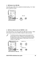
...) 23 Disable 5. 4. USBPWR_12 12 23 +5V (Default) +5VSB USBPWR_34 P4T533 ® 12 23 P4T533 USB Device Wake Up +5V (Default) +5VSB ASUS P4T533 motherboard user guide 25 Reset these jumpers to pins [2-3] (+5VSB) to disable the header. The total current consumed must NOT exceed the power supply capability (+5VSB) whether under normal condition or in...
...) 23 Disable 5. 4. USBPWR_12 12 23 +5V (Default) +5VSB USBPWR_34 P4T533 ® 12 23 P4T533 USB Device Wake Up +5V (Default) +5VSB ASUS P4T533 motherboard user guide 25 Reset these jumpers to pins [2-3] (+5VSB) to disable the header. The total current consumed must NOT exceed the power supply capability (+5VSB) whether under normal condition or in...
P4T533 User Manual
Page 40
... Select +5VSB to disable or enable the keyboard power up (by pressing ) . Make sure a test is made using the Audio Driver software setup available on the +5VSB lead. KBPWR 12 23 P4T533 ® +5V (Default) P4T533 Keyboard Power Setting +5VSB 26 Chapter 2: Hardware information therfore,... it may be set to Enable. (The computer will not power ON if you to enable keyboard power up function. The default is set in 4.5.1 Power Up Control:Wake On...
... Select +5VSB to disable or enable the keyboard power up (by pressing ) . Make sure a test is made using the Audio Driver software setup available on the +5VSB lead. KBPWR 12 23 P4T533 ® +5V (Default) P4T533 Keyboard Power Setting +5VSB 26 Chapter 2: Hardware information therfore,... it may be set to Enable. (The computer will not power ON if you to enable keyboard power up function. The default is set in 4.5.1 Power Up Control:Wake On...

P4T533 User Manual
Page 43
The RAM data in CMOS. Turn OFF the computer and unplug the power cord. 2. Re-install the battery. 6. Plug the power cord and turn ON the computer. 7. 11. To erase the RTC RAM: 1. Short the jumper by the onboard button cell battery. You can clear the ... CLRTC Short jumper to re-enter data. Remove the battery. 3. Hold down the key during the boot process and enter BIOS setup to clear CMOS ASUS P4T533 motherboard user guide 29 Clear RTC RAM (2 pin CLRTC) This jumper allows you to clear the Real Time Clock (RTC) RAM in CMOS, that include...
The RAM data in CMOS. Turn OFF the computer and unplug the power cord. 2. Re-install the battery. 6. Plug the power cord and turn ON the computer. 7. 11. To erase the RTC RAM: 1. Short the jumper by the onboard button cell battery. You can clear the ... CLRTC Short jumper to re-enter data. Remove the battery. 3. Hold down the key during the boot process and enter BIOS setup to clear CMOS ASUS P4T533 motherboard user guide 29 Clear RTC RAM (2 pin CLRTC) This jumper allows you to clear the Real Time Clock (RTC) RAM in CMOS, that include...


