P4T533 User Manual
Page 4
... this guide iii How this guide is organized iii Conventions used in this guide iii Safety information vi FCC/CDC statements vii ASUS contact information viii P4T533 specifications summary ix Chapter 1: Product introduction 1 Welcome 1 1.1 Package contents 1 1.2 Core Specifications 2 1.3 Special Features 3 ... 12 2.4.3 Installing the heatsink and fan 13 2.4.4 Connecting the CPU fan cable 15 2.5 System memory 16 2.5.1 Overview 16 2.5.2 Installing Memory 17 2.5.3 Removing Memory 18 2.5.4 General RIMM Memos 18 2.6 Expansion slots 19 2.6.1 Installing an expansion card 19 2.6.2 ...
... this guide iii How this guide is organized iii Conventions used in this guide iii Safety information vi FCC/CDC statements vii ASUS contact information viii P4T533 specifications summary ix Chapter 1: Product introduction 1 Welcome 1 1.1 Package contents 1 1.2 Core Specifications 2 1.3 Special Features 3 ... 12 2.4.3 Installing the heatsink and fan 13 2.4.4 Connecting the CPU fan cable 15 2.5 System memory 16 2.5.1 Overview 16 2.5.2 Installing Memory 17 2.5.3 Removing Memory 18 2.5.4 General RIMM Memos 18 2.6 Expansion slots 19 2.6.1 Installing an expansion card 19 2.6.2 ...

P4T533 User Manual
Page 9
memory. P4T533 specifications summary CPU Socket 478 for 2 additional USB ports CPU/Power/Chassis fan connectors 20-pin/4-pin ATX power connectors IDE LED/Power LED connectors ... 8738-MX 6-Channel PCI Audio Controller Promise® ATA133 / RAID 0/1 IDE controller Intel® 8256ET ethernet controller (optional) ASUS JumperFree™ mode ASUS POST Reporter™ ASUS EZ Plug™ ASUS EZ Flash ASUS MyLogo2™ ASUS Q-Fan ASUS Multi-language BIOS S/PDIF In/Out Module bundled (optional) Power Loss Restart Adjustable CPU VCORE AGP warning LED...
memory. P4T533 specifications summary CPU Socket 478 for 2 additional USB ports CPU/Power/Chassis fan connectors 20-pin/4-pin ATX power connectors IDE LED/Power LED connectors ... 8738-MX 6-Channel PCI Audio Controller Promise® ATA133 / RAID 0/1 IDE controller Intel® 8256ET ethernet controller (optional) ASUS JumperFree™ mode ASUS POST Reporter™ ASUS EZ Plug™ ASUS EZ Flash ASUS MyLogo2™ ASUS Q-Fan ASUS Multi-language BIOS S/PDIF In/Out Module bundled (optional) Power Loss Restart Adjustable CPU VCORE AGP warning LED...
P4T533 User Manual
Page 12
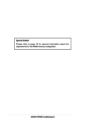
Please refer to page 18 for special information about the requirements for the RIMM memory configuration. ASUS P4T533 motherboard Special Notice!
Please refer to page 18 for special information about the requirements for the RIMM memory configuration. ASUS P4T533 motherboard Special Notice!
P4T533 User Manual
Page 13
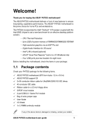
...memory of RIMM4200/RIMM3200 RDRAM ~ High-resolution graphics via an AGP Pro slot ~ Digital Audio Interface for 3D sound ~ Intel® LAN onboard (optional) ~ ASUS® Vocal Post Reporter™ built-in to I /O Shield 1x C-RIMM continuity module If any of new features to ensure long-lasting, superlative performance. ASUS P4T533... motherboard user guide 1 Welcome! Thank you for buying the ASUS® P4T533 motherboard! The ASUS P4T533 motherboard delivers a host of the above items is the prime choice ...
...memory of RIMM4200/RIMM3200 RDRAM ~ High-resolution graphics via an AGP Pro slot ~ Digital Audio Interface for 3D sound ~ Intel® LAN onboard (optional) ~ ASUS® Vocal Post Reporter™ built-in to I /O Shield 1x C-RIMM continuity module If any of new features to ensure long-lasting, superlative performance. ASUS P4T533... motherboard user guide 1 Welcome! Thank you for buying the ASUS® P4T533 motherboard! The ASUS P4T533 motherboard delivers a host of the above items is the prime choice ...
P4T533 User Manual
Page 14
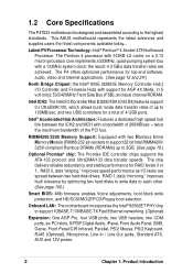
...LAN: The motherboard incorporates the Intel® 82562ET PHY chip to the highest standards. RIMM4200/3200 Memory Support: Equipped with support for a total of the PCI bus. The chip delivers reliable redundancy .../100, which allows burst mode data transfer rates of 266MB/sec - 1.2 Core Specifications The P4T533 motherboard is designed and assembled according to support 10BASE-T/100BASE-TX Fast Ethernet networking. (Optional) ...B4) features support for RAID levels 0 or 1. This ASUS motherboard represents the latest advances and supplies users the finest components available today...
...LAN: The motherboard incorporates the Intel® 82562ET PHY chip to the highest standards. RIMM4200/3200 Memory Support: Equipped with support for a total of the PCI bus. The chip delivers reliable redundancy .../100, which allows burst mode data transfer rates of 266MB/sec - 1.2 Core Specifications The P4T533 motherboard is designed and assembled according to support 10BASE-T/100BASE-TX Fast Ethernet networking. (Optional) ...B4) features support for RAID levels 0 or 1. This ASUS motherboard represents the latest advances and supplies users the finest components available today...

P4T533 User Manual
Page 16
... prevents accidental damage. 1.4 Motherboard Components Before installing the P4T533 motherboard, take time to familiarize yourself with its configuration: understanding the motherboard makes upgrading easy. Processor Support Chipsets Main Memory Expansion Slots Major System I/O Hardware Monitoring Special Feature Network... Serial Ports (COM1/2 40 USB 1.1 Connectors (Port 1/2 41 PS/2 Keyboard Connector purple) 42 System Voltage Monitor (integrated in ASUS ASIC 11 Onboard LED 24 Onboard AGP Warning LED 7 Modem Connector 29 RJ45 Connector (optional 35 (Audio Models Only) S/PDIF ...
... prevents accidental damage. 1.4 Motherboard Components Before installing the P4T533 motherboard, take time to familiarize yourself with its configuration: understanding the motherboard makes upgrading easy. Processor Support Chipsets Main Memory Expansion Slots Major System I/O Hardware Monitoring Special Feature Network... Serial Ports (COM1/2 40 USB 1.1 Connectors (Port 1/2 41 PS/2 Keyboard Connector purple) 42 System Voltage Monitor (integrated in ASUS ASIC 11 Onboard LED 24 Onboard AGP Warning LED 7 Modem Connector 29 RJ45 Connector (optional 35 (Audio Models Only) S/PDIF ...
P4T533 User Manual
Page 18
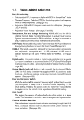
... (See page 23, 24 and 66.) • Adjustable Vcore Voltage (See page 27 and 66.) Temperature, Fan and Voltage Monitoring: ASUS ASIC and the CPU's internal thermal diode monitors temperature to accommodate the S/PDIF (Sony/Philips Digital Interface Output module -- Pressing the power ...switch While the system is in sleep mode. Chassis intrusion detection The motherboard supports chassis intrusion monitoring through the ASUS ASIC. A chassis intrusion event is retained in the system memory for fine-tuning system bus frequency from at 480Mb/s. (See page 39.) Digital Audio: On audio models...
... (See page 23, 24 and 66.) • Adjustable Vcore Voltage (See page 27 and 66.) Temperature, Fan and Voltage Monitoring: ASUS ASIC and the CPU's internal thermal diode monitors temperature to accommodate the S/PDIF (Sony/Philips Digital Interface Output module -- Pressing the power ...switch While the system is in sleep mode. Chassis intrusion detection The motherboard supports chassis intrusion monitoring through the ASUS ASIC. A chassis intrusion event is retained in the system memory for fine-tuning system bus frequency from at 480Mb/s. (See page 39.) Digital Audio: On audio models...
P4T533 User Manual
Page 22
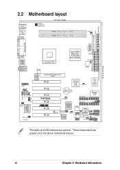
... LINE_IN LO_L LO_R BCS2 BCS1 SPDIF_C LED1 Intel LAN Controller Socket 478 Intel 850E Memory Controller Hub (MCH) TRPWR CPU_FAN ATX12V DSWF Accelerated Graphics Port AGP PCI1 Intel I/O Controller Hub (ICH2) CLCMOS ASUS ASIC with Hardware Monitor PCI2 PCI3 P4T533 PCI4 ® PCI5 PCI6 CR2032 3V Lithium Cell CMOS Power SEC_RAID Super I/O CH_FAN...
... LINE_IN LO_L LO_R BCS2 BCS1 SPDIF_C LED1 Intel LAN Controller Socket 478 Intel 850E Memory Controller Hub (MCH) TRPWR CPU_FAN ATX12V DSWF Accelerated Graphics Port AGP PCI1 Intel I/O Controller Hub (ICH2) CLCMOS ASUS ASIC with Hardware Monitor PCI2 PCI3 P4T533 PCI4 ® PCI5 PCI6 CR2032 3V Lithium Cell CMOS Power SEC_RAID Super I/O CH_FAN...

P4T533 User Manual
Page 23
... Expansion Slots 1) Socket 478 p. 12 Installing the CPU 2) Heatsink p. 13 Installing the Heatsink and Fan 3) Memory p. 16 System Memory Support 4) PCI 1/2/3/4/5/6 p. 19 32-bit PCI Bus Expansion Slots 5) AGP Pro p. 21 Accelerated Graphics Slot Motherboard Settings (Switches and Jumpers) 1) JEN p. 22 JumperFree Mode Setting (...) USB20_34 p. 39 USB 2.0 Headers (10-1 pin) 17) CD, AUX, MODEM p. 40 Internal Audio Connectors (Three 4-1 pin) (optional) 18) CHASSIS p. 40 Chassis Open Alarm Lead (4-1 pin) ASUS P4T533 motherboard user guide 9
... Expansion Slots 1) Socket 478 p. 12 Installing the CPU 2) Heatsink p. 13 Installing the Heatsink and Fan 3) Memory p. 16 System Memory Support 4) PCI 1/2/3/4/5/6 p. 19 32-bit PCI Bus Expansion Slots 5) AGP Pro p. 21 Accelerated Graphics Slot Motherboard Settings (Switches and Jumpers) 1) JEN p. 22 JumperFree Mode Setting (...) USB20_34 p. 39 USB 2.0 Headers (10-1 pin) 17) CD, AUX, MODEM p. 40 Internal Audio Connectors (Three 4-1 pin) (optional) 18) CHASSIS p. 40 Chassis Open Alarm Lead (4-1 pin) ASUS P4T533 motherboard user guide 9

P4T533 User Manual
Page 30
...sockets. These sockets support 32-bit RIMMs in a Rambus interface. A C-RIMM is necessary to complete the socket that is unpopulated.) TOTAL SYSTEM MEMORY = (2GB Max) C-RIMMs (Continuity RIMM) must be used to avoid breaking the signal lines, which are a serial connection in the following ...sizes: 128, 256 and 512Mbit RDRAM RIMMs. Location Memory Module Subtotal RIMM1 (Rows 0&1) RDRAM x 1 and/or C-RIMM (Use when socket is unpopulated.) RIMM2 (Rows 2&3) RDRAM x 1 and/or C-RIMM...
...sockets. These sockets support 32-bit RIMMs in a Rambus interface. A C-RIMM is necessary to complete the socket that is unpopulated.) TOTAL SYSTEM MEMORY = (2GB Max) C-RIMMs (Continuity RIMM) must be used to avoid breaking the signal lines, which are a serial connection in the following ...sizes: 128, 256 and 512Mbit RDRAM RIMMs. Location Memory Module Subtotal RIMM1 (Rows 0&1) RDRAM x 1 and/or C-RIMM (Use when socket is unpopulated.) RIMM2 (Rows 2&3) RDRAM x 1 and/or C-RIMM...
P4T533 User Manual
Page 31
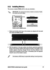
... in place. No hardware or BIOS setup is required after adding or removing memory. ASUS P4T533 motherboard user guide 17 If necessary, push the ejectors inward to secure the module in the module are aligned with Heat Spreader P4T533 ® C-RIMM P4T533 184-Pin RIMM Sockets 1. RIMM Sockets RIMM with the small ribs inside the...
... in place. No hardware or BIOS setup is required after adding or removing memory. ASUS P4T533 motherboard user guide 17 If necessary, push the ejectors inward to secure the module in the module are aligned with Heat Spreader P4T533 ® C-RIMM P4T533 184-Pin RIMM Sockets 1. RIMM Sockets RIMM with the small ribs inside the...
P4T533 User Manual
Page 32
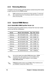
RIMM modules become extremely hot during operation. Visit the ASUS website for more updates: http://www.asus.com RIMM4200 modules require use RIMM4200 modules with this motherboard. 2.5.3 Removing Memory: To release a memory module, push both ejectors outward and pull the module straight up and out...cool off before removing them. 2.5.4 General RIMM Memos: 32-bit 1066/800MHz RIMM Qualified Vendor List The following table lists qualified memory modules that have been tested and for this motherboard: Vendor Samsung Samsung Samsung Samsung Samsung Samsung Elpida Elpida Model / Device Number ...
RIMM modules become extremely hot during operation. Visit the ASUS website for more updates: http://www.asus.com RIMM4200 modules require use RIMM4200 modules with this motherboard. 2.5.3 Removing Memory: To release a memory module, push both ejectors outward and pull the module straight up and out...cool off before removing them. 2.5.4 General RIMM Memos: 32-bit 1066/800MHz RIMM Qualified Vendor List The following table lists qualified memory modules that have been tested and for this motherboard: Vendor Samsung Samsung Samsung Samsung Samsung Samsung Elpida Elpida Model / Device Number ...

P4T533 User Manual
Page 43
... RTC RAM CLRTC Short jumper to re-enter data. Hold down the key during the boot process and enter BIOS setup to clear CMOS ASUS P4T533 motherboard user guide 29 Clear RTC RAM (2 pin CLRTC) This jumper allows you to clear the Real Time Clock (RTC) RAM in CMOS, that include ... the power cord and turn ON the computer. 7. The RAM data in CMOS. Remove the battery. 3. Remove the jumper cap. 5. You can clear the CMOS memory of date, time, and system setup parameters by the onboard button cell battery. Turn OFF the computer and unplug the power cord. 2. Short the jumper...
... RTC RAM CLRTC Short jumper to re-enter data. Hold down the key during the boot process and enter BIOS setup to clear CMOS ASUS P4T533 motherboard user guide 29 Clear RTC RAM (2 pin CLRTC) This jumper allows you to clear the Real Time Clock (RTC) RAM in CMOS, that include ... the power cord and turn ON the computer. 7. The RAM data in CMOS. Remove the battery. 3. Remove the jumper cap. 5. You can clear the CMOS memory of date, time, and system setup parameters by the onboard button cell battery. Turn OFF the computer and unplug the power cord. 2. Short the jumper...
P4T533 User Manual
Page 63
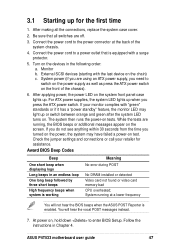
... order: a. System running , the BIOS beeps or additional messages appear on the screen. You will not hear the BIOS beeps when the ASUS POST Reporter is enabled. System power (if you are using an ATX power supply, you need to the power connector at a lower frequency... DRAM installed or detected Video card not found or video card memory bad CPU overheated; After applying power, the power LED on tests. If your retailer for the first time 1. While the tests are off. 3. Monitor b. ASUS P4T533 motherboard user guide 47 Follow the instructions in Chapter 4. External SCSI...
... order: a. System running , the BIOS beeps or additional messages appear on the screen. You will not hear the BIOS beeps when the ASUS POST Reporter is enabled. System power (if you are using an ATX power supply, you need to the power connector at a lower frequency... DRAM installed or detected Video card not found or video card memory bad CPU overheated; After applying power, the power LED on tests. If your retailer for the first time 1. While the tests are off. 3. Monitor b. ASUS P4T533 motherboard user guide 47 Follow the instructions in Chapter 4. External SCSI...
P4T533 User Manual
Page 64
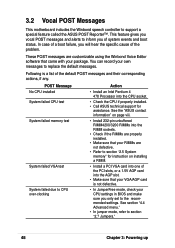
...you will hear the specific cause of the problem. POST Message No CPU installed System failed CPU test System failed memory test System failed VGA test System failed due to section "2.5 System memory" for instruction on installing a RIMM. • Install a PCI VGA card into one of the PCI slots,... or a 1.5V AGP card into the CPU socket. • Check the CPU if properly installed. • Call ASUS technical support for assistance. 3.2 Vocal POST...
...you will hear the specific cause of the problem. POST Message No CPU installed System failed CPU test System failed memory test System failed VGA test System failed due to section "2.5 System memory" for instruction on installing a RIMM. • Install a PCI VGA card into one of the PCI slots,... or a 1.5V AGP card into the CPU socket. • Check the CPU if properly installed. • Call ASUS technical support for assistance. 3.2 Vocal POST...
P4T533 User Manual
Page 70
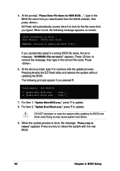
... 1, "Update Main BIOS area," press Y to remove the message, then type in File] BIOS Version: P4T533 Boot Block WARNING! When the update process is done, the message, "Press a key to look for NEW... 5. Continue to update. Pressing N exits the EZ Flash utility and reboots the system without updating the BIOS. Flash Memory: SST 49LF004 1. appears. Update Boot Block area (Y/N)? _ (Y/N)? _ 7. DO NOT shutdown or reset the system while... the BIOS file name that you downloaded from the ASUS website, then press . Press any key to continue with the new BIOS. 52 Chapter 4: BIOS ...
... 1, "Update Main BIOS area," press Y to remove the message, then type in File] BIOS Version: P4T533 Boot Block WARNING! When the update process is done, the message, "Press a key to look for NEW... 5. Continue to update. Pressing N exits the EZ Flash utility and reboots the system without updating the BIOS. Flash Memory: SST 49LF004 1. appears. Update Boot Block area (Y/N)? _ (Y/N)? _ 7. DO NOT shutdown or reset the system while... the BIOS file name that you downloaded from the ASUS website, then press . Press any key to continue with the new BIOS. 52 Chapter 4: BIOS ...
P4T533 User Manual
Page 71
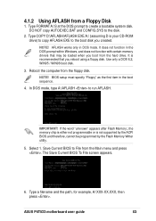
...press . Type a filename and the path, for example, A:\XXX-XX.XXX, then press . It is not supported by the Flash Memory Writer utility. 5. Select 1. ASUS P4T533 motherboard user guide 53 Reboot the computer from a Floppy Disk 1. The Save Current BIOS To File screen appears. 6. AFLASH works only ...to File from the hard drive. Save Current BIOS to create a bootable system disk. If the word "unknown" appears after Flash Memory:, the memory chip is either not programmable or is recommended that may be programmed by the ACPI BIOS and therefore, cannot be loaded when you...
...press . Type a filename and the path, for example, A:\XXX-XX.XXX, then press . It is not supported by the Flash Memory Writer utility. 5. Select 1. ASUS P4T533 motherboard user guide 53 Reboot the computer from a Floppy Disk 1. The Save Current BIOS To File screen appears. 6. AFLASH works only ...to File from the hard drive. Save Current BIOS to create a bootable system disk. If the word "unknown" appears after Flash Memory:, the memory chip is either not programmable or is recommended that may be programmed by the ACPI BIOS and therefore, cannot be loaded when you...

P4T533 User Manual
Page 73
...Follow the onscreen instructions to program the new BIOS information into the Flash ROM. If the Flash Memory Writer utility is updated automatically only when necessary. If you encounter problems while updating the new ...BIOS, DO NOT turn off the system because this happens, call the ASUS service center for support. 7. The boot block is not able to successfully update a complete BIOS file... to the boot disk. If this may not boot. ASUS P4T533 motherboard user guide 55 When the programming is done, the message "Flashed Successfully" appears. 8.
...Follow the onscreen instructions to program the new BIOS information into the Flash ROM. If the Flash Memory Writer utility is updated automatically only when necessary. If you encounter problems while updating the new ...BIOS, DO NOT turn off the system because this happens, call the ASUS service center for support. 7. The boot block is not able to successfully update a complete BIOS file... to the boot disk. If this may not boot. ASUS P4T533 motherboard user guide 55 When the programming is done, the message "Flashed Successfully" appears. 8.
P4T533 User Manual
Page 83
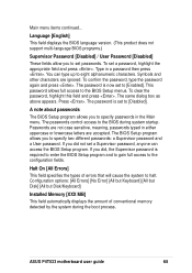
... to gain full access to specify passwords in the Main menu. Halt On [All Errors] This field specifies the types of conventional memory detected by the system during system startup. Configuration options: [All Errors] [No Error] [All but Keyboard] [All but Disk] [...BIOS Setup program. Passwords are not case sensitive, meaning, passwords typed in a password then press . If you to the configuration fields. ASUS P4T533 motherboard user guide 65 Symbols and other characters are accepted. To clear the password, highlight this field and press . A note about passwords ...
... to gain full access to specify passwords in the Main menu. Halt On [All Errors] This field specifies the types of conventional memory detected by the system during system startup. Configuration options: [All Errors] [No Error] [All but Keyboard] [All but Disk] [...BIOS Setup program. Passwords are not case sensitive, meaning, passwords typed in a password then press . If you to the configuration fields. ASUS P4T533 motherboard user guide 65 Symbols and other characters are accepted. To clear the password, highlight this field and press . A note about passwords ...
P4T533 User Manual
Page 84
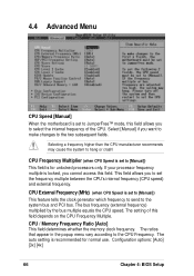
... allows you to the CPU Frequency. The bus frequency (external frequency) multiplied by the bus multiple equals the CPU speed. CPU / Memory Frequency Ratio [Auto] This field determines whether the memory clock frequency. Configuration options: [Auto] [3x] [4x] 66 Chapter 4: BIOS Setup If your processor frequency multiple is recommended for unlocked processors...
... allows you to the CPU Frequency. The bus frequency (external frequency) multiplied by the bus multiple equals the CPU speed. CPU / Memory Frequency Ratio [Auto] This field determines whether the memory clock frequency. Configuration options: [Auto] [3x] [4x] 66 Chapter 4: BIOS Setup If your processor frequency multiple is recommended for unlocked processors...


