
P4T533 User Manual
Page 2
...number of ASUSTeK COMPUTER INC. ("ASUS"). For previous or updated manuals, BIOS, drivers, or product release information, contact ASUS at: http://www.asus.com or through any means, except documentation kept by the purchaser for each product design represented by ASUS; SPECIFICATIONS AND INFORMATION CONTAINED IN THIS...the express written permission of the product is authorized in any form or by any of the manual revision number. Checklist P4T533 E1109 Manual 1.01 August 2002 Copyright © 2002 ASUSTeK COMPUTER INC. Product warranty or service will not be registered trademarks...
...number of ASUSTeK COMPUTER INC. ("ASUS"). For previous or updated manuals, BIOS, drivers, or product release information, contact ASUS at: http://www.asus.com or through any means, except documentation kept by the purchaser for each product design represented by ASUS; SPECIFICATIONS AND INFORMATION CONTAINED IN THIS...the express written permission of the product is authorized in any form or by any of the manual revision number. Checklist P4T533 E1109 Manual 1.01 August 2002 Copyright © 2002 ASUSTeK COMPUTER INC. Product warranty or service will not be registered trademarks...
P4T533 User Manual
Page 3
... perform set-up . Tips and helpful information. How this guide This user manual contains complete information for installing the ASUS P4T533 motherboard. IMPORTANT! iii WARNING! A summary of product features and special attributes of the BIOS parameters are supplied. • Chapter 5: Software support. How to yourself. NOTE! Information to prevent damage to complete a task...
... perform set-up . Tips and helpful information. How this guide This user manual contains complete information for installing the ASUS P4T533 motherboard. IMPORTANT! iii WARNING! A summary of product features and special attributes of the BIOS parameters are supplied. • Chapter 5: Software support. How to yourself. NOTE! Information to prevent damage to complete a task...
P4T533 User Manual
Page 5
... from a Floppy Disk 53 4.1.3 Updating BIOS procedures 54 4.2 BIOS Setup program 56 4.3 Main menu 59 4.4 Advanced Menu 66 4.5 Power Menu 74 4.6 Boot Menu 79 4.7 Exit Menu 81 Chapter 5: Software support 83 5.1 Install an operating system 83 5.2 Support CD information 83 5.3 P4T533 Motherboard Support CD 84 5.4 ASUS PC Probe 86 5.5 ASUS Live Update 91 5.6 3Deep Color...
... from a Floppy Disk 53 4.1.3 Updating BIOS procedures 54 4.2 BIOS Setup program 56 4.3 Main menu 59 4.4 Advanced Menu 66 4.5 Power Menu 74 4.6 Boot Menu 79 4.7 Exit Menu 81 Chapter 5: Software support 83 5.1 Install an operating system 83 5.2 Support CD information 83 5.3 P4T533 Motherboard Support CD 84 5.4 ASUS PC Probe 86 5.5 ASUS Live Update 91 5.6 3Deep Color...

P4T533 User Manual
Page 9
...Promise® ATA133 / RAID 0/1 IDE controller Intel® 8256ET ethernet controller (optional) ASUS JumperFree™ mode ASUS POST Reporter™ ASUS EZ Plug™ ASUS EZ Flash ASUS MyLogo2™ ASUS Q-Fan ASUS Multi-language BIOS S/PDIF In/Out Module bundled (optional) Power Loss Restart Adjustable CPU VCORE AGP warning ...Bus (FSB) 533 / 400 MHz Memory 2 x 232-pin 32-bit RIMM4200/3200-compliant Rambus DRAMs (RDRAMs) up to 2GB. P4T533 specifications summary CPU Socket 478 for 2 additional USB ports CPU/Power/Chassis fan connectors 20-pin/4-pin ATX power connectors IDE LED/Power ...
...Promise® ATA133 / RAID 0/1 IDE controller Intel® 8256ET ethernet controller (optional) ASUS JumperFree™ mode ASUS POST Reporter™ ASUS EZ Plug™ ASUS EZ Flash ASUS MyLogo2™ ASUS Q-Fan ASUS Multi-language BIOS S/PDIF In/Out Module bundled (optional) Power Loss Restart Adjustable CPU VCORE AGP warning ...Bus (FSB) 533 / 400 MHz Memory 2 x 232-pin 32-bit RIMM4200/3200-compliant Rambus DRAMs (RDRAMs) up to 2GB. P4T533 specifications summary CPU Socket 478 for 2 additional USB ports CPU/Power/Chassis fan connectors 20-pin/4-pin ATX power connectors IDE LED/Power ...

P4T533 User Manual
Page 10
DMI 2.0, WOL/WOR by PME, chassis intrusion, SMBus ATX form factor: 12 in x 9.6 in (30.5 cm x 24.5 cm) Device drivers ASUS PC Probe™ ASUS LiveUpdate™ Winbond™ Voice Editor Trend Micro™ PC-cillin 2002 anti-virus software CyberLink™ Power Player SE, VideoLive Mail x P4T533 specifications summary IBnIdOuSstfreyatsutraensdard MInadnuasgtreyasbtialintydard FMoarnmagFeaacbtoilrity SFourpmpoFrat cCtDorcontents Support CD contents 4Mb Flash ROM, Award BIOS, TCAV, PnP, DMI2.0, WIM2.0, SM BIOS 2.3, ASUS EZ Flash PCI 2.2, USB 2.0, USB 1.1 WfM 2.0.
DMI 2.0, WOL/WOR by PME, chassis intrusion, SMBus ATX form factor: 12 in x 9.6 in (30.5 cm x 24.5 cm) Device drivers ASUS PC Probe™ ASUS LiveUpdate™ Winbond™ Voice Editor Trend Micro™ PC-cillin 2002 anti-virus software CyberLink™ Power Player SE, VideoLive Mail x P4T533 specifications summary IBnIdOuSstfreyatsutraensdard MInadnuasgtreyasbtialintydard FMoarnmagFeaacbtoilrity SFourpmpoFrat cCtDorcontents Support CD contents 4Mb Flash ROM, Award BIOS, TCAV, PnP, DMI2.0, WIM2.0, SM BIOS 2.3, ASUS EZ Flash PCI 2.2, USB 2.0, USB 1.1 WfM 2.0.
P4T533 User Manual
Page 14
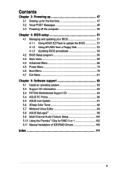
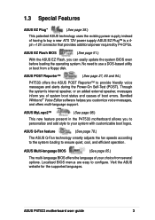
...100, which allows burst mode data transfer rates of 266MB/sec - 1.2 Core Specifications The P4T533 motherboard is designed and assembled according to 2GB. (See page 18.) Optional Promise® ... IDE controller chips supports the ATA-133 protocol and UltraDMA/133 data transfer speeds. This ASUS motherboard represents the latest advances and supplies users the finest components available today... Onboard LAN:...RIMM4200/ 3200-compliant Rambus DRAMs (RDRAMs) up to each other. (See page 100.) Smart BIOS: 4Mb firmware enables Vcore adjustments, boot block write protection, and HD/SCSI/MO/ZIP/CD/...
...100, which allows burst mode data transfer rates of 266MB/sec - 1.2 Core Specifications The P4T533 motherboard is designed and assembled according to 2GB. (See page 18.) Optional Promise® ... IDE controller chips supports the ATA-133 protocol and UltraDMA/133 data transfer speeds. This ASUS motherboard represents the latest advances and supplies users the finest components available today... Onboard LAN:...RIMM4200/ 3200-compliant Rambus DRAMs (RDRAMs) up to each other. (See page 100.) Smart BIOS: 4Mb firmware enables Vcore adjustments, boot block write protection, and HD/SCSI/MO/ZIP/CD/...
P4T533 User Manual
Page 15
... your choice from a floppy disk. ASUS Multi-language BIOS (See page 65.) The multi-language BIOS offers the language of your system with customizable boot logos. Localized BIOS menus are easy to use a DOS-based utility or boot from several options. Visit the ASUS website for the supported languages. ASUS P4T533 motherboard user guide 3 No need to...
... your choice from a floppy disk. ASUS Multi-language BIOS (See page 65.) The multi-language BIOS offers the language of your system with customizable boot logos. Localized BIOS menus are easy to use a DOS-based utility or boot from several options. Visit the ASUS website for the supported languages. ASUS P4T533 motherboard user guide 3 No need to...
P4T533 User Manual
Page 18
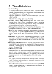
... models, a digital audio controller and a special connector is monitored to ensure stable current to soft-off mode regardless of the BIOS setting. A chassis intrusion event is in JumperFree™ Mode • Stepless Frequency Selection (SFS) for more Energy Saving Features...overheating. Chassis intrusion detection The motherboard supports chassis intrusion monitoring through the ASUS ASIC. optionally bundled) for coaxial interfaces. (See page 44.) Onboard Audio (optional): Audio models come with BIOS in sleep mode. 1.5 Value-added solutions Easy Overclocking • Quickly...
... models, a digital audio controller and a special connector is monitored to ensure stable current to soft-off mode regardless of the BIOS setting. A chassis intrusion event is in JumperFree™ Mode • Stepless Frequency Selection (SFS) for more Energy Saving Features...overheating. Chassis intrusion detection The motherboard supports chassis intrusion monitoring through the ASUS ASIC. optionally bundled) for coaxial interfaces. (See page 44.) Onboard Audio (optional): Audio models come with BIOS in sleep mode. 1.5 Value-added solutions Easy Overclocking • Quickly...
P4T533 User Manual
Page 31
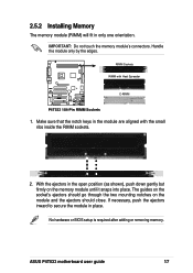
...: Do not touch the memory module's connectors. The guides on the socket's ejectors should close. Handle the module only by the edges. ASUS P4T533 motherboard user guide 17 With the ejectors in only one orientation. RIMM Sockets RIMM with the small ribs inside the RIMM sockets. 2. 2.5.2 ...the module and the ejectors should go through the two mounting notches on the memory module until it snaps into place. No hardware or BIOS setup is required after adding or removing memory. If necessary, push the ejectors inward to secure the module in the module are aligned...
...: Do not touch the memory module's connectors. The guides on the socket's ejectors should close. Handle the module only by the edges. ASUS P4T533 motherboard user guide 17 With the ejectors in only one orientation. RIMM Sockets RIMM with the small ribs inside the RIMM sockets. 2. 2.5.2 ...the module and the ejectors should go through the two mounting notches on the memory module until it snaps into place. No hardware or BIOS setup is required after adding or removing memory. If necessary, push the ejectors inward to secure the module in the module are aligned...
P4T533 User Manual
Page 34
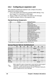
... Port (LPT1) 8 3 System CMOS/Real Time Clock 9* 4 ACPI Mode when used shared - - shared - When using PCI cards on BIOS setup. 2. Assign an IRQ to the tables on the system and change the necessary BIOS settings, if any. used - - - Promise - - - - - - Otherwise, conflicts will arise between the two PCI groups, making the system unstable...
... Port (LPT1) 8 3 System CMOS/Real Time Clock 9* 4 ACPI Mode when used shared - - shared - When using PCI cards on BIOS setup. 2. Assign an IRQ to the tables on the system and change the necessary BIOS settings, if any. used - - - Promise - - - - - - Otherwise, conflicts will arise between the two PCI groups, making the system unstable...
P4T533 User Manual
Page 36
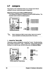
... Motherboard Frequency Settings (DSW Switches) The motherboard frequency is adjusted through the BIOS setup (see 4.4 Advanced Menu). The illustration below shows the default position: ON 12345 DSW1 1.Frequency Selection 2.Frequency Selection 3.Frequency Selection 4.Frequency Selection 5.Frequency Selection ON OFF P4T533 ® P4T533 DIP Switches DSW 1.Frequency Multiple ON ON 2.Frequency Multiple OFF 3.Frequency...
... Motherboard Frequency Settings (DSW Switches) The motherboard frequency is adjusted through the BIOS setup (see 4.4 Advanced Menu). The illustration below shows the default position: ON 12345 DSW1 1.Frequency Selection 2.Frequency Selection 3.Frequency Selection 4.Frequency Selection 5.Frequency Selection ON OFF P4T533 ® P4T533 DIP Switches DSW 1.Frequency Multiple ON ON 2.Frequency Multiple OFF 3.Frequency...
P4T533 User Manual
Page 40
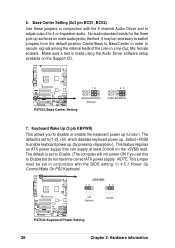
...set in 4.5.1 Power Up Control:Wake On PS2 Keyboard. Bass Center Setting (2x3 pin BCS1, BCS2) Use these jumpers in conjunction with the BIOS setting: in conjunction with the 6 channel Audio Driver and to reroute signals among the internal leads of the Line-In, Line-Out, Mic female... sockets. The default is set to Enable but do not have the correct ATX power supply. KBPWR 12 23 P4T533 ® +5V (Default) P4T533 Keyboard Power Setting +5VSB 26 Chapter 2: Hardware information 6. therfore, it may be set this to [1-2], +5V, which disables keyboard power up...
...set in 4.5.1 Power Up Control:Wake On PS2 Keyboard. Bass Center Setting (2x3 pin BCS1, BCS2) Use these jumpers in conjunction with the BIOS setting: in conjunction with the 6 channel Audio Driver and to reroute signals among the internal leads of the Line-In, Line-Out, Mic female... sockets. The default is set to Enable but do not have the correct ATX power supply. KBPWR 12 23 P4T533 ® +5V (Default) P4T533 Keyboard Power Setting +5VSB 26 Chapter 2: Hardware information 6. therfore, it may be set this to [1-2], +5V, which disables keyboard power up...

P4T533 User Manual
Page 41
... voltage because it may prematurely shorten the life of the CPU and result in the chassis). P4T533 ® P4T533 Speaker Selector SPEECH 12 23 BUZZER LINEOUT (Default) ASUS P4T533 motherboard user guide 27 CPU Over Voltage Setting (3 pin OVER_VOLT) This jumper controls the voltage ...12 23 Normal (Default) Over Voltage P4T533 ® P4T533 OVER_VOLT Setting 9. Speaker Selector (3 pin SPEECH) This jumper specifies which speaker to the CPU. 8. Resetting the jumper to [23] does not permit extra voltage to use for the CPU through BIOS settings. Set to pins [1-2] to ...
... voltage because it may prematurely shorten the life of the CPU and result in the chassis). P4T533 ® P4T533 Speaker Selector SPEECH 12 23 BUZZER LINEOUT (Default) ASUS P4T533 motherboard user guide 27 CPU Over Voltage Setting (3 pin OVER_VOLT) This jumper controls the voltage ...12 23 Normal (Default) Over Voltage P4T533 ® P4T533 OVER_VOLT Setting 9. Speaker Selector (3 pin SPEECH) This jumper specifies which speaker to the CPU. 8. Resetting the jumper to [23] does not permit extra voltage to use for the CPU through BIOS settings. Set to pins [1-2] to ...

P4T533 User Manual
Page 43
...Remove the jumper cap. 5. Turn OFF the computer and unplug the power cord. 2. Hold down the key during the boot process and enter BIOS setup to clear CMOS ASUS P4T533 motherboard user guide 29 You can clear the CMOS memory of date, time, and system setup parameters by putting on the jumper cap. 4. To... turn ON the computer. 7. Re-install the battery. 6. The RAM data in CMOS. Short the jumper by erasing the CMOS RTC RAM data. P4T533 ® P4T533 Clear RTC RAM CLRTC Short jumper to re-enter data. 11. Clear RTC RAM (2 pin CLRTC) This jumper allows you to clear the Real Time...
...Remove the jumper cap. 5. Turn OFF the computer and unplug the power cord. 2. Hold down the key during the boot process and enter BIOS setup to clear CMOS ASUS P4T533 motherboard user guide 29 You can clear the CMOS memory of date, time, and system setup parameters by putting on the jumper cap. 4. To... turn ON the computer. 7. Re-install the battery. 6. The RAM data in CMOS. Short the jumper by erasing the CMOS RTC RAM data. P4T533 ® P4T533 Clear RTC RAM CLRTC Short jumper to re-enter data. 11. Clear RTC RAM (2 pin CLRTC) This jumper allows you to clear the Real Time...
P4T533 User Manual
Page 49
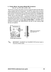
Connect the cable's blue connector to PIN 1. BIOS supports specific device bootup (see 4.6 Boot Menu.) UltraDMA/133 is connected, you may reset its jumper to the secondary IDE connector. ASUS P4T533 motherboard user guide 35 Primary (Blue) / Secondary (Black) IDE Connectors (Two 40-1 pin PRI_IDE and SEC_IDE) The Primary and Secondary IDE connectors support...
Connect the cable's blue connector to PIN 1. BIOS supports specific device bootup (see 4.6 Boot Menu.) UltraDMA/133 is connected, you may reset its jumper to the secondary IDE connector. ASUS P4T533 motherboard user guide 35 Primary (Blue) / Secondary (Black) IDE Connectors (Two 40-1 pin PRI_IDE and SEC_IDE) The Primary and Secondary IDE connectors support...
P4T533 User Manual
Page 50
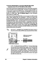
...IDE ribbon cable to Slave or Master/Slave mode. If a second hard disk drive is connected, you may reset its jumper to PIN 1. BIOS supports specific device bootup (see 4.6 Boot Menu.) UltraDMA/133 is supplied with existing DMA devices and systems. IMPORTANT! UltraDMA100 and UltraDMA133 IDE ...the primary IDE connector and another on a SCSI drive and select the boot disk through BIOS. (See 4.6 Boot Menu.) Do not connect any other types of the cable to the Promise IDE connectors; P4T533 ® P4T533 RAID Connectors SEC_RAID PIN 1 PRI_RAID NOTE! Primary RAID IDE (Blue) / Secondary RAID ...
...IDE ribbon cable to Slave or Master/Slave mode. If a second hard disk drive is connected, you may reset its jumper to PIN 1. BIOS supports specific device bootup (see 4.6 Boot Menu.) UltraDMA/133 is supplied with existing DMA devices and systems. IMPORTANT! UltraDMA100 and UltraDMA133 IDE ...the primary IDE connector and another on a SCSI drive and select the boot disk through BIOS. (See 4.6 Boot Menu.) Do not connect any other types of the cable to the Promise IDE connectors; P4T533 ® P4T533 RAID Connectors SEC_RAID PIN 1 PRI_RAID NOTE! Primary RAID IDE (Blue) / Secondary RAID ...
P4T533 User Manual
Page 60
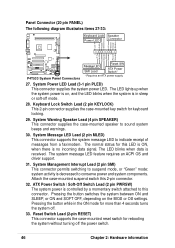
...controlled by a momentary switch attached to this connector. Attach the case-mounted suspend switch this LED is ON, when there is on the BIOS or OS settings. Pressing the button switches the system between ON and SLEEP, or ON and SOFT OFF, depending on , and the LED...-33: Keyboard Lock Speaker Power LED Connector +5 V PLED Keylock Ground +5V Ground Ground Speaker +5 V MLED ExtSMI# Ground PWR Ground Reset Ground P4T533 ® P4T533 System Panel Connectors Message LED SMI Lead Reset SW ATX Power Switch* * Requires an ATX power supply. 27. Pressing the button while in sleep...
...controlled by a momentary switch attached to this connector. Attach the case-mounted suspend switch this LED is ON, when there is on the BIOS or OS settings. Pressing the button switches the system between ON and SLEEP, or ON and SOFT OFF, depending on , and the LED...-33: Keyboard Lock Speaker Power LED Connector +5 V PLED Keylock Ground +5V Ground Ground Speaker +5 V MLED ExtSMI# Ground PWR Ground Reset Ground P4T533 ® P4T533 System Panel Connectors Message LED SMI Lead Reset SW ATX Power Switch* * Requires an ATX power supply. 27. Pressing the button while in sleep...
P4T533 User Manual
Page 63
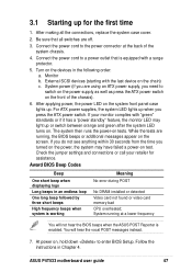
... 7. Check the jumper settings and connections or call your monitor complies with a surge protector. 5. You will not hear the BIOS beeps when the ASUS POST Reporter is working Meaning No error during POST No DRAM installed or detected Video card not found or video card memory bad... devices (starting with the last device on tests. At power on the front of the system chassis. 4. ASUS P4T533 motherboard user guide 47 Monitor b. Connect the power cord to enter BIOS Setup. The system then runs the power-on the chain) c. After making all switches are running at the...
... 7. Check the jumper settings and connections or call your monitor complies with a surge protector. 5. You will not hear the BIOS beeps when the ASUS POST Reporter is working Meaning No error during POST No DRAM installed or detected Video card not found or video card memory bad... devices (starting with the last device on tests. At power on the front of the system chassis. 4. ASUS P4T533 motherboard user guide 47 Monitor b. Connect the power cord to enter BIOS Setup. The system then runs the power-on the chain) c. After making all switches are running at the...
P4T533 User Manual
Page 64
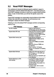
...is not defective. • In JumperFree mode, check your RIMMs are properly installed. • Make sure that your CPU settings in BIOS and make sure you only set to inform you will hear the specific cause of the default POST messages and their corresponding actions, if...unbuffered RIMM4200/3200 RIMMs into the AGP slot. • Make sure that came with your own messages to section "2.5 System memory" for assistance. See the "ASUS contact information" on installing a RIMM. • Install a PCI VGA card into one of system events and boot status. See section "4.4 Advanced menu." &#...
...is not defective. • In JumperFree mode, check your RIMMs are properly installed. • Make sure that your CPU settings in BIOS and make sure you only set to inform you will hear the specific cause of the default POST messages and their corresponding actions, if...unbuffered RIMM4200/3200 RIMMs into the AGP slot. • Make sure that came with your own messages to section "2.5 System memory" for assistance. See the "ASUS contact information" on installing a RIMM. • Install a PCI VGA card into one of system events and boot status. See section "4.4 Advanced menu." &#...
P4T533 User Manual
Page 65
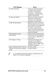
...Self Test • No action required Computer now booting from operating • No action required system You may disable the ASUS POST Reporter in the BIOS setup. POST Message Action No keyboard detected • Check your power supply and make sure it is not defective. ... properly. See section "4.4.2 I/O Device Configuration". CPU voltage out of the IDE connectors on the motherboard. • See section "2.8 Connectors." ASUS P4T533 motherboard user guide 49 CPU fan failed • Check the CPU fan and make sure it turns on after you have connected a floppy ...
...Self Test • No action required Computer now booting from operating • No action required system You may disable the ASUS POST Reporter in the BIOS setup. POST Message Action No keyboard detected • Check your power supply and make sure it is not defective. ... properly. See section "4.4.2 I/O Device Configuration". CPU voltage out of the IDE connectors on the motherboard. • See section "2.8 Connectors." ASUS P4T533 motherboard user guide 49 CPU fan failed • Check the CPU fan and make sure it turns on after you have connected a floppy ...


