Motherboard DIY Troubleshooting Guide
Page 68
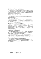
CPU/Memory Frequency Ratio [Auto] MHz CPU CPU/PCI Frequency [Auto] [1:1] [3:4][3:5] CPU Level 2 Cache [Enabled] CPU [Disabled] [Enabled] BIOS Update [Enabled] BIOS CPU BIOS CPU [Disabled] [Enabled] PS/2 Mouse Function Control [Auto] [Auto] PS/2 BIOS IRQ 12 PS/2 [Enabled] PS/2 BIOS IRQ 12 [Enabled] [Auto] IRQ 12 PS/2 USB Legacy Support [Auto] [Auto] USB USB USB 1.1 USB ] [Enabled] [Auto] [Disabled] USB USB [Disabled OS/2 Onboard Memory > 64M [Disabled] OS/2 [Enabled] [Disabled] [Enabled] 64MB [Disabled] 4-16 BIOS
CPU/Memory Frequency Ratio [Auto] MHz CPU CPU/PCI Frequency [Auto] [1:1] [3:4][3:5] CPU Level 2 Cache [Enabled] CPU [Disabled] [Enabled] BIOS Update [Enabled] BIOS CPU BIOS CPU [Disabled] [Enabled] PS/2 Mouse Function Control [Auto] [Auto] PS/2 BIOS IRQ 12 PS/2 [Enabled] PS/2 BIOS IRQ 12 [Enabled] [Auto] IRQ 12 PS/2 USB Legacy Support [Auto] [Auto] USB USB USB 1.1 USB ] [Enabled] [Auto] [Disabled] USB USB [Disabled OS/2 Onboard Memory > 64M [Disabled] OS/2 [Enabled] [Disabled] [Enabled] 64MB [Disabled] 4-16 BIOS

Motherboard DIY Troubleshooting Guide
Page 81
Enter Power setup menu for details : Press F1 to continue, DEL to enter SETUP F1 DEL P4SGL-VM 4-29 4.5.2 Hardware Monitor MB Temperature [xxxC/xxxF] CPU Temperature [xxxC/xxxF] CPU Fan Speed [xxxxRPM] or [N/A] Chassis Fan Speed [xxxxRPM] or [N/A] RPM Rotations Per Minute VCORE Voltage, +3.3V Voltage, +5V Voltage, +12V Voltage CPU : Hardware Monitor found an error.
Enter Power setup menu for details : Press F1 to continue, DEL to enter SETUP F1 DEL P4SGL-VM 4-29 4.5.2 Hardware Monitor MB Temperature [xxxC/xxxF] CPU Temperature [xxxC/xxxF] CPU Fan Speed [xxxxRPM] or [N/A] Chassis Fan Speed [xxxxRPM] or [N/A] RPM Rotations Per Minute VCORE Voltage, +3.3V Voltage, +5V Voltage, +12V Voltage CPU : Hardware Monitor found an error.

P4SGL-VM User Manual
Page 3
... viii How this guide is organized viii Conventions used in this guide ix Where to find more information ix ASUS contact information x Chapter 1: Product introduction 1-1 1.1 Welcome 1-1 1.2 Package contents 1-1 1.3 Special features 1-2 ... 2-1 2.1.2 Screw holes 2-1 2.2 Motherboard layout 2-2 2.3 Before you proceed 2-3 2.4 Central Processing Unit (CPU 2-4 2.4.1 Overview 2-4 2.4.2 Installing the CPU 2-5 2.4.3 Installing the heatsink and fan 2-7 2.4.4 Connecting the CPU fan cable 2-9 2.5 System memory 2-10 2.5.1 Overview 2-10 2.5.2 Memory configurations 2-11 2.5.3 Installing a ...
... viii How this guide is organized viii Conventions used in this guide ix Where to find more information ix ASUS contact information x Chapter 1: Product introduction 1-1 1.1 Welcome 1-1 1.2 Package contents 1-1 1.3 Special features 1-2 ... 2-1 2.1.2 Screw holes 2-1 2.2 Motherboard layout 2-2 2.3 Before you proceed 2-3 2.4 Central Processing Unit (CPU 2-4 2.4.1 Overview 2-4 2.4.2 Installing the CPU 2-5 2.4.3 Installing the heatsink and fan 2-7 2.4.4 Connecting the CPU fan cable 2-9 2.5 System memory 2-10 2.5.1 Overview 2-10 2.5.2 Memory configurations 2-11 2.5.3 Installing a ...
P4SGL-VM User Manual
Page 15
1.3.2 Value-added solutions Overclocking The P4SGL-VM overclocking features: • adjustable CPU frequency multiple in BIOS using the ASUS JumperFree™ solution • adjustable FSB/MEM frequency ratio • Stepless Frequency Selection (SFS) for fine-tuning system bus frequency from 100MHz up to 166MHz at 1MHz increments • optimized system performance through BIOS built-in optimization mode ASUS P4SGL-VM motherboard user guide 1-3
1.3.2 Value-added solutions Overclocking The P4SGL-VM overclocking features: • adjustable CPU frequency multiple in BIOS using the ASUS JumperFree™ solution • adjustable FSB/MEM frequency ratio • Stepless Frequency Selection (SFS) for fine-tuning system bus frequency from 100MHz up to 166MHz at 1MHz increments • optimized system performance through BIOS built-in optimization mode ASUS P4SGL-VM motherboard user guide 1-3

P4SGL-VM User Manual
Page 16
CPU socket 3. North Bridge controller 4. ATX power connector 5. South Bridge ...may damage the board and its physical configuration and available features to Chapter 2 for a brief description of the P4SGL-VM motherboard as pointed out in the picture on page 1-5. 1. LAN PHY (on the motherboard jumpers and connectors. ... installation and future upgrades. A sufficient knowledge of the motherboard specifications will also help you install the P4SGL-VM motherboard, familiarize yourself with its components. 1.4.1 Motherboard components The following are the major components of each...
CPU socket 3. North Bridge controller 4. ATX power connector 5. South Bridge ...may damage the board and its physical configuration and available features to Chapter 2 for a brief description of the P4SGL-VM motherboard as pointed out in the picture on page 1-5. 1. LAN PHY (on the motherboard jumpers and connectors. ... installation and future upgrades. A sufficient knowledge of the motherboard specifications will also help you install the P4SGL-VM motherboard, familiarize yourself with its components. 1.4.1 Motherboard components The following are the major components of each...
P4SGL-VM User Manual
Page 18
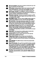
This power connector connects the 4-pin 12V plug from the ATX 12V power supply. 2 CPU socket. This SiS650GL controller integrates a high performance host interface for the floppy disk drive. The power supply must have at least 1A on the +5V ... master IDE connectors support up to the board. 10 Floppy disk connector. Both the primary (blue) and secondary (black) connectors are slotted to PCI Bridge. 8 ASUS ASIC. A 478-pin surface mount, Zero Insertion Force (ZIF) socket called mPGA478. This 20-pin connector connects to four Ultra DMA/133/100/66, PIO...
This power connector connects the 4-pin 12V plug from the ATX 12V power supply. 2 CPU socket. This SiS650GL controller integrates a high performance host interface for the floppy disk drive. The power supply must have at least 1A on the +5V ... master IDE connectors support up to the board. 10 Floppy disk connector. Both the primary (blue) and secondary (black) connectors are slotted to PCI Bridge. 8 ASUS ASIC. A 478-pin surface mount, Zero Insertion Force (ZIF) socket called mPGA478. This 20-pin connector connects to four Ultra DMA/133/100/66, PIO...

P4SGL-VM User Manual
Page 26
... higher processor frequencies, faster execution of integer instructions, and a data transfer rate of the CPU into the socket may bend the pins and severely damage the CPU! 2-4 Chapter 2: Hardware information The Intel NetBurst micro-architecture features the hyper-pipelined technology, rapid... execution engine, 400MHz system bus, and execution trace cache. 2.4 Central Processing Unit (CPU) 2.4.1 Overview The motherboard comes with a surface mount 478-pin Zero Insertion Force (ZIF) socket. Gold Mark Note in the 478...
... higher processor frequencies, faster execution of integer instructions, and a data transfer rate of the CPU into the socket may bend the pins and severely damage the CPU! 2-4 Chapter 2: Hardware information The Intel NetBurst micro-architecture features the hyper-pipelined technology, rapid... execution engine, 400MHz system bus, and execution trace cache. 2.4 Central Processing Unit (CPU) 2.4.1 Overview The motherboard comes with a surface mount 478-pin Zero Insertion Force (ZIF) socket. Gold Mark Note in the 478...

P4SGL-VM User Manual
Page 27
2.4.2 Installing the CPU Follow these steps to 90°-100° angle, otherwise the CPU does not fit in completely. Socket Lever 90 - 100 Make sure that the socket lever is lifted up to a 90°-100° angle. Unlock the socket by pressing the lever sideways, then lift it up to install a CPU. 1. ASUS P4SGL-VM motherboard user guide 2-5 Locate the 478-pin ZIF socket on the motherboard. 2.
2.4.2 Installing the CPU Follow these steps to 90°-100° angle, otherwise the CPU does not fit in completely. Socket Lever 90 - 100 Make sure that the socket lever is lifted up to a 90°-100° angle. Unlock the socket by pressing the lever sideways, then lift it up to install a CPU. 1. ASUS P4SGL-VM motherboard user guide 2-5 Locate the 478-pin ZIF socket on the motherboard. 2.

P4SGL-VM User Manual
Page 28
The CPU fits only in place, press it is in one correct orientation. DO NOT force the CPU into the socket until it fits in place. When the CPU is locked. 2-6 Chapter 2: Hardware information Position the CPU above the socket such that it firmly on the side tab to indicate that its marked corner matches the base of the socket lever. 4. The lever clicks on the socket while you push down the socket lever to prevent bending the pins and damaging the CPU! Carefully insert the CPU into the socket to secure the CPU. Gold Mark 5. 3.
The CPU fits only in place, press it is in one correct orientation. DO NOT force the CPU into the socket until it fits in place. When the CPU is locked. 2-6 Chapter 2: Hardware information Position the CPU above the socket such that it firmly on the side tab to indicate that its marked corner matches the base of the socket lever. 4. The lever clicks on the socket while you push down the socket lever to prevent bending the pins and damaging the CPU! Carefully insert the CPU into the socket to secure the CPU. Gold Mark 5. 3.

P4SGL-VM User Manual
Page 29
... The retention module base is already installed on top of the installed CPU, making sure that you use only Intel certified heatsink and fan. Place the heatsink on the motherboard upon purchase. ASUS P4SGL-VM motherboard user guide 2-7 If the instructions in this section do not have... to install the CPU heatsink and fan. 1. In case you buy a CPU separately, make sure that the heatsink fits properly on the retention...
... The retention module base is already installed on top of the installed CPU, making sure that you use only Intel certified heatsink and fan. Place the heatsink on the motherboard upon purchase. ASUS P4SGL-VM motherboard user guide 2-7 If the instructions in this section do not have... to install the CPU heatsink and fan. 1. In case you buy a CPU separately, make sure that the heatsink fits properly on the retention...

P4SGL-VM User Manual
Page 31
ASUS P4SGL-VM motherboard user guide 2-9 When secure, the retention locks should point to opposite directions. 2.4.4 Connecting the CPU fan cable When the fan, heatsink, and the retention mechanism are in place, connect the CPU fan cable to plug this connector. Hardware monitoring errors may occur if you fail to the connector on the retention mechanism to secure the heatsink and fan to connect the CPU fan connector! 3. Push down the locks on the motherboard labeled CPUFAN1. CPU Fan Connector (CPUFAN1) Don't forget to the module base.
ASUS P4SGL-VM motherboard user guide 2-9 When secure, the retention locks should point to opposite directions. 2.4.4 Connecting the CPU fan cable When the fan, heatsink, and the retention mechanism are in place, connect the CPU fan cable to plug this connector. Hardware monitoring errors may occur if you fail to the connector on the retention mechanism to secure the heatsink and fan to connect the CPU fan connector! 3. Push down the locks on the motherboard labeled CPUFAN1. CPU Fan Connector (CPUFAN1) Don't forget to the module base.

P4SGL-VM User Manual
Page 43
...the floppy ribbon cable to PIN 1. ® PIN 1 P4SGL-VM Floppy Disk Drive Connector 4. CHASFAN1 P4SGL-VM GND +12V Rotation CPUFAN1 GND +12V Rotation SPSFAN1 ® GND +12V NC P4SGL-VM 12-Volt Cooling Fan Power ASUS P4SGL-VM motherboard user guide 2-21 Lack of sufficient air flow within ...the system may vary depending on the fan manufacturer. Floppy disk drive connector (34-1 pin FLOPPY) This connector supports the provided floppy drive ribbon cable. CPU and...
...the floppy ribbon cable to PIN 1. ® PIN 1 P4SGL-VM Floppy Disk Drive Connector 4. CHASFAN1 P4SGL-VM GND +12V Rotation CPUFAN1 GND +12V Rotation SPSFAN1 ® GND +12V NC P4SGL-VM 12-Volt Cooling Fan Power ASUS P4SGL-VM motherboard user guide 2-21 Lack of sufficient air flow within ...the system may vary depending on the fan manufacturer. Floppy disk drive connector (34-1 pin FLOPPY) This connector supports the provided floppy drive ribbon cable. CPU and...
P4SGL-VM User Manual
Page 44
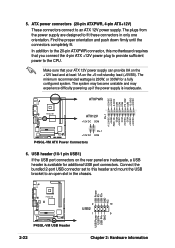
In addition to the 20-pin ATXPWR connector, this header and mount the USB bracket to the CPU. USB header (10-1 pin USB1) If the USB port connectors on the +5-volt standby lead (+5VSB). The minimum recommended wattage is available for a fully configured ... +12V lead and at least 1A on the rear panel are designed to an ATX 12V power supply. USB Power USB P3USB P3+ GND NC P4SGL-VM ® P4SGL-VM USB Header 2-22 2 10 USB2 1 9 USB Power USB P4USB P4+ GND Chapter 2: Hardware information 5. The plugs from the power supply are inadequate, a USB header...
In addition to the 20-pin ATXPWR connector, this header and mount the USB bracket to the CPU. USB header (10-1 pin USB1) If the USB port connectors on the +5-volt standby lead (+5VSB). The minimum recommended wattage is available for a fully configured ... +12V lead and at least 1A on the rear panel are designed to an ATX 12V power supply. USB Power USB P3USB P3+ GND NC P4SGL-VM ® P4SGL-VM USB Header 2-22 2 10 USB2 1 9 USB Power USB P4USB P4+ GND Chapter 2: Hardware information 5. The plugs from the power supply are inadequate, a USB header...
P4SGL-VM User Manual
Page 53
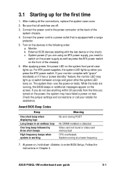
Be sure that is working Meaning No error during POST No DRAM installed or detected Video card not found or video card memory bad CPU overheated; Turn on the system front panel case lights up. After applying power, the power LED on the devices in the following ... supply, you press the ATX power switch. System running , the BIOS beeps or additional messages appear on the front of the system chassis. 4. ASUS P4SGL-VM motherboard user guide 3-1 3.1 Starting up for assistance. Monitor b. Connect the power cord to enter BIOS Setup. Check the jumper settings and connections or...
Be sure that is working Meaning No error during POST No DRAM installed or detected Video card not found or video card memory bad CPU overheated; Turn on the system front panel case lights up. After applying power, the power LED on the devices in the following ... supply, you press the ATX power switch. System running , the BIOS beeps or additional messages appear on the front of the system chassis. 4. ASUS P4SGL-VM motherboard user guide 3-1 3.1 Starting up for assistance. Monitor b. Connect the power cord to enter BIOS Setup. Check the jumper settings and connections or...
P4SGL-VM User Manual
Page 71
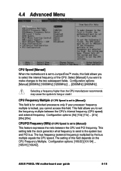
... the internal frequency of this field. This setting tells the clock generator what frequency to send to hang or crash! CPU Frequency Multiple (if CPU Speed is set to set the frequency multiple between the CPU and PCI frequency. ASUS P4SGL-VM motherboard user guide 4-15 Configuration options: [8x] [10x] [11x] ... [21x] [22x] [23x]. 4.4 Advanced Menu...
... the internal frequency of this field. This setting tells the clock generator what frequency to send to hang or crash! CPU Frequency Multiple (if CPU Speed is set to set the frequency multiple between the CPU and PCI frequency. ASUS P4SGL-VM motherboard user guide 4-15 Configuration options: [8x] [10x] [11x] ... [21x] [22x] [23x]. 4.4 Advanced Menu...
P4SGL-VM User Manual
Page 72
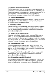
...Chapter 4: BIOS Setup The options that appear in cache. Configuration options: [Auto] [1:1] [3:4] [3:5] (The configuration options vary according to the CPU frequency.) CPU Level 2 Cache [Enabled] These fields allow you need to set this option to detect a USB device at startup. Configuration options: [Disabled]...to [Disabled], the USB controller legacy mode is detected, the BIOS assigns IRQ12 to detect a PS/2 mouse at startup. CPU/Memory Frequency Ratio [Auto] This field determines whether the memory clock frequency is detected at startup. Configuration options: [Disabled]...
...Chapter 4: BIOS Setup The options that appear in cache. Configuration options: [Auto] [1:1] [3:4] [3:5] (The configuration options vary according to the CPU frequency.) CPU Level 2 Cache [Enabled] These fields allow you need to set this option to detect a USB device at startup. Configuration options: [Disabled]...to [Disabled], the USB controller legacy mode is detected, the BIOS assigns IRQ12 to detect a PS/2 mouse at startup. CPU/Memory Frequency Ratio [Auto] This field determines whether the memory clock frequency is detected at startup. Configuration options: [Disabled]...

P4SGL-VM User Manual
Page 85
...hardware monitor automatically detects the voltage output through the onboard voltage regulators and show N/A. ASUS P4SGL-VM motherboard user guide 4-29 CPU Fan Speed [xxxxRPM] or N/A Chassis Fan Speed [xxxxRPM] or N/A The onboard hardware monitor automatically detects the CPU and chassis fan speeds in rotations per minute (RPM). You will show the ...be prompted to "Press F1 to continue or DEL to the fan connectors on these fields. 4.5.2 Hardware Monitor MB Temperature [xxxC/xxxF] CPU Temperature [xxxC/xxxF] The onboard hardware monitor automatically detects the MB (motherboard) and...
...hardware monitor automatically detects the voltage output through the onboard voltage regulators and show N/A. ASUS P4SGL-VM motherboard user guide 4-29 CPU Fan Speed [xxxxRPM] or N/A Chassis Fan Speed [xxxxRPM] or N/A The onboard hardware monitor automatically detects the CPU and chassis fan speeds in rotations per minute (RPM). You will show the ...be prompted to "Press F1 to continue or DEL to the fan connectors on these fields. 4.5.2 Hardware Monitor MB Temperature [xxxC/xxxF] CPU Temperature [xxxC/xxxF] The onboard hardware monitor automatically detects the MB (motherboard) and...
P4SGL-VM User Manual
Page 95
...The above PC-cillin version supports Windows XP operating system and maintains backward compatibility with Windows 95. ASUS PC Probe This smart utility monitors the fan speed, CPU temperature, and system voltages, and alerts you keep your computer at a healthy operating condition. PC...using the ASUS Update, make sure that the SiS Display Driver is installed first. 5.2.3 Software and drivers description The menu lists the drivers and applications that are available for this item to install it. SiS 650/651 Display Driver Click this motherboard. ASUS P4SGL-VM motherboard ...
...The above PC-cillin version supports Windows XP operating system and maintains backward compatibility with Windows 95. ASUS PC Probe This smart utility monitors the fan speed, CPU temperature, and system voltages, and alerts you keep your computer at a healthy operating condition. PC...using the ASUS Update, make sure that the SiS Display Driver is installed first. 5.2.3 Software and drivers description The menu lists the drivers and applications that are available for this item to install it. SiS 650/651 Display Driver Click this motherboard. ASUS P4SGL-VM motherboard ...

P4SGL-VM User Manual
Page 99
...will allow you to select whether or not to Programs, and then ASUS Utility, and then click Probe Vx.xx. ASUS P4GL-VM motherboard user guide 5-7 It also has a utility that ASUS PC Probe is a convenient utility to continuously monitor your computer system...'s vital components, such as hard disk space, memory usage, and CPU type, CPU speed, and internal/external frequencies through the DMI Explorer. 5.4.1 Starting ASUS PC Probe When ASUS...
...will allow you to select whether or not to Programs, and then ASUS Utility, and then click Probe Vx.xx. ASUS P4GL-VM motherboard user guide 5-7 It also has a utility that ASUS PC Probe is a convenient utility to continuously monitor your computer system...'s vital components, such as hard disk space, memory usage, and CPU type, CPU speed, and internal/external frequencies through the DMI Explorer. 5.4.1 Starting ASUS PC Probe When ASUS...

P4SGL-VM User Manual
Page 101
... a certain component of the PC's hard disk drives and the file allocation table or file system used. ASUS P4GL-VM motherboard user guide 5-9 When When CPU Overheated is selected, the CPU cooling system is enabled whenever the CPU temperature reaches the threshold value. Information Hard Drives Shows the used and free space of your PC...
... a certain component of the PC's hard disk drives and the file allocation table or file system used. ASUS P4GL-VM motherboard user guide 5-9 When When CPU Overheated is selected, the CPU cooling system is enabled whenever the CPU temperature reaches the threshold value. Information Hard Drives Shows the used and free space of your PC...


