
P4S333 English Manual
Page 8
About this document. viii It includes brief descriptions of the special attributes of the P4S333 motherboard. How this document. • Index This part contains an alphabetical list of the switches, jumpers, and connectors on the motherboard. • ... the new technology it supports. • Chapter 2: Hardware information This chapter lists the hardware setup procedures that you need when installing the ASUS P4S333 motherboard. It includes description of the topics found in this guide This user guide contains the information you have to change system settings through ...
About this document. viii It includes brief descriptions of the special attributes of the P4S333 motherboard. How this document. • Index This part contains an alphabetical list of the switches, jumpers, and connectors on the motherboard. • ... the new technology it supports. • Chapter 2: Hardware information This chapter lists the hardware setup procedures that you need when installing the ASUS P4S333 motherboard. It includes description of the topics found in this guide This user guide contains the information you have to change system settings through ...

P4S333 English Manual
Page 12
ASUS P4S333 motherboard
ASUS P4S333 motherboard

P4S333 English Manual
Page 13
... transfers using the ATA100 protocol, and AC '97-compliant audio features, the P4S333 is damaged or missing, contact your package with the SiS 645 chipset to get ahead in ) ASUS P4S333 support CD ASUS 2-port USB 1.1 module I/O plate (for LAN models only) 80-conductor ...Northwood Processor coupled with the list below. 1.2 Package contents Check your P4S333 package for the following items. ASUS P4S333 motherboard (ATX form factor: 12.0-in x 8.6-in the world of ASUS quality motherboards! 1.1 Welcome! The ASUS P4S333 motherboard delivers a host of new features and latest technology making it ...
... transfers using the ATA100 protocol, and AC '97-compliant audio features, the P4S333 is damaged or missing, contact your package with the SiS 645 chipset to get ahead in ) ASUS P4S333 support CD ASUS 2-port USB 1.1 module I/O plate (for LAN models only) 80-conductor ...Northwood Processor coupled with the list below. 1.2 Package contents Check your P4S333 package for the following items. ASUS P4S333 motherboard (ATX form factor: 12.0-in x 8.6-in the world of ASUS quality motherboards! 1.1 Welcome! The ASUS P4S333 motherboard delivers a host of new features and latest technology making it ...

P4S333 English Manual
Page 15
...-capacity storage through the sophisticated SD and MS devices. 1.3.2 Value-added solutions Overclocking The P4S333 overclocking features: • adjustable CPU frequency multiple in BIOS using the ASUS JumperFree™ solution • adjustable FSB/MEM frequency ratio • Stepless Frequency Selection...language support. The bundled Winbond Voice Editor software allows you of the system boot status and causes of system status. ASUS P4S333 motherboard user guide 1-3 The Smart Card Reader promotes cutting-edge technology featuring increased security for Smart Card, Secure Digital (...
...-capacity storage through the sophisticated SD and MS devices. 1.3.2 Value-added solutions Overclocking The P4S333 overclocking features: • adjustable CPU frequency multiple in BIOS using the ASUS JumperFree™ solution • adjustable FSB/MEM frequency ratio • Stepless Frequency Selection...language support. The bundled Winbond Voice Editor software allows you of the system boot status and causes of system status. ASUS P4S333 motherboard user guide 1-3 The Smart Card Reader promotes cutting-edge technology featuring increased security for Smart Card, Secure Digital (...

P4S333 English Manual
Page 17
1 23 4 56 7 19 18 17 16 15 14 20 21 22 8 9 10 11 13 12 23 29 28 27 ASUS P4S333 motherboard user guide 26 25 24 1-5
1 23 4 56 7 19 18 17 16 15 14 20 21 22 8 9 10 11 13 12 23 29 28 27 ASUS P4S333 motherboard user guide 26 25 24 1-5

P4S333 English Manual
Page 19
.... The chip also supports 24-bit S/PDIF In (0.5~5V) and S/PDIF Out (44.1K and 48K formats) professional digital audio interface. (on audio models only) ASUS P4S333 motherboard user guide 1-7 This Accelerated Graphics Port (AGP) slot supports 1.5V AGP4X mode graphics cards for a 360K/720K/1.44M/ 2.88M floppy disk drive, a multi-mode...
.... The chip also supports 24-bit S/PDIF In (0.5~5V) and S/PDIF Out (44.1K and 48K formats) professional digital audio interface. (on audio models only) ASUS P4S333 motherboard user guide 1-7 This Accelerated Graphics Port (AGP) slot supports 1.5V AGP4X mode graphics cards for a 360K/720K/1.44M/ 2.88M floppy disk drive, a multi-mode...

P4S333 English Manual
Page 22
ASUS P4S333 motherboard
ASUS P4S333 motherboard

P4S333 English Manual
Page 23
... to ensure that the motherboard fits into it into the holes indicated by circles to secure the motherboard to the rear part of the chassis ASUS P4S333 motherboard user guide 2-1 Failure to unplug the power cord before installing or removing the motherboard. Place this side towards the rear of the chassis. 2.1 ...Motherboard installation Before you place it . Make sure to do so may damage the motherboard. Do not overtighten the screws! The P4S333 uses the ATX form factor that measures 12.0 inches x 8.6 inches, a standard fit for most chassis.
... to ensure that the motherboard fits into it into the holes indicated by circles to secure the motherboard to the rear part of the chassis ASUS P4S333 motherboard user guide 2-1 Failure to unplug the power cord before installing or removing the motherboard. Place this side towards the rear of the chassis. 2.1 ...Motherboard installation Before you place it . Make sure to do so may damage the motherboard. Do not overtighten the screws! The P4S333 uses the ATX form factor that measures 12.0 inches x 8.6 inches, a standard fit for most chassis.

P4S333 English Manual
Page 25
... onboard LED (LED1) indicates that the system is detached from the wall socket before handling components to avoid damaging them . 4. P4S333 ® P4S333 Onboard LED LED1 ON Standby Power OFF Powered Off ASUS P4S333 motherboard user guide 2-3 Whenever you uninstall any component. 2. Before you install or remove any component, ensure that the ATX power...
... onboard LED (LED1) indicates that the system is detached from the wall socket before handling components to avoid damaging them . 4. P4S333 ® P4S333 Onboard LED LED1 ON Standby Power OFF Powered Off ASUS P4S333 motherboard user guide 2-3 Whenever you uninstall any component. 2. Before you install or remove any component, ensure that the ATX power...

P4S333 English Manual
Page 27
Unlock the socket by pressing the lever sideways, then lift it up to a 90°-100° angle. Locate the 478-pin ZIF socket on the motherboard. 2. ASUS P4S333 motherboard user guide 2-5 Socket Lever 90 - 100 Make sure that the socket lever is lifted up to 90°-100° angle, otherwise the CPU does not fit in completely. 2.4.2 Installing the CPU Follow these steps to install a CPU. 1.
Unlock the socket by pressing the lever sideways, then lift it up to a 90°-100° angle. Locate the 478-pin ZIF socket on the motherboard. 2. ASUS P4S333 motherboard user guide 2-5 Socket Lever 90 - 100 Make sure that the socket lever is lifted up to 90°-100° angle, otherwise the CPU does not fit in completely. 2.4.2 Installing the CPU Follow these steps to install a CPU. 1.

P4S333 English Manual
Page 29
... separately, make sure that the heatsink fits properly on the motherboard upon purchase. The retention module base is already installed on the retention module base. ASUS P4S333 motherboard user guide 2-7 Follow these steps to ensure optimum thermal condition and performance. You do not match the CPU documentation, follow the latter. CPU Heatsink...
... separately, make sure that the heatsink fits properly on the motherboard upon purchase. The retention module base is already installed on the retention module base. ASUS P4S333 motherboard user guide 2-7 Follow these steps to ensure optimum thermal condition and performance. You do not match the CPU documentation, follow the latter. CPU Heatsink...

P4S333 English Manual
Page 31
Hardware monitoring errors may occur if you fail to the connector on the retention mechanism to secure the heatsink and fan to connect the CPU fan connector! 3. When secure, the retention locks should point to opposite directions. 2.4.4 Connecting the CPU fan cable When the fan, heatsink, and the retention mechanism are in place, connect the CPU fan cable to plug this connector. ASUS P4S333 motherboard user guide 2-9 Push down the locks on the motherboard labeled CPUFAN1. CPU Fan Connector (CPUFAN1) Don't forget to the module base.
Hardware monitoring errors may occur if you fail to the connector on the retention mechanism to secure the heatsink and fan to connect the CPU fan connector! 3. When secure, the retention locks should point to opposite directions. 2.4.4 Connecting the CPU fan cable When the fan, heatsink, and the retention mechanism are in place, connect the CPU fan cable to plug this connector. ASUS P4S333 motherboard user guide 2-9 Push down the locks on the motherboard labeled CPUFAN1. CPU Fan Connector (CPUFAN1) Don't forget to the module base.

P4S333 English Manual
Page 33
...with this motherboard. Other DDR DIMMs manufactured by other vendors may not be suitable for the latest qualified DDR module list. ASUS P4S333 motherboard user guide 2-11 DDR333 DIMM Qualified Vendors List The following combinations to install DDR DIMMs. DIMM Location 184-pin ...= Total system memory (Max. 3GB) = When using PC2700 DDR DIMMs, the motherboard supports up to 2GB system memory. Visit the ASUS website for this motherboard. Vendor Winbond Micron KINGMAX KINGMAX Model W9425GADA-6 MT8VDDT1664AG-335B1 MPMA82D-68KX3 MPM62D-68KX3 Type/Size PC2700/256MB PC2700/128MB ...
...with this motherboard. Other DDR DIMMs manufactured by other vendors may not be suitable for the latest qualified DDR module list. ASUS P4S333 motherboard user guide 2-11 DDR333 DIMM Qualified Vendors List The following combinations to install DDR DIMMs. DIMM Location 184-pin ...= Total system memory (Max. 3GB) = When using PC2700 DDR DIMMs, the motherboard supports up to 2GB system memory. Visit the ASUS website for this motherboard. Vendor Winbond Micron KINGMAX KINGMAX Model W9425GADA-6 MT8VDDT1664AG-335B1 MPMA82D-68KX3 MPM62D-68KX3 Type/Size PC2700/256MB PC2700/128MB ...

P4S333 English Manual
Page 35
... for later use . Replace the system cover. 2.6.2 Configuring an expansion card After physically installing the expansion card, configure the card by adjusting the software settings. 1. ASUS P4S333 motherboard user guide 2-13 Make sure to the card. Turn on the slot. 5. 2.6 Expansion slots In the future, you may cause you physical injury and...
... for later use . Replace the system cover. 2.6.2 Configuring an expansion card After physically installing the expansion card, configure the card by adjusting the software settings. 1. ASUS P4S333 motherboard user guide 2-13 Make sure to the card. Turn on the slot. 5. 2.6 Expansion slots In the future, you may cause you physical injury and...

P4S333 English Manual
Page 37
The following figure shows a LAN card installed on a PCI slot. The PCI slot 6 shares with PCI specifications. If you installed a card into the ACR slot, you may not use the PCI6 slot. 2.6.4 AGP slot This motherboard has an Accelerated Graphics Port (AGP) slot that comply with the ACR slot. 2.6.3 PCI slots There are six 32-bit PCI slots in this motherboard. P4S333 ® P4S333 Accelerated Graphics Port (AGP) ASUS P4S333 motherboard user guide 2-15 The slots support PCI cards such as a LAN card, SCSI card, USB card, and other cards that supports AGP 4X cards.
The following figure shows a LAN card installed on a PCI slot. The PCI slot 6 shares with PCI specifications. If you installed a card into the ACR slot, you may not use the PCI6 slot. 2.6.4 AGP slot This motherboard has an Accelerated Graphics Port (AGP) slot that comply with the ACR slot. 2.6.3 PCI slots There are six 32-bit PCI slots in this motherboard. P4S333 ® P4S333 Accelerated Graphics Port (AGP) ASUS P4S333 motherboard user guide 2-15 The slots support PCI cards such as a LAN card, SCSI card, USB card, and other cards that supports AGP 4X cards.

P4S333 English Manual
Page 39
...JumperFree™ mode (JEN1) This jumper allows you to use the DIP switches. ASUS P4S333 motherboard user guide 2-17 The white block represents the switch position. OFF ON DSW1 ON 12345 P4S333 ® P4S333 DIP Switches 1. Frequency Selection 2. Frequency Selection 4. Otherwise, setting the switches does ... 2.7 Switches and jumpers The motherboard frequency is set in the OFF position. JEN1 OFF ON DSW1 ON 12345 P4S333 ® 2 1 Jumper Mode P4S333 JumperFree™ Mode Setting 3 2 Jumper Free (Default) The JEN jumper is adjusted through the BIOS setup ...
...JumperFree™ mode (JEN1) This jumper allows you to use the DIP switches. ASUS P4S333 motherboard user guide 2-17 The white block represents the switch position. OFF ON DSW1 ON 12345 P4S333 ® P4S333 DIP Switches 1. Frequency Selection 2. Frequency Selection 4. Otherwise, setting the switches does ... 2.7 Switches and jumpers The motherboard frequency is set in the OFF position. JEN1 OFF ON DSW1 ON 12345 P4S333 ® 2 1 Jumper Mode P4S333 JumperFree™ Mode Setting 3 2 Jumper Free (Default) The JEN jumper is adjusted through the BIOS setup ...

P4S333 English Manual
Page 41
... appropriate power supply to CPU, DRAM in slow refresh, power supply in sleep mode. USBV1 2 1 +5V (Default) 3 2 +5VSB USBV2 USBV3 P4S333 ® 12 23 P4S333 USB Device Wake Up +5V (Default) +5VSB ASUS P4S333 motherboard user guide 2-19 4. The USBV1 jumper is for the internal USB headers. 1. The total current consumed must NOT exceed...
... appropriate power supply to CPU, DRAM in slow refresh, power supply in sleep mode. USBV1 2 1 +5V (Default) 3 2 +5VSB USBV2 USBV3 P4S333 ® 12 23 P4S333 USB Device Wake Up +5V (Default) +5VSB ASUS P4S333 motherboard user guide 2-19 4. The USBV1 jumper is for the internal USB headers. 1. The total current consumed must NOT exceed...

P4S333 English Manual
Page 43
VEN1 2 1 CPU Rise 0.2V 3 2 Normal (Default) P4S333 ® P4S333 CPU Voltage Setting 8. The RAM data in CMOS. Short the jumper. 4. It is powered by erasing the CMOS RTC RAM data. Raising the CPU voltage ... RTC RAM (CLRCMOS1) This jumper allows you to re-enter data. To erase the RTC RAM: 1. Plug the power cord and turn ON the computer. 6. P4S333 ® P4S333 Clear RTC RAM CLRCMOS1 12 23 Normal (Default) Clear CMOS ASUS P4S333 motherboard user guide 2-21
VEN1 2 1 CPU Rise 0.2V 3 2 Normal (Default) P4S333 ® P4S333 CPU Voltage Setting 8. The RAM data in CMOS. Short the jumper. 4. It is powered by erasing the CMOS RTC RAM data. Raising the CPU voltage ... RTC RAM (CLRCMOS1) This jumper allows you to re-enter data. To erase the RTC RAM: 1. Plug the power cord and turn ON the computer. 6. P4S333 ® P4S333 Clear RTC RAM CLRCMOS1 12 23 Normal (Default) Clear CMOS ASUS P4S333 motherboard user guide 2-21
P4S333 English Manual
Page 45
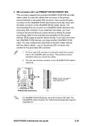
...orientation when you must configure the second drive as a slave device by setting its jumper accordingly. Secondary IDE Connector Primary IDE Connector P4S333 ® P4S333 IDE Connectors NOTE: Orient the red markings (usually zigzag) on the UltraDMA/100/66 cable is removed to the secondary IDE connector....devices with two ribbon cables - one for the primary IDE connector and another UltraDMA/100/66 cable. 2. BIOS supports specific device bootup. ASUS P4S333 motherboard user guide 2-23 PIN 1 For UltraDMA/100/66 IDE devices, use an 80-conductor IDE cable. Pin 20 on the UltraDMA ...
...orientation when you must configure the second drive as a slave device by setting its jumper accordingly. Secondary IDE Connector Primary IDE Connector P4S333 ® P4S333 IDE Connectors NOTE: Orient the red markings (usually zigzag) on the UltraDMA/100/66 cable is removed to the secondary IDE connector....devices with two ribbon cables - one for the primary IDE connector and another UltraDMA/100/66 cable. 2. BIOS supports specific device bootup. ASUS P4S333 motherboard user guide 2-23 PIN 1 For UltraDMA/100/66 IDE devices, use an 80-conductor IDE cable. Pin 20 on the UltraDMA ...

P4S333 English Manual
Page 47
... wiring and plug may damage the motherboard components. Lack of the expansion slots. PWRFAN1 GND +12V Rotation CPUFAN1 GND +12V Rotation P4S333 ® CHAFAN1 P4S333 12-Volt Fan Connectors Rotation +12V GND ASUS P4S333 motherboard user guide 2-25 CPU, Chassis, and Power Fan Connectors (3-pin CPUFAN1, CHASFAN1, PWRFAN1) The three fan connectors support cooling...
... wiring and plug may damage the motherboard components. Lack of the expansion slots. PWRFAN1 GND +12V Rotation CPUFAN1 GND +12V Rotation P4S333 ® CHAFAN1 P4S333 12-Volt Fan Connectors Rotation +12V GND ASUS P4S333 motherboard user guide 2-25 CPU, Chassis, and Power Fan Connectors (3-pin CPUFAN1, CHASFAN1, PWRFAN1) The three fan connectors support cooling...


