
Motherboard DIY Troubleshooting Guide
Page 1
® P4PE-X Motherboard
® P4PE-X Motherboard

P4PE-X User Manual
Page 1
Motherboard P4PE-X User Guide
Motherboard P4PE-X User Guide
P4PE-X User Manual
Page 3
Features Contents Notices v Safety information vi About this guide vii ASUS contact information viii P4PE-X specifications summary ix Chapter 1: Product introduction 1.1 Welcome 1-2 1.2 Package contents 1-2 1.3 Special features 1-3 1.4 Motherboard components 1-4 1.5 Motherboard layout 1-7 1.6 Before you proceed 1-8 1.7 Motherboard installation 1-9 1.7.1 Placement direction 1-9 1.7.2 Screw holes 1-9 1.8 Central Processing Unit (CPU 1-10 1.8.1 Overview 1-10 1.8.2 Installing the CPU 1-11 1.9 System memory 1-12 1.9.1 Memory configurations 1-12...
Features Contents Notices v Safety information vi About this guide vii ASUS contact information viii P4PE-X specifications summary ix Chapter 1: Product introduction 1.1 Welcome 1-2 1.2 Package contents 1-2 1.3 Special features 1-3 1.4 Motherboard components 1-4 1.5 Motherboard layout 1-7 1.6 Before you proceed 1-8 1.7 Motherboard installation 1-9 1.7.1 Placement direction 1-9 1.7.2 Screw holes 1-9 1.8 Central Processing Unit (CPU 1-10 1.8.1 Overview 1-10 1.8.2 Installing the CPU 1-11 1.9 System memory 1-12 1.9.1 Memory configurations 1-12...

P4PE-X User Manual
Page 6
Operation safety • Before installing the motherboard and adding devices on it may become wet. • Place the product on a stable surface. • If you detect any area where it , carefully read ... extremes. If you are not sure about the voltage of the electrical outlet you add a device. • Before connecting or removing signal cables from the motherboard, ensure that your area. If possible, disconnect all power cables are using an adpater or extension cord. These devices could interrupt the grounding circuit. •...
Operation safety • Before installing the motherboard and adding devices on it may become wet. • Place the product on a stable surface. • If you detect any area where it , carefully read ... extremes. If you are not sure about the voltage of the electrical outlet you add a device. • Before connecting or removing signal cables from the motherboard, ensure that your area. If possible, disconnect all power cables are using an adpater or extension cord. These devices could interrupt the grounding circuit. •...

P4PE-X User Manual
Page 11
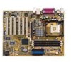
Product introduction Chapter 1 This chapter describes the features of the layout, jumper settings, and connectors. It includes brief descriptions of the motherboard components, and illustrations of the P4PE-X motherboard.
Product introduction Chapter 1 This chapter describes the features of the layout, jumper settings, and connectors. It includes brief descriptions of the motherboard components, and illustrations of the P4PE-X motherboard.

P4PE-X User Manual
Page 12
... check the items in your package with the list below. 1.2 Package contents Check your P4PE-X package for the following items. ASUS P4PE-X motherboard ATX form factor: 12 in x 9 in (30.5 cm x 22.9 cm) ASUS P4PE-X series support CD 80-conductor ribbon cables for UltraDMA/66/100/133 IDE drives Ribbon .../1600 DDR SDRAM, high-resolution graphics via an AGP 4X slot, USB 2.0, and 6-channel audio features, the P4PE-X is damaged or missing, contact your affordable vehicle to set a new benchmark for buying the ASUS® P4PE-X motherboard! Before you for a cost-effective desktop platform solution.
... check the items in your package with the list below. 1.2 Package contents Check your P4PE-X package for the following items. ASUS P4PE-X motherboard ATX form factor: 12 in x 9 in (30.5 cm x 22.9 cm) ASUS P4PE-X series support CD 80-conductor ribbon cables for UltraDMA/66/100/133 IDE drives Ribbon .../1600 DDR SDRAM, high-resolution graphics via an AGP 4X slot, USB 2.0, and 6-channel audio features, the P4PE-X is damaged or missing, contact your affordable vehicle to set a new benchmark for buying the ASUS® P4PE-X motherboard! Before you for a cost-effective desktop platform solution.

P4PE-X User Manual
Page 13
... memory support Employing the Double Data Rate (DDR) memory technology, the P4PE-X motherboard supports up to a fast 480 Mbps on the CPU FSB and DDR type. USB 2.0 technology The motherboard implements the new Universal Serial Bus (USB) 2.0 specification, extending the connection... the case to accommodate the Sony/Philips Digital Interface (S/PDIF) Out module. ASUS P4PE-X motherboard user guide 1-3 See page 1-12 for more information. 1.3 Special features Latest processor technology The P4PE-X motherboard supports the latest Intel® Pentium® 4 Processor via a 478-pin...
... memory support Employing the Double Data Rate (DDR) memory technology, the P4PE-X motherboard supports up to a fast 480 Mbps on the CPU FSB and DDR type. USB 2.0 technology The motherboard implements the new Universal Serial Bus (USB) 2.0 specification, extending the connection... the case to accommodate the Sony/Philips Digital Interface (S/PDIF) Out module. ASUS P4PE-X motherboard user guide 1-3 See page 1-12 for more information. 1.3 Special features Latest processor technology The P4PE-X motherboard supports the latest Intel® Pentium® 4 Processor via a 478-pin...

P4PE-X User Manual
Page 14
1.4 Motherboard components Before you install the motherboard, learn about its major components and available features to the succeeding pages for the component descriptions. 1 23 4 5 6 7 16 15 8 14 13 17 26 25 1-4 12 11 10 9 18 19 20 21 22 24 23 Chapter 1: Product introduction Refer to facilitate the installation and future upgrades.
1.4 Motherboard components Before you install the motherboard, learn about its major components and available features to the succeeding pages for the component descriptions. 1 23 4 5 6 7 16 15 8 14 13 17 26 25 1-4 12 11 10 9 18 19 20 21 22 24 23 Chapter 1: Product introduction Refer to facilitate the installation and future upgrades.
P4PE-X User Manual
Page 15
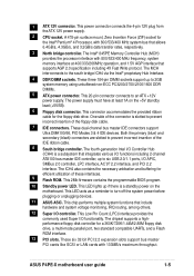
... support bus master PCI cards like SCSI or LAN cards with 800/533/400 MHz frequency, system memory interface at least 1A on the motherboard. One side of the connector is slotted to prevent incorrect insertion of the IDE ribbon cable. 8 South bridge controller. These dual-channel... of the floppy disk cable. 7 IDE connectors. This power connector connects the 4-pin 12V plug from the ATX 12V power supply. 2 CPU socket. ASUS P4PE-X motherboard user guide 1-5 A 478-pin surface mount, Zero Insertion Force (ZIF) socket for the floppy disk drive. This Low Pin Count (LPC) interface provides...
... support bus master PCI cards like SCSI or LAN cards with 800/533/400 MHz frequency, system memory interface at least 1A on the motherboard. One side of the connector is slotted to prevent incorrect insertion of the IDE ribbon cable. 8 South bridge controller. These dual-channel... of the floppy disk cable. 7 IDE connectors. This power connector connects the 4-pin 12V plug from the ATX 12V power supply. 2 CPU socket. ASUS P4PE-X motherboard user guide 1-5 A 478-pin surface mount, Zero Insertion Force (ZIF) socket for the floppy disk drive. This Low Pin Count (LPC) interface provides...

P4PE-X User Manual
Page 17
SEC_IDE PRI_IDE ATX Power Connector FLOPPY1 1.5 Motherboard layout PS/2KBMS T: Mouse B: Keyboard USB2.0 T: USB4 B: USB3 COM1 KBPWR1 22.86cm (9.0in) Socket 478 CPU_FAN1 CHA_FAN1 DDR DIMM1 (64/72 bit, 184-pin module) ... Memory Controller Hub (MCH) Accelerated Graphics Port (AGP) PCI1 P4PE-X PCI2 PCI3 PCI4 PCI5 PCI6 01 23 45 Intel I/O Controller Hub (ICH4) ® CR2032 3V Lithium Cell CMOS Power CLRTC ASUS ASIC with Hardware Monitor SB_PWR1 CHASSIS1 4Mbit Firmware Hub Super I/O IDE_LED1 FP_AUDIO1 USB_56 GAME1 PANEL1 30.5cm (12.0in) ASUS P4PE-X motherboard user guide 1-7
SEC_IDE PRI_IDE ATX Power Connector FLOPPY1 1.5 Motherboard layout PS/2KBMS T: Mouse B: Keyboard USB2.0 T: USB4 B: USB3 COM1 KBPWR1 22.86cm (9.0in) Socket 478 CPU_FAN1 CHA_FAN1 DDR DIMM1 (64/72 bit, 184-pin module) ... Memory Controller Hub (MCH) Accelerated Graphics Port (AGP) PCI1 P4PE-X PCI2 PCI3 PCI4 PCI5 PCI6 01 23 45 Intel I/O Controller Hub (ICH4) ® CR2032 3V Lithium Cell CMOS Power CLRTC ASUS ASIC with Hardware Monitor SB_PWR1 CHASSIS1 4Mbit Firmware Hub Super I/O IDE_LED1 FP_AUDIO1 USB_56 GAME1 PANEL1 30.5cm (12.0in) ASUS P4PE-X motherboard user guide 1-7

P4PE-X User Manual
Page 18
...component. 5. When lit, the standby LED (SB_PWR1) indicates that the system is detached from the wall socket before touching any motherboard component. ® P4PE-X P4PE-X Onboard LED SB_PWR1 ON Standby Power OFF Powered Off 1-8 Chapter 1: Product introduction Use a grounded wrist strap or touch a safely... 4. Unplug the power cord from the power supply. 1.6 Before you proceed Take note of the following precautions before you install motherboard components or change any component, place it on them due to static electricity. 3. Before you install or remove any component, ...
...component. 5. When lit, the standby LED (SB_PWR1) indicates that the system is detached from the wall socket before touching any motherboard component. ® P4PE-X P4PE-X Onboard LED SB_PWR1 ON Standby Power OFF Powered Off 1-8 Chapter 1: Product introduction Use a grounded wrist strap or touch a safely... 4. Unplug the power cord from the power supply. 1.6 Before you proceed Take note of the following precautions before you install motherboard components or change any component, place it on them due to static electricity. 3. Before you install or remove any component, ...

P4PE-X User Manual
Page 19
... the motherboard, study the configuration of the chassis ASUS P4PE-X motherboard user guide 1-9 Place this side towards the rear of your chassis to ensure that the motherboard fits into the holes indicated by circles to secure the motherboard to do so may damage the motherboard. 1.7 Motherboard installation ... part of the chassis as indicated in the correct orientation. Doing so may cause you physical injury and damage motherboard components. 1.7.1 Placement direction When installing the motherboard, make sure that measures 12 inches x 9 inches (30.5 cm x 22.9 cm). Failure to the ...
... the motherboard, study the configuration of the chassis ASUS P4PE-X motherboard user guide 1-9 Place this side towards the rear of your chassis to ensure that the motherboard fits into the holes indicated by circles to secure the motherboard to do so may damage the motherboard. 1.7 Motherboard installation ... part of the chassis as indicated in the correct orientation. Doing so may cause you physical injury and damage motherboard components. 1.7.1 Placement direction When installing the motherboard, make sure that measures 12 inches x 9 inches (30.5 cm x 22.9 cm). Failure to the ...
P4PE-X User Manual
Page 20
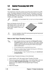
...Gold Mark Incorrect installation of 6.4GB/s, 4.2GB/s, and 3.2GB/s, respectively. Note in the 478-pin package with 512KB L2 cache on this motherboard: 1. Under Linux, use the Hyper-Threading Technology on 0.13 micron process. This processor supports 800*/533/400MHz front side bus (FSB), and...sure to enable the Hyper-Threading Technology item in BIOS to ensure system stability and performance. 2. 1.8 Central Processing Unit (CPU) 1.8.1 Overview The motherboard comes with 800MHz FSB, you need to use a PC3200 (400MHz) DDR module. If you installed a CPU with a surface mount 478-pin Zero...
...Gold Mark Incorrect installation of 6.4GB/s, 4.2GB/s, and 3.2GB/s, respectively. Note in the 478-pin package with 512KB L2 cache on this motherboard: 1. Under Linux, use the Hyper-Threading Technology on 0.13 micron process. This processor supports 800*/533/400MHz front side bus (FSB), and...sure to enable the Hyper-Threading Technology item in BIOS to ensure system stability and performance. 2. 1.8 Central Processing Unit (CPU) 1.8.1 Overview The motherboard comes with 800MHz FSB, you need to use a PC3200 (400MHz) DDR module. If you installed a CPU with a surface mount 478-pin Zero...
P4PE-X User Manual
Page 21
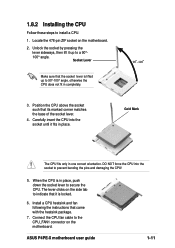
ASUS P4PE-X motherboard user guide 1-11 Unlock the socket by pressing the lever sideways, then lift it up to install a CPU. 1. DO NOT force the CPU into the socket until it is in place, push down the socket lever to the CPU_FAN1 connector on the motherboard. 2. The lever clicks on the side tab...is locked. 6. Carefully insert the CPU into the socket to a 90°- 100° angle. Locate the 478-pin ZIF socket on the motherboard. Connect the CPU fan cable to secure the CPU. Socket Lever Make sure that it fits in one correct orientation. Gold Mark The CPU fits...
ASUS P4PE-X motherboard user guide 1-11 Unlock the socket by pressing the lever sideways, then lift it up to install a CPU. 1. DO NOT force the CPU into the socket until it is in place, push down the socket lever to the CPU_FAN1 connector on the motherboard. 2. The lever clicks on the side tab...is locked. 6. Carefully insert the CPU into the socket to a 90°- 100° angle. Locate the 478-pin ZIF socket on the motherboard. Connect the CPU fan cable to secure the CPU. Socket Lever Make sure that it fits in one correct orientation. Gold Mark The CPU fits...

P4PE-X User Manual
Page 22
...empty. 2. You may install any DDR DIMMs with three Double Data Rate (DDR) Dual Inline Memory Module (DIMM) sockets. 1.9 System memory The motherboard comes with 64MB, 128MB, 256MB, 512MB, and 1GB densities into the DIMM sockets. These sockets support up . Use only the following combinations to ...install DDR DIMMs. Otherwise, the system may not boot up to install a CPU with 800MHz FSB. ® P4PE-X 80 Pins 104 Pins P4PE-X 184-Pin DDR DIMM Sockets 1.9.1 Memory configurations You may install single-sided DIMMs into DIMM2 socket, you need to 2GB system memory...
...empty. 2. You may install any DDR DIMMs with three Double Data Rate (DDR) Dual Inline Memory Module (DIMM) sockets. 1.9 System memory The motherboard comes with 64MB, 128MB, 256MB, 512MB, and 1GB densities into the DIMM sockets. These sockets support up . Use only the following combinations to ...install DDR DIMMs. Otherwise, the system may not boot up to install a CPU with 800MHz FSB. ® P4PE-X 80 Pins 104 Pins P4PE-X 184-Pin DDR DIMM Sockets 1.9.1 Memory configurations You may install single-sided DIMMs into DIMM2 socket, you need to 2GB system memory...

P4PE-X User Manual
Page 23
Visit the ASUS website (www.asus.com) for the latest qualified vendors list (QVL). 1.9.2 Installing a DIMM Make sure to both the motherboard and the components. Failure to do so may cause severe damage to unplug the power supply before adding or removing DIMMs or other system .... 3. Firmly insert the DIMM into the socket until the retaining clips snap back in place and the DIMM is properly seated. Unlocked Retaining Clip ASUS P4PE-X motherboard user guide 1-13 CPU FSB 800 MHz 533 MHz 400 MHz DDR DIMM Type PC3200 PC2700/PC2100 PC2100 Memory Frequency 400 MHz 333/266 MHz...
Visit the ASUS website (www.asus.com) for the latest qualified vendors list (QVL). 1.9.2 Installing a DIMM Make sure to both the motherboard and the components. Failure to do so may cause severe damage to unplug the power supply before adding or removing DIMMs or other system .... 3. Firmly insert the DIMM into the socket until the retaining clips snap back in place and the DIMM is properly seated. Unlocked Retaining Clip ASUS P4PE-X motherboard user guide 1-13 CPU FSB 800 MHz 533 MHz 400 MHz DDR DIMM Type PC3200 PC2700/PC2100 PC2100 Memory Frequency 400 MHz 333/266 MHz...
P4PE-X User Manual
Page 24
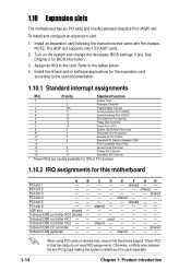
.... 2. PCI slot 5 -- shared - - - - - - - - - -- - - - - -- - AGP slot shared - shared - - - - - - shared - - - - - - - - - - To install and configure an expansion card: 1. See Chapter 2 for this motherboard AB PCI slot 1 -- PCI slot 4 -- shared - - - - - - shared - - used - - - - 1.10 Expansion slots The motherboard has six PCI slots and one Accelerated Graphics Port (AGP) slot. C D E F GH - - - shared - - Otherwise, conflicts arise between the two...
.... 2. PCI slot 5 -- shared - - - - - - - - - -- - - - - -- - AGP slot shared - shared - - - - - - shared - - - - - - - - - - To install and configure an expansion card: 1. See Chapter 2 for this motherboard AB PCI slot 1 -- PCI slot 4 -- shared - - - - - - shared - - used - - - - 1.10 Expansion slots The motherboard has six PCI slots and one Accelerated Graphics Port (AGP) slot. C D E F GH - - - shared - - Otherwise, conflicts arise between the two...

P4PE-X User Manual
Page 25
...in the BIOS (see section 2.5.1 Power Up Control). Removing the cap will cause system boot failure! ® P4PE-X CLRTC 12 23 P4PE-X Clear RTC RAM Disable (Default) Enable You do not need to clear the RTC when the system hangs ... parameter settings to wake up feature. For system failure due to re-enter data. KBPWR1 12 23 P4PE-X +5V +5VSB ® (Default) P4PE-X Keyboard Power Setting 2. Except when clearing the RTC RAM, never remove the cap on the +5VSB...CLRTC1 jumper default position. Plug the power cord and turn ON the computer. 4. ASUS P4PE-X motherboard user guide 1-15
...in the BIOS (see section 2.5.1 Power Up Control). Removing the cap will cause system boot failure! ® P4PE-X CLRTC 12 23 P4PE-X Clear RTC RAM Disable (Default) Enable You do not need to clear the RTC when the system hangs ... parameter settings to wake up feature. For system failure due to re-enter data. KBPWR1 12 23 P4PE-X +5V +5VSB ® (Default) P4PE-X Keyboard Power Setting 2. Except when clearing the RTC RAM, never remove the cap on the +5VSB...CLRTC1 jumper default position. Plug the power cord and turn ON the computer. 4. ASUS P4PE-X motherboard user guide 1-15

P4PE-X User Manual
Page 26
... Alarm Lead (Default) 1-16 Chapter 1: Product introduction 1.12 Connectors This section describes and illustrates the internal connectors on the motherboard. 1. P4PE-X IDE_LED1 P4PE-X HD Activity LED 2. TIP: If the case-mounted LED does not ® light up . Hard disk activity LED (2-pin IDE_LED1) This connector supplies power to ...
... Alarm Lead (Default) 1-16 Chapter 1: Product introduction 1.12 Connectors This section describes and illustrates the internal connectors on the motherboard. 1. P4PE-X IDE_LED1 P4PE-X HD Activity LED 2. TIP: If the case-mounted LED does not ® light up . Hard disk activity LED (2-pin IDE_LED1) This connector supplies power to ...
P4PE-X User Manual
Page 27
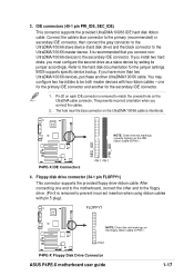
...secondary IDE connector. 1. After connecting one for the jumper settings. FLOPPY1 ® P4PE-X NOTE: Orient the red markings on the IDE ribbon cable to PIN 1. 3. PIN 1 P4PE-X Floppy Disk Drive Connector ASUS P4PE-X motherboard user guide 1-17 If you install two hard disks, you connect the cables.... drive connector (34-1 pin FLOPPY1) This connector supports the provided floppy drive ribbon cable. SEC_IDE PRI_IDE P4PE-X IDE Connectors PIN 1 PIN 1 4. one end to the motherboard, connect the other end to the floppy drive. (Pin 5 is removed to prevent incorrect insertion when...
...secondary IDE connector. 1. After connecting one for the jumper settings. FLOPPY1 ® P4PE-X NOTE: Orient the red markings on the IDE ribbon cable to PIN 1. 3. PIN 1 P4PE-X Floppy Disk Drive Connector ASUS P4PE-X motherboard user guide 1-17 If you install two hard disks, you connect the cables.... drive connector (34-1 pin FLOPPY1) This connector supports the provided floppy drive ribbon cable. SEC_IDE PRI_IDE P4PE-X IDE Connectors PIN 1 PIN 1 4. one end to the motherboard, connect the other end to the floppy drive. (Pin 5 is removed to prevent incorrect insertion when...


