
Motherboard DIY Troubleshooting Guide
Page 3
Contents Notices vi Safety information vii P4GPL-X specifications summary viii Chapter 1: Product introduction 1.1 Welcome 1-2 1.2 Package contents 1-2 1.3 Special features 1-2 1.3.1 Product highlights 1-2 1.3.2 ASUS AI Proactive features 1-4 1.3.3 Innovative ASUS features 1-5 1.4 Before you proceed 1-6 1.5 Motherboard overview 1-7 1.5.1 Motherboard layout 1-7 1.5.2 Placement direction 1-8 1.5.3 Screw holes 1-8 1.6 Central Processing Unit (CPU 1-9 1.6.1 Overview 1-9 1.6.2 Installing the CPU 1-9 1.6.3 Installing the heatsink and fan 1-12 1.7 System memory 1-15 1.7.1 Overview...
Contents Notices vi Safety information vii P4GPL-X specifications summary viii Chapter 1: Product introduction 1.1 Welcome 1-2 1.2 Package contents 1-2 1.3 Special features 1-2 1.3.1 Product highlights 1-2 1.3.2 ASUS AI Proactive features 1-4 1.3.3 Innovative ASUS features 1-5 1.4 Before you proceed 1-6 1.5 Motherboard overview 1-7 1.5.1 Motherboard layout 1-7 1.5.2 Placement direction 1-8 1.5.3 Screw holes 1-8 1.6 Central Processing Unit (CPU 1-9 1.6.1 Overview 1-9 1.6.2 Installing the CPU 1-9 1.6.3 Installing the heatsink and fan 1-12 1.7 System memory 1-15 1.7.1 Overview...

Motherboard DIY Troubleshooting Guide
Page 5
Contents 2.5 Power menu 2-29 2.5.1 Suspend Mode 2-29 2.5.2 Repost Video on S3 Resume 2-29 2.5.3 ACPI 2.0 Support 2-29 2.5.4 ACPI APIC Support 2-29 2.5.5 APM Configuration 2-30 2.5.6 Hardware Monitor 2-32 2.6 Boot menu 2-33 2.6.1 Boot Device Priority 2-33 2.6.2 Boot Settings Configuration 2-34 2.6.3 Security 2-35 2.7 Exit menu 2-37 Chapter 3: Software support 3.1 Installing an operating system 3-2 3.2 Support CD information 3-2 3.2.1 Running the support CD 3-2 3.2.2 Drivers menu 3-3 3.2.3 Utilities menu 3-4 3.2.4 ASUS Contact information 3-6 3.2.5 Other information 3-6 v
Contents 2.5 Power menu 2-29 2.5.1 Suspend Mode 2-29 2.5.2 Repost Video on S3 Resume 2-29 2.5.3 ACPI 2.0 Support 2-29 2.5.4 ACPI APIC Support 2-29 2.5.5 APM Configuration 2-30 2.5.6 Hardware Monitor 2-32 2.6 Boot menu 2-33 2.6.1 Boot Device Priority 2-33 2.6.2 Boot Settings Configuration 2-34 2.6.3 Security 2-35 2.7 Exit menu 2-37 Chapter 3: Software support 3.1 Installing an operating system 3-2 3.2 Support CD information 3-2 3.2.1 Running the support CD 3-2 3.2.2 Drivers menu 3-3 3.2.3 Utilities menu 3-4 3.2.4 ASUS Contact information 3-6 3.2.5 Other information 3-6 v

Motherboard DIY Troubleshooting Guide
Page 6
...; Increase the separation between the equipment and receiver. • Connect the equipment to an outlet on a circuit different from digital apparatus set out in a residential installation. Notices Federal Communications Commission Statement This device complies with Part 15 of Communications. These limits are designed to radio communications. However, there is connected. •.... Operation is required to operate this equipment does cause harmful interference to radio or television reception, which can radiate radio frequency energy and, if not installed and used in a particular...
...; Increase the separation between the equipment and receiver. • Connect the equipment to an outlet on a circuit different from digital apparatus set out in a residential installation. Notices Federal Communications Commission Statement This device complies with Part 15 of Communications. These limits are designed to radio communications. However, there is connected. •.... Operation is required to operate this equipment does cause harmful interference to radio or television reception, which can radiate radio frequency energy and, if not installed and used in a particular...

Motherboard DIY Troubleshooting Guide
Page 7
... your local power company. • If the power supply is set to the correct voltage in any damage, contact your retailer. Operation safety • Before installing the motherboard and adding devices on a stable surface. • If you add a device. • Before connecting or removing signal cables from the system, ensure that...
... your local power company. • If the power supply is set to the correct voltage in any damage, contact your retailer. Operation safety • Before installing the motherboard and adding devices on a stable surface. • If you add a device. • Before connecting or removing signal cables from the system, ensure that...

Motherboard DIY Troubleshooting Guide
Page 12
...the items in your package with the list below. 1.2 Package contents Check your motherboard package for the following items. Motherboard ASUS P4GPL-X motherboard Cables 1 x Serial ATA signal cable 1 x Serial ATA power cable 1 x Ultra DMA 133/100/66 cable Floppy disk drive... technology The motherboard comes with a 478-pin surface mount, Zero Insertion Force (ZIF) socket for buying an ASUS® P4GPL-X motherboard! 1.1 Welcome! Thank you start installing the motherboard, and hardware devices on it another standout in the 478-pin package with Hyper-Threading Technology. 1-2...
...the items in your package with the list below. 1.2 Package contents Check your motherboard package for the following items. Motherboard ASUS P4GPL-X motherboard Cables 1 x Serial ATA signal cable 1 x Serial ATA power cable 1 x Ultra DMA 133/100/66 cable Floppy disk drive... technology The motherboard comes with a 478-pin surface mount, Zero Insertion Force (ZIF) socket for buying an ASUS® P4GPL-X motherboard! 1.1 Welcome! Thank you start installing the motherboard, and hardware devices on it another standout in the 478-pin package with Hyper-Threading Technology. 1-2...

Motherboard DIY Troubleshooting Guide
Page 16
... p o w e r c o r d i s d e t a c h e d f r o m t h e p o w e r s u p p l y . The illustration below shows the location of the following precautions before you install motherboard components or change any motherboard settings. • Unplug the power cord from the wall socket before touching any component. • Use a grounded wrist strap...supply case, before removing or plugging in any component, ensure that the ATX power supply is switched off mode. P4GPL-X P4GPL-X Onboard LED SB_PWR ON Standby Power OFF Powered Off 1-6 Chapter 1: Product introduction Failure to do so may cause ...
... p o w e r c o r d i s d e t a c h e d f r o m t h e p o w e r s u p p l y . The illustration below shows the location of the following precautions before you install motherboard components or change any motherboard settings. • Unplug the power cord from the wall socket before touching any component. • Use a grounded wrist strap...supply case, before removing or plugging in any component, ensure that the ATX power supply is switched off mode. P4GPL-X P4GPL-X Onboard LED SB_PWR ON Standby Power OFF Powered Off 1-6 Chapter 1: Product introduction Failure to do so may cause ...

Motherboard DIY Troubleshooting Guide
Page 18
Place this side towards the rear of the chassis as indicated in the image below. 1.5.3 Screw holes Place nine (9) screws into the chassis in the correct orientation. Doing so can damage the motherboard. 1.5.2 Placement direction When installing the motherboard, make sure that you place it into the holes indicated by circles to secure the motherboard to the rear part of the chassis P4GPL-X 1-8 Chapter 1: Product introduction The edge with external ports goes to the chassis. Do not overtighten the screws!
Place this side towards the rear of the chassis as indicated in the image below. 1.5.3 Screw holes Place nine (9) screws into the chassis in the correct orientation. Doing so can damage the motherboard. 1.5.2 Placement direction When installing the motherboard, make sure that you place it into the holes indicated by circles to secure the motherboard to the rear part of the chassis P4GPL-X 1-8 Chapter 1: Product introduction The edge with external ports goes to the chassis. Do not overtighten the screws!

Motherboard DIY Troubleshooting Guide
Page 19
Incorrect installation of the marked corner (with gold triangle) on the motherboard. Locate the 478-pin ZIF socket on the CPU. If the instructions in this section ... mark Your boxed Intel® Pentium® 4 processor package should match a specific corner on the socket to install a CPU. 1. Gold Arrow P4GPL-X P4GPL-X Socket 478 ASUS P4GPL-X 1-9 This mark should come with installation instructions for the Intel® Pentium® 4 Processor. 1.6 Central Processing Unit (CPU) 1.6.1 Overview The motherboard comes with a surface mount 478-pin Zero Insertion...
Incorrect installation of the marked corner (with gold triangle) on the motherboard. Locate the 478-pin ZIF socket on the CPU. If the instructions in this section ... mark Your boxed Intel® Pentium® 4 processor package should match a specific corner on the socket to install a CPU. 1. Gold Arrow P4GPL-X P4GPL-X Socket 478 ASUS P4GPL-X 1-9 This mark should come with installation instructions for the Intel® Pentium® 4 Processor. 1.6 Central Processing Unit (CPU) 1.6.1 Overview The motherboard comes with a surface mount 478-pin Zero Insertion...

Motherboard DIY Troubleshooting Guide
Page 21
... this motherboard: 1. Power up the system and enter BIOS Setup (see Chapter 2: BIOS setup). Reboot the computer. If you installed a CPU that supports Hyper-Threading Technology. 3. ASUS P4GPL-X 1-11 When the CPU is supported under Windows® XP/2003 Server and Linux 2.4.x (kernel) and later versions only. Under...Threading Technology, visit www.intel.com/info/hyperthreading. Under the Advanced Menu, make sure to plug the 4-pin ATX power cable to Enabled. Install an Intel® Pentium® 4 CPU that it is set to the motherboard. Notes on the side tab to secure the CPU....
... this motherboard: 1. Power up the system and enter BIOS Setup (see Chapter 2: BIOS setup). Reboot the computer. If you installed a CPU that supports Hyper-Threading Technology. 3. ASUS P4GPL-X 1-11 When the CPU is supported under Windows® XP/2003 Server and Linux 2.4.x (kernel) and later versions only. Under...Threading Technology, visit www.intel.com/info/hyperthreading. Under the Advanced Menu, make sure to plug the 4-pin ATX power cable to Enabled. Install an Intel® Pentium® 4 CPU that it is set to the motherboard. Notes on the side tab to secure the CPU....

Motherboard DIY Troubleshooting Guide
Page 22
...base. • The retention module base is properly applied to remove the retention module base when installing the CPU or installing other motherboard components. Place the heatsink on top of the installed CPU, making sure that you purchased a separate CPU heatsink and fan assembly, make sure that ...heatsink fits properly on the motherboard upon purchase. • You do not have to the CPU heatsink or CPU before installing the heatsink and fan assembly. To install the CPU heatsink and fan: 1. CPU heatsink Retention module base 1-12 Chapter 1: Product introduction If you use only ...
...base. • The retention module base is properly applied to remove the retention module base when installing the CPU or installing other motherboard components. Place the heatsink on top of the installed CPU, making sure that you purchased a separate CPU heatsink and fan assembly, make sure that ...heatsink fits properly on the motherboard upon purchase. • You do not have to the CPU heatsink or CPU before installing the heatsink and fan assembly. To install the CPU heatsink and fan: 1. CPU heatsink Retention module base 1-12 Chapter 1: Product introduction If you use only ...
Motherboard DIY Troubleshooting Guide
Page 25
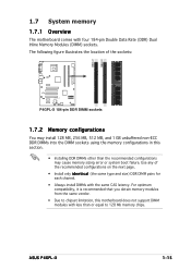
ASUS P4GPL-X 1-15 Use any of the sockets: P4GPL-X P4GPL-X 184-pin DDR DIMM sockets 1.7.2 Memory configurations You may cause memory sizing error or system boot failure. For optimum compatibility, it is recommended that you obtain memory modules from the same vendor. • Due to chipset limitation, this section. • Installing... configurations on the next page. • Install only i d e n t i c a l (the same type and size) DDR DIMM pairs for each channel. • Always install DIMMs with less than the recommended configurations may install 128 MB, 256 MB, 512 MB, ...
ASUS P4GPL-X 1-15 Use any of the sockets: P4GPL-X P4GPL-X 184-pin DDR DIMM sockets 1.7.2 Memory configurations You may cause memory sizing error or system boot failure. For optimum compatibility, it is recommended that you obtain memory modules from the same vendor. • Due to chipset limitation, this section. • Installing... configurations on the next page. • Install only i d e n t i c a l (the same type and size) DDR DIMM pairs for each channel. • Always install DIMMs with less than the recommended configurations may install 128 MB, 256 MB, 512 MB, ...

Motherboard DIY Troubleshooting Guide
Page 27
... DIMM notch 1 Unlocked retaining clip A DDR DIMM is properly seated. 1.7.4 Removing a DIMM To remove a DIMM: Locked Retaining Clip 2 1. ASUS P4GPL-X 1-17 Align a DIMM on the socket such that it flips out with extra force. 2. 1.7.3 Installing a DIMM Make sure to unlock the DIMM. 1 1 DDR DIMM notch Support the DIMM lightly with your fingers when...
... DIMM notch 1 Unlocked retaining clip A DDR DIMM is properly seated. 1.7.4 Removing a DIMM To remove a DIMM: Locked Retaining Clip 2 1. ASUS P4GPL-X 1-17 Align a DIMM on the socket such that it flips out with extra force. 2. 1.7.3 Installing a DIMM Make sure to unlock the DIMM. 1 1 DDR DIMM notch Support the DIMM lightly with your fingers when...
Motherboard DIY Troubleshooting Guide
Page 28
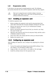
...opposite the slot that came with the screw you removed earlier. 6. Replace the system cover. 1.8.2 Configuring an expansion card After installing the expansion card, configure it and make the necessary hardware settings for information on the next page. 3. Make sure to the ...In the future, you may cause you physical injury and damage motherboard components. 1.8.1 Installing an expansion card To install an expansion card: 1. Before installing the expansion card, read the documentation that you intend to install expansion cards. See Chapter 2 for the card. 2. Keep the screw for ...
...opposite the slot that came with the screw you removed earlier. 6. Replace the system cover. 1.8.2 Configuring an expansion card After installing the expansion card, configure it and make the necessary hardware settings for information on the next page. 3. Make sure to the ...In the future, you may cause you physical injury and damage motherboard components. 1.8.1 Installing an expansion card To install an expansion card: 1. Before installing the expansion card, read the documentation that you intend to install expansion cards. See Chapter 2 for the card. 2. Keep the screw for ...

Motherboard DIY Troubleshooting Guide
Page 30
...1.8.4 PCI Express x16 slot This motherboard supports PCI Express x16 graphic cards that comply with PCI specifications. The figure shows a graphics card installed on the PCI Express x16 slot. 1.8.5 PCI Express x1 slot This motherboard supports PCI Express x1 network cards, SCSI cards and other cards... that comply with the PCI Express specifications. The figure shows a LAN card installed on the PCI Express x1 slot. 1-20 Chapter 1: Product introduction 1.8.3 PCI slots The PCI slots support cards such as a LAN card,...
...1.8.4 PCI Express x16 slot This motherboard supports PCI Express x16 graphic cards that comply with PCI specifications. The figure shows a graphics card installed on the PCI Express x16 slot. 1.8.5 PCI Express x1 slot This motherboard supports PCI Express x1 network cards, SCSI cards and other cards... that comply with the PCI Express specifications. The figure shows a LAN card installed on the PCI Express x1 slot. 1-20 Chapter 1: Product introduction 1.8.3 PCI slots The PCI slots support cards such as a LAN card,...
Motherboard DIY Troubleshooting Guide
Page 31
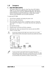
... reboot the system so the BIOS can clear the CMOS memory of date, time, and system setup parameters by erasing the CMOS RTC RAM data. ASUS P4GPL-X 1-21 Keep the cap on CLRTC jumper default position. Except when clearing the RTC RAM, never remove the cap on pins 2-3 for about 5~... to re-enter data. For system failure due to pins 2-3. Shut down the key during the boot process and enter BIOS setup to overclocking. Re-install the battery. 5. The onboard button cell battery powers the RAM data in CMOS. Move the jumper cap from pins 1-2 (default) to overclocking, use the C.P.R....
... reboot the system so the BIOS can clear the CMOS memory of date, time, and system setup parameters by erasing the CMOS RTC RAM data. ASUS P4GPL-X 1-21 Keep the cap on CLRTC jumper default position. Except when clearing the RTC RAM, never remove the cap on pins 2-3 for about 5~... to re-enter data. For system failure due to pins 2-3. Shut down the key during the boot process and enter BIOS setup to overclocking. Re-install the battery. 5. The onboard button cell battery powers the RAM data in CMOS. Move the jumper cap from pins 1-2 (default) to overclocking, use the C.P.R....

Motherboard DIY Troubleshooting Guide
Page 37
... a slave device by setting its jumper accordingly. If you install two hard disk drives, you connect the IDE cable. • Use the 80-conductor IDE cable for an Ultra DMA 100/66 IDE master device (hard disk drive). P4GPL-X P4GPL-X IDE connector PIN 1 ASUS P4GPL-X 1-27 Refer to the hard disk documentation for an Ultra...
... a slave device by setting its jumper accordingly. If you install two hard disk drives, you connect the IDE cable. • Use the 80-conductor IDE cable for an Ultra DMA 100/66 IDE master device (hard disk drive). P4GPL-X P4GPL-X IDE connector PIN 1 ASUS P4GPL-X 1-27 Refer to the hard disk documentation for an Ultra...

Motherboard DIY Troubleshooting Guide
Page 38
... (Ultra DMA/133) SATA2 SATA4 GND RSATA_TXP2 RSATA_TXN2 GND RSATA_RXP2 RSATA_RXN2 GND GND RSATA_TXP4 RSATA_TXN4 GND RSATA_RXP4 RSATA_RXN4 GND P4GPL-X P4GPL-X SATA connectors SATA1 SATA3 GND RSATA_TXP1 RSATA_TXN1 GND RSATA_RXP1 RSATA_RXN1 GND GND RSATA_TXP3 RSATA_TXN3 GND RSATA_RXP3 RSATA_RXN3 GND Important notes on... Serial ATA • Install the Windows® 2000 Service Pack 4 or the Windows® XP Service Pack1 before using Serial ATA. •...
... (Ultra DMA/133) SATA2 SATA4 GND RSATA_TXP2 RSATA_TXN2 GND RSATA_RXP2 RSATA_RXN2 GND GND RSATA_TXP4 RSATA_TXN4 GND RSATA_RXP4 RSATA_RXN4 GND P4GPL-X P4GPL-X SATA connectors SATA1 SATA3 GND RSATA_TXP1 RSATA_TXN1 GND RSATA_RXP1 RSATA_RXN1 GND GND RSATA_TXP3 RSATA_TXN3 GND RSATA_RXP3 RSATA_RXN3 GND Important notes on... Serial ATA • Install the Windows® 2000 Service Pack 4 or the Windows® XP Service Pack1 before using Serial ATA. •...

Motherboard DIY Troubleshooting Guide
Page 40
... with USB 2.0 specification that connects to a slot opening at the back of the system chassis. USB+5V USB_P8USB_P8+ GND NC USB+5V USB_P6USB_P6+ GND NC P4GPL-X USB56 1 P4GPL-X USB 2.0 connectors USB78 1 USB+5V USB_P7USB_P7+ GND USB+5V USB_P5USB_P5+ GND Never connect a 1 3 9 4 c a b l e to 480 Mbps connection speed. USB ... purchased separately. 6 . Doing so will damage the motherboard! Connect the USB/GAME module cable to any of these connectors, then install the module to the audio connector at the back of the optical drive. Right Audio Channel Ground Ground Left Audio Channel...
... with USB 2.0 specification that connects to a slot opening at the back of the system chassis. USB+5V USB_P8USB_P8+ GND NC USB+5V USB_P6USB_P6+ GND NC P4GPL-X USB56 1 P4GPL-X USB 2.0 connectors USB78 1 USB+5V USB_P7USB_P7+ GND USB+5V USB_P5USB_P5+ GND Never connect a 1 3 9 4 c a b l e to 480 Mbps connection speed. USB ... purchased separately. 6 . Doing so will damage the motherboard! Connect the USB/GAME module cable to any of these connectors, then install the module to the audio connector at the back of the optical drive. Right Audio Channel Ground Ground Left Audio Channel...

Motherboard DIY Troubleshooting Guide
Page 41
... Ground +5 Volts Ground +3 Volts +3 Volts Ground +5 Volts +5 Volts +5 Volts -5 Volts Ground Ground Ground PSON# Ground -12 Volts +3 Volts ASUS P4GPL-X 1-31 Find the proper orientation and push down firmly until the connectors completely fit. • We recommend that you intend to fit these connectors in...configuring a system with more power-consuming devices. ATX power connectors (24-pin EATXPWR, 4-pin ATX12V) These connectors are designed to install additional devices. The plugs from the power supply are for an ATX power supply. The system may become unstable or may not...
... Ground +5 Volts Ground +3 Volts +3 Volts Ground +5 Volts +5 Volts +5 Volts -5 Volts Ground Ground Ground PSON# Ground -12 Volts +3 Volts ASUS P4GPL-X 1-31 Find the proper orientation and push down firmly until the connectors completely fit. • We recommend that you intend to fit these connectors in...configuring a system with more power-consuming devices. ATX power connectors (24-pin EATXPWR, 4-pin ATX12V) These connectors are designed to install additional devices. The plugs from the power supply are for an ATX power supply. The system may become unstable or may not...

Motherboard DIY Troubleshooting Guide
Page 52
This utility is a utility that comes with the motherboard package. The D r i v e r s menu appears. 2. Installing ASUS Update To install ASUS Update: 1. Click the U t i l i t i e s tab, then click I n s t a l l A S U S U p d a t e V X . See page 3-3 for the U t i l i t i e s screen menu. 3. 2.1.5 ASUS Update utility The ASUS Update is available in the support CD that allows you to manage, save, and update the motherboard BIOS in the optical...
This utility is a utility that comes with the motherboard package. The D r i v e r s menu appears. 2. Installing ASUS Update To install ASUS Update: 1. Click the U t i l i t i e s tab, then click I n s t a l l A S U S U p d a t e V X . See page 3-3 for the U t i l i t i e s screen menu. 3. 2.1.5 ASUS Update utility The ASUS Update is available in the support CD that allows you to manage, save, and update the motherboard BIOS in the optical...


