
Motherboard DIY Troubleshooting Guide
Page 12
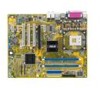
... 1.3.1 Product highlights Latest processor technology The motherboard comes with a 478-pin surface mount, Zero Insertion Force (ZIF) socket for buying an ASUS® P4GPL-X motherboard! The motherboard also supports Intel® Pentium® 4 processors with 1 MB/512 KB/256 KB L2 cache. Before you ...processor in the long line of the above items is damaged or missing, contact your motherboard package for the following items. Motherboard ASUS P4GPL-X motherboard Cables 1 x Serial ATA signal cable 1 x Serial ATA power cable 1 x Ultra DMA 133/100/66 cable Floppy disk drive ...
... 1.3.1 Product highlights Latest processor technology The motherboard comes with a 478-pin surface mount, Zero Insertion Force (ZIF) socket for buying an ASUS® P4GPL-X motherboard! The motherboard also supports Intel® Pentium® 4 processors with 1 MB/512 KB/256 KB L2 cache. Before you ...processor in the long line of the above items is damaged or missing, contact your motherboard package for the following items. Motherboard ASUS P4GPL-X motherboard Cables 1 x Serial ATA signal cable 1 x Serial ATA power cable 1 x Ultra DMA 133/100/66 cable Floppy disk drive ...
Motherboard DIY Troubleshooting Guide
Page 13
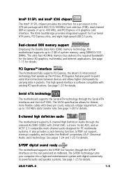
... rate. The S/PDIF technology turns your computer into a high-end entertainment system with digital connectivity to 400 MHz, and PCI Express x16 graphics card interface. ASUS P4GPL-X 1-3 Dual-channel DDR memory support Employing the Double Data Rate (DDR) memory technology, the motherboard supports up to powerful audio and speaker systems. See page...
... rate. The S/PDIF technology turns your computer into a high-end entertainment system with digital connectivity to 400 MHz, and PCI Express x16 graphics card interface. ASUS P4GPL-X 1-3 Dual-channel DDR memory support Employing the Double Data Rate (DDR) memory technology, the motherboard supports up to powerful audio and speaker systems. See page...

Motherboard DIY Troubleshooting Guide
Page 15
...allows you can easily update the system BIOS even before loading the operating system. ASUS EZ Flash BIOS With the ASUS EZ Flash, you to restore the original BIOS data from a floppy disk. ASUS MyLogo2™ This feature allows you to personalize and add style to open the... allows automatic re-setting to the BIOS default settings in case when the BIOS codes and data are corrupted. C.P.R. (CPU Parameter Recall) The C.P.R. ASUS P4GPL-X 1-5 No need to overclocking. This protection eliminates the need to overclocking, C.P.R. See page 2-34 for details. When the system hangs due to...
...allows you can easily update the system BIOS even before loading the operating system. ASUS EZ Flash BIOS With the ASUS EZ Flash, you to restore the original BIOS data from a floppy disk. ASUS MyLogo2™ This feature allows you to personalize and add style to open the... allows automatic re-setting to the BIOS default settings in case when the BIOS codes and data are corrupted. C.P.R. (CPU Parameter Recall) The C.P.R. ASUS P4GPL-X 1-5 No need to overclocking. This protection eliminates the need to overclocking, C.P.R. See page 2-34 for details. When the system hangs due to...
Motherboard DIY Troubleshooting Guide
Page 17
... Center:Line Out Below:Mic In Marvell 88E8053 USBPW12 USBPW34 ATX12V CPU_FAN Intel® 915PL PCIEX1_1 PCIEX16 PCI1 CD PCI2 R Intel ICH6 ALC880 AAFP PCI3 P4GPL-X PCIEX1_2 PCIEX1_3 SB_PWR CR2032 3V Lithium Cell CMOS Power USB56 USBPW78 USBPW56 Intel FWH 4Mb USB78 PRI_IDE EATXPWR SATA2 SATA4 SATA1 SATA3 CLRTC PANEL CHA_FAN...
... Center:Line Out Below:Mic In Marvell 88E8053 USBPW12 USBPW34 ATX12V CPU_FAN Intel® 915PL PCIEX1_1 PCIEX16 PCI1 CD PCI2 R Intel ICH6 ALC880 AAFP PCI3 P4GPL-X PCIEX1_2 PCIEX1_3 SB_PWR CR2032 3V Lithium Cell CMOS Power USB56 USBPW78 USBPW56 Intel FWH 4Mb USB78 PRI_IDE EATXPWR SATA2 SATA4 SATA1 SATA3 CLRTC PANEL CHA_FAN...

Motherboard DIY Troubleshooting Guide
Page 19
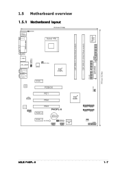
... the socket to install a CPU. 1. 1.6 Central Processing Unit (CPU) 1.6.1 Overview The motherboard comes with installation instructions for the Intel® Pentium® 4 Processor. Gold Arrow P4GPL-X P4GPL-X Socket 478 ASUS P4GPL-X 1-9 If the instructions in this section do not match the CPU documentation, follow the latter.
... the socket to install a CPU. 1. 1.6 Central Processing Unit (CPU) 1.6.1 Overview The motherboard comes with installation instructions for the Intel® Pentium® 4 Processor. Gold Arrow P4GPL-X P4GPL-X Socket 478 ASUS P4GPL-X 1-9 If the instructions in this section do not match the CPU documentation, follow the latter.

Motherboard DIY Troubleshooting Guide
Page 21
... BIOS Setup (see Chapter 2: BIOS setup). Install an Intel® Pentium® 4 CPU that the item H y p e r - After installation, make sure that supports Hyper-Threading Technology. 2. ASUS P4GPL-X 1-11
... BIOS Setup (see Chapter 2: BIOS setup). Install an Intel® Pentium® 4 CPU that the item H y p e r - After installation, make sure that supports Hyper-Threading Technology. 2. ASUS P4GPL-X 1-11

Motherboard DIY Troubleshooting Guide
Page 23
Position the fan with the retention mechanism on each corner of the module base. Align and snap the four hooks of the heatsink. ASUS P4GPL-X 1-13 Retention lock Retention hole Retention hook snapped to the retention hole Keep the retention locks lifted upward while fitting the retention mechanism to the holes on top of the retention mechanism to the module base. Make sure that the fan and retention mechanism assembly perfectly fits the heatsink and module base; 2. otherwise, you cannot snap the hooks into the holes.
Position the fan with the retention mechanism on each corner of the module base. Align and snap the four hooks of the heatsink. ASUS P4GPL-X 1-13 Retention lock Retention hole Retention hook snapped to the retention hole Keep the retention locks lifted upward while fitting the retention mechanism to the holes on top of the retention mechanism to the module base. Make sure that the fan and retention mechanism assembly perfectly fits the heatsink and module base; 2. otherwise, you cannot snap the hooks into the holes.
Motherboard DIY Troubleshooting Guide
Page 25
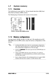
..., this section. • Installing DDR DIMMs other than or equal to 128 Mb memory chips. Use any of the sockets: P4GPL-X P4GPL-X 184-pin DDR DIMM sockets 1.7.2 Memory configurations You may cause memory sizing error or system boot failure. DIMM_A1 DIMM_B1 1.7 System memory... 1.7.1 Overview The motherboard comes with four 184-pin Double Data Rate (DDR) Dual Inline Memory Modules (DIMM) sockets. ASUS P4GPL-X 1-15 The following figure illustrates the location of the recommended configurations on the next page. • Install only i d e n t i c a...
..., this section. • Installing DDR DIMMs other than or equal to 128 Mb memory chips. Use any of the sockets: P4GPL-X P4GPL-X 184-pin DDR DIMM sockets 1.7.2 Memory configurations You may cause memory sizing error or system boot failure. DIMM_A1 DIMM_B1 1.7 System memory... 1.7.1 Overview The motherboard comes with four 184-pin Double Data Rate (DDR) Dual Inline Memory Modules (DIMM) sockets. ASUS P4GPL-X 1-15 The following figure illustrates the location of the recommended configurations on the next page. • Install only i d e n t i c a...

Motherboard DIY Troubleshooting Guide
Page 27
.... Firmly insert the DIMM into a socket to unlock the DIMM. 1 1 DDR DIMM notch Support the DIMM lightly with your fingers when pressing the retaining clips. ASUS P4GPL-X 1-17 1.7.3 Installing a DIMM Make sure to both the motherboard and the components. 1.
.... Firmly insert the DIMM into a socket to unlock the DIMM. 1 1 DDR DIMM notch Support the DIMM lightly with your fingers when pressing the retaining clips. ASUS P4GPL-X 1-17 1.7.3 Installing a DIMM Make sure to both the motherboard and the components. 1.
Motherboard DIY Troubleshooting Guide
Page 29
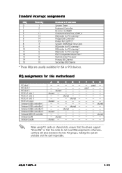
... will arise between the two PCI groups, making the system unstable and the card inoperable. IRQ assignments for ISA or PCI devices. shared - - - shared - - -- -- - -- - shared - - -- F - ASUS P4GPL-X 1-19 shared - - -- -- - -- -- - shared - - -- - -
... will arise between the two PCI groups, making the system unstable and the card inoperable. IRQ assignments for ISA or PCI devices. shared - - - shared - - -- -- - -- - shared - - -- F - ASUS P4GPL-X 1-19 shared - - -- -- - -- -- - shared - - -- - -
Motherboard DIY Troubleshooting Guide
Page 31
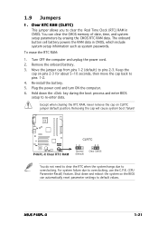
... the cap on pins 2-3 for about 5~10 seconds, then move the cap back to pins 2-3. You can automatically reset parameter settings to re-enter data. P4GPL-X P4GPL-X Clear RTC RAM CLRTC 12 23 Normal (Default) Clear CMOS You do not need to clear the RTC when the system hangs due to overclocking... from pins 1-2 (default) to pins 1-2. 4. The onboard button cell battery powers the RAM data in CMOS. Plug the power cord and turn ON the computer. 6. ASUS P4GPL-X 1-21
... the cap on pins 2-3 for about 5~10 seconds, then move the cap back to pins 2-3. You can automatically reset parameter settings to re-enter data. P4GPL-X P4GPL-X Clear RTC RAM CLRTC 12 23 Normal (Default) Clear CMOS You do not need to clear the RTC when the system hangs due to overclocking... from pins 1-2 (default) to pins 1-2. 4. The onboard button cell battery powers the RAM data in CMOS. Plug the power cord and turn ON the computer. 6. ASUS P4GPL-X 1-21
Motherboard DIY Troubleshooting Guide
Page 33
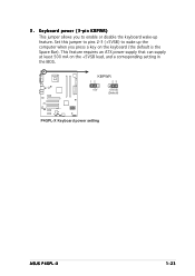
Keyboard power (3-pin KBPWR) This jumper allows you to wake up feature. Set this jumper to pins 2-3 (+5VSB) to enable or disable the keyboard wake-up the computer when you press a key on the +5VSB lead, and a corresponding setting in the BIOS. KBPWR 12 23 +5V +5VSB (Default) P4GPL-X P4GPL-X Keyboard power setting ASUS P4GPL-X 1-23 This feature requires an ATX power supply that can supply at least 500 mA on the keyboard (the default is the Space Bar). 3.
Keyboard power (3-pin KBPWR) This jumper allows you to wake up feature. Set this jumper to pins 2-3 (+5VSB) to enable or disable the keyboard wake-up the computer when you press a key on the +5VSB lead, and a corresponding setting in the BIOS. KBPWR 12 23 +5V +5VSB (Default) P4GPL-X P4GPL-X Keyboard power setting ASUS P4GPL-X 1-23 This feature requires an ATX power supply that can supply at least 500 mA on the keyboard (the default is the Space Bar). 3.
Motherboard DIY Troubleshooting Guide
Page 35
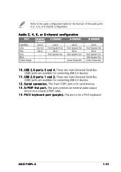
... Speaker Out Side Speaker Out Center/Subwoofer 1 0 . This port connects an external audio output device via a coaxial S/PDIF cable. 1 4 . This port is for a PS/2 keyboard. ASUS P4GPL-X 1-25 U S B 2 . 0 p o r t s 1 a n d 2 . S / P D I F O u t p o r t . U S B 2 . 0 p o r t s 3 a n d 4 . These two 4-pin Universal Serial Bus (USB) ports are available for connecting USB 2.0 devices. 1 2 . Audio 2, 4, 6, or 8-channel configuration Port Light Blue Lime Pink Gray...
... Speaker Out Side Speaker Out Center/Subwoofer 1 0 . This port connects an external audio output device via a coaxial S/PDIF cable. 1 4 . This port is for a PS/2 keyboard. ASUS P4GPL-X 1-25 U S B 2 . 0 p o r t s 1 a n d 2 . S / P D I F O u t p o r t . U S B 2 . 0 p o r t s 3 a n d 4 . These two 4-pin Universal Serial Bus (USB) ports are available for connecting USB 2.0 devices. 1 2 . Audio 2, 4, 6, or 8-channel configuration Port Light Blue Lime Pink Gray...

Motherboard DIY Troubleshooting Guide
Page 37
... DMA 100/66 IDE devices. This prevents incorrect insertion when you must configure the second drive as a slave device by setting its jumper accordingly. P4GPL-X P4GPL-X IDE connector PIN 1 ASUS P4GPL-X 1-27 If you install two hard disk drives, you connect the IDE cable. • Use the 80-conductor IDE cable for an Ultra...
... DMA 100/66 IDE devices. This prevents incorrect insertion when you must configure the second drive as a slave device by setting its jumper accordingly. P4GPL-X P4GPL-X IDE connector PIN 1 ASUS P4GPL-X 1-27 If you install two hard disk drives, you connect the IDE cable. • Use the 80-conductor IDE cable for an Ultra...

Motherboard DIY Troubleshooting Guide
Page 39
... 1A~2.22A (26.64W max.) at +12V. Insufficient air flow inside the system may damage the motherboard components. CPU_FAN Rotation +12V GND P4GPL-X P4GPL-X Fan connectors CHA_FAN GND +12V Rotation ASUS P4GPL-X 1-29 Do not forget to connect the fan cables to the fan connectors on the fan connectors. 4. Connect the fan cables to...
... 1A~2.22A (26.64W max.) at +12V. Insufficient air flow inside the system may damage the motherboard components. CPU_FAN Rotation +12V GND P4GPL-X P4GPL-X Fan connectors CHA_FAN GND +12V Rotation ASUS P4GPL-X 1-29 Do not forget to connect the fan cables to the fan connectors on the fan connectors. 4. Connect the fan cables to...

Motherboard DIY Troubleshooting Guide
Page 41
... Volts +5V Standby Power OK Ground +5 Volts Ground +5 Volts Ground +3 Volts +3 Volts Ground +5 Volts +5 Volts +5 Volts -5 Volts Ground Ground Ground PSON# Ground -12 Volts +3 Volts ASUS P4GPL-X 1-31 Find the proper orientation and push down firmly until the connectors completely fit. • We recommend that the PSU has a minimum power rating of...
... Volts +5V Standby Power OK Ground +5 Volts Ground +5 Volts Ground +3 Volts +3 Volts Ground +5 Volts +5 Volts +5 Volts -5 Volts Ground Ground Ground PSON# Ground -12 Volts +3 Volts ASUS P4GPL-X 1-31 Find the proper orientation and push down firmly until the connectors completely fit. • We recommend that the PSU has a minimum power rating of...
Motherboard DIY Troubleshooting Guide
Page 43
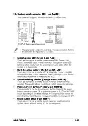
...• Hard disk drive activity (Red 2-pin IDE_LED) This 2-pin connector is for the system power button. PWR Ground Reset Ground P4GPL-X IDE LED P4GPL-X System panel connector Reset PWR SW The sytem panel connector is for easy connection. Refer to the connector description below for details. &#...hear system beeps and warnings. • Power/Soft-off the system power. PLED SPEAKER PLED+ PLED+5V Ground Ground Speaker PANEL IDE_LED+ IDE_LED- ASUS P4GPL-X 1-33 13. The IDE LED lights up when you to the HDD. • System warning speaker (Orange 4-pin SPEAKER) This 4-pin ...
...• Hard disk drive activity (Red 2-pin IDE_LED) This 2-pin connector is for the system power button. PWR Ground Reset Ground P4GPL-X IDE LED P4GPL-X System panel connector Reset PWR SW The sytem panel connector is for easy connection. Refer to the connector description below for details. &#...hear system beeps and warnings. • Power/Soft-off the system power. PLED SPEAKER PLED+ PLED+5V Ground Ground Speaker PANEL IDE_LED+ IDE_LED- ASUS P4GPL-X 1-33 13. The IDE LED lights up when you to the HDD. • System warning speaker (Orange 4-pin SPEAKER) This 4-pin ...

Motherboard DIY Troubleshooting Guide
Page 47
... • Do not shut down or reset the system while updating the BIOS to P4GPL-X.ROM. Copy the original or the latest motherboard BIOS file to the bootable floppy disk. 2.1.2 ASUS EZ Flash utility The ASUS EZ Flash feature allows you rename the BIOS file to prevent system boot failure! ...• A "Floppy not found ! X . R O M. 2. A "P4GPL-X.ROM not found , EZ Flash performs the BIOS update process and ...
... • Do not shut down or reset the system while updating the BIOS to P4GPL-X.ROM. Copy the original or the latest motherboard BIOS file to the bootable floppy disk. 2.1.2 ASUS EZ Flash utility The ASUS EZ Flash feature allows you rename the BIOS file to prevent system boot failure! ...• A "Floppy not found ! X . R O M. 2. A "P4GPL-X.ROM not found , EZ Flash performs the BIOS update process and ...

Motherboard DIY Troubleshooting Guide
Page 49
...(C) 2002 American Megatrends, Inc. A:\>afudos /iP4GPL-X.ROM AMI Firmware Update Utility - Version 1.10 Copyright (C) 2002 American Megatrends, Inc. done A:\> ASUS P4GPL-X 2-5 Save the BIOS file to type the exact BIOS filename at the prompt type: afudos /i[filename] where [filename] is completed. You need... latest or the original BIOS file on a piece of paper. done Writing flash .... 0x0008CC00 (9%) Verifying flash .. Visit the ASUS website (www.asus.com) and download the latest BIOS file for the motherboard. Reading file ..... Reboot the system from the motherboard support CD to...
...(C) 2002 American Megatrends, Inc. A:\>afudos /iP4GPL-X.ROM AMI Firmware Update Utility - Version 1.10 Copyright (C) 2002 American Megatrends, Inc. done A:\> ASUS P4GPL-X 2-5 Save the BIOS file to type the exact BIOS filename at the prompt type: afudos /i[filename] where [filename] is completed. You need... latest or the original BIOS file on a piece of paper. done Writing flash .... 0x0008CC00 (9%) Verifying flash .. Visit the ASUS website (www.asus.com) and download the latest BIOS file for the motherboard. Reading file ..... Reboot the system from the motherboard support CD to...
Motherboard DIY Troubleshooting Guide
Page 51
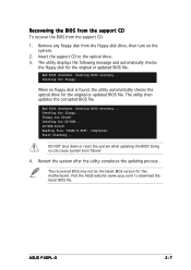
... support CD To recover the BIOS from the floppy disk drive, then turn on the system. 2. Starting BIOS recovery... Visit the ASUS website (www.asus.com) to the optical drive. 3. Floppy not found , the utility automatically checks the optical drive for floppy... Restart the system ... to download the latest BIOS file. Reading file "P4GPL-X.ROM". DO NOT shut down or reset the system while updating the BIOS! The utility displays the following message and automatically checks the floppy disk for this motherboard. ASUS P4GPL-X 2-7 Checking for the original or updated BIOS file...
... support CD To recover the BIOS from the floppy disk drive, then turn on the system. 2. Starting BIOS recovery... Visit the ASUS website (www.asus.com) to the optical drive. 3. Floppy not found , the utility automatically checks the optical drive for floppy... Restart the system ... to download the latest BIOS file. Reading file "P4GPL-X.ROM". DO NOT shut down or reset the system while updating the BIOS! The utility displays the following message and automatically checks the floppy disk for this motherboard. ASUS P4GPL-X 2-7 Checking for the original or updated BIOS file...


