
P4GE-V User Manual
Page 11
P4GE-V specifications summary CPU Chipset Front Side Bus (FSB) Memory Expansion slots VGA IDE Audio LAN Special features Rear panel I/O Socket 478 for Intel® Pentium&#...; mode ASUS POST Reporter™ ASUS EZ Plug™ ASUS Q-Fan ASUS EZ Flash C.P.R. (CPU Parameter Recall) CrashFree BIOS Power Loss Restart SFS (Stepless Frequency Selection) CPU throttle Adjustable CPU VCORE, memory, and AGP voltages Multi-language BIOS AGP warning LED 1 x Parallel port 1 x Serial port 1 x Video port 1 x PS/2 keyboard port 1 x PS/2 mouse port 4 x USB 2.0/USB 1.1 ports...
P4GE-V specifications summary CPU Chipset Front Side Bus (FSB) Memory Expansion slots VGA IDE Audio LAN Special features Rear panel I/O Socket 478 for Intel® Pentium&#...; mode ASUS POST Reporter™ ASUS EZ Plug™ ASUS Q-Fan ASUS EZ Flash C.P.R. (CPU Parameter Recall) CrashFree BIOS Power Loss Restart SFS (Stepless Frequency Selection) CPU throttle Adjustable CPU VCORE, memory, and AGP voltages Multi-language BIOS AGP warning LED 1 x Parallel port 1 x Serial port 1 x Video port 1 x PS/2 keyboard port 1 x PS/2 mouse port 4 x USB 2.0/USB 1.1 ports...

P4GE-V User Manual
Page 12
P4GE-V specifications summary Internal I/O BIOS features Industry standard Manageability Form Factor Support CD contents 1 x USB 2.0/1.1 connector for 2 additional USB ports CPU/Power/Chassis fan connectors 20-pin/4-pin ATX 12V power connectors IDE LED/Power LED connectors Chassis ... audio connectors Front panel audio connector 4Mb Flash ROM, Award BIOS, TCAV, PnP, DMI2.0, WfM2.0, SM BIOS2.3, Multi-language BIOS, ASUS EZ Flash, CrashFree BIOS, C.P.R. (CPU Parameter Recall) PCI 2.2, USB 2.0 WfM 2.0. DMI 2.0, WOL/WOR by PME, chassis intrusion, SMBus ATX form factor: 12 in x 9.0 in (30.5 cm...
P4GE-V specifications summary Internal I/O BIOS features Industry standard Manageability Form Factor Support CD contents 1 x USB 2.0/1.1 connector for 2 additional USB ports CPU/Power/Chassis fan connectors 20-pin/4-pin ATX 12V power connectors IDE LED/Power LED connectors Chassis ... audio connectors Front panel audio connector 4Mb Flash ROM, Award BIOS, TCAV, PnP, DMI2.0, WfM2.0, SM BIOS2.3, Multi-language BIOS, ASUS EZ Flash, CrashFree BIOS, C.P.R. (CPU Parameter Recall) PCI 2.2, USB 2.0 WfM 2.0. DMI 2.0, WOL/WOR by PME, chassis intrusion, SMBus ATX form factor: 12 in x 9.0 in (30.5 cm...
P4GE-V User Manual
Page 15
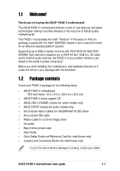
... platform solution. Thank you start installing the motherboard, and hardware devices on it another standout in (30.5 cm x 22.9 cm) ASUS P4GE-V series support CD ASUS USB 2.0/GAME module (for audio models only) ASUS S/PDIF module (for audio models only) 80-conductor ribbon cables for UltraDMA/66/100 IDE drives 40-conductor IDE cable Ribbon...
... platform solution. Thank you start installing the motherboard, and hardware devices on it another standout in (30.5 cm x 22.9 cm) ASUS P4GE-V series support CD ASUS USB 2.0/GAME module (for audio models only) ASUS S/PDIF module (for audio models only) 80-conductor ribbon cables for UltraDMA/66/100 IDE drives 40-conductor IDE cable Ribbon...

P4GE-V User Manual
Page 16
... frequencies for the latest 3D graphics, multimedia, and Internet applications. USB 2.0 technology The motherboard implements the new Universal Serial Bus (USB) 2.0 specification, extending the connection speed from 12 Mbps on USB 2.0. DDR memory support Employing the Double Data Rate (DDR) memory technology, the P4GE-V motherboard supports up to accommodate the bundled Sony/Philips Digital...
... frequencies for the latest 3D graphics, multimedia, and Internet applications. USB 2.0 technology The motherboard implements the new Universal Serial Bus (USB) 2.0 specification, extending the connection speed from 12 Mbps on USB 2.0. DDR memory support Employing the Double Data Rate (DDR) memory technology, the P4GE-V motherboard supports up to accommodate the bundled Sony/Philips Digital...

P4GE-V User Manual
Page 20
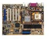
... you avoid mistakes that may damage the board and its physical configuration and available features to Chapter 2 for the specifications of the P4GE-V motherboard as pointed out in the picture on the components. 1-6 Chapter 1: Product introduction South Bridge controller 10. Standby power LED...DDR DIMM sockets 5. IDE connectors 9. Speech controller 11. PS/2 mouse port 21. Parallel port 22. Microphone jack 26. USB 2.0 ports 1 and 2 30. ATX power connector 7. ASUS ASIC 14. Audio CODEC 17. RJ-45 port (optional) 23. Line In jack 24. Keyboard port See page 1-8...
... you avoid mistakes that may damage the board and its physical configuration and available features to Chapter 2 for the specifications of the P4GE-V motherboard as pointed out in the picture on the components. 1-6 Chapter 1: Product introduction South Bridge controller 10. Standby power LED...DDR DIMM sockets 5. IDE connectors 9. Speech controller 11. PS/2 mouse port 21. Parallel port 22. Microphone jack 26. USB 2.0 ports 1 and 2 30. ATX power connector 7. ASUS ASIC 14. Audio CODEC 17. RJ-45 port (optional) 23. Line In jack 24. Keyboard port See page 1-8...

P4GE-V User Manual
Page 22
...the processor interface with 533/400 MHz system bus that integrates various I/O functions including 2-channel ATA/100 bus master IDE controller, up to six USB 2.0/1.1 ports, I /O Controller Hub (ICH4) is used if you don't have at least 1A on the +5V standby lead (+5VSB)....the primary (blue) and secondary (black) connectors are slotted to prevent incorrect insertion of the IDE ribbon cable. 9 South bridge controller. This ASUS patented auxilliary power connector is a subsystem that allows 4.3GB/s and 3.2GB/s data transfer rates, respectively. 3 North bridge controller. The ICH4 also...
...the processor interface with 533/400 MHz system bus that integrates various I/O functions including 2-channel ATA/100 bus master IDE controller, up to six USB 2.0/1.1 ports, I /O Controller Hub (ICH4) is used if you don't have at least 1A on the +5V standby lead (+5VSB)....the primary (blue) and secondary (black) connectors are slotted to prevent incorrect insertion of the IDE ribbon cable. 9 South bridge controller. This ASUS patented auxilliary power connector is a subsystem that allows 4.3GB/s and 3.2GB/s data transfer rates, respectively. 3 North bridge controller. The ICH4 also...

P4GE-V User Manual
Page 24
This Line In (light blue) jack connects a tape player or other serial devices. 29 USB 2.0 ports 1 and 2. In 6-channel mode, the function of this jack becomes Rear Speaker Out. 26 USB 2.0 ports 3 and 4. This Mic (pink) jack connects a microphone. In 6channel mode, the function of this jack becomes Bass/Center. ... Out jack. In 6-channel mode, the function of this jack becomes Front Speaker Out. 25 Microphone jack. These two 4-pin Universal Serial Bus (USB) ports are available for a VGA monitor or other VGA-compatible devices. 28 Serial port. This 9-pin COM1 port is for connecting...
This Line In (light blue) jack connects a tape player or other serial devices. 29 USB 2.0 ports 1 and 2. In 6-channel mode, the function of this jack becomes Rear Speaker Out. 26 USB 2.0 ports 3 and 4. This Mic (pink) jack connects a microphone. In 6channel mode, the function of this jack becomes Bass/Center. ... Out jack. In 6-channel mode, the function of this jack becomes Front Speaker Out. 25 Microphone jack. These two 4-pin Universal Serial Bus (USB) ports are available for a VGA monitor or other VGA-compatible devices. 28 Serial port. This 9-pin COM1 port is for connecting...

P4GE-V User Manual
Page 40
...are usually available for this motherboard AB PCI slot 1 -- Onboard USB controller HC0 shared - Onboard LAN controller -- PCI slot 4 -- PCI slot 5 -- Onboard USB controller HC1 - - shared - - used - - - -... need IRQ assignments. Otherwise, conflicts will arise between the two PCI groups, making the system unstable and the card inoperable. 2-14 Chapter 2: Hardware information Onboard USB 2.0 controller - - C D E F GH - - - IRQ assignments for ISA or PCI devices. PCI slot 2 -- PCI slot 3 -- AGP slot shared - shared - - - - - - ...
...are usually available for this motherboard AB PCI slot 1 -- Onboard USB controller HC0 shared - Onboard LAN controller -- PCI slot 4 -- PCI slot 5 -- Onboard USB controller HC1 - - shared - - used - - - -... need IRQ assignments. Otherwise, conflicts will arise between the two PCI groups, making the system unstable and the card inoperable. 2-14 Chapter 2: Hardware information Onboard USB 2.0 controller - - C D E F GH - - - IRQ assignments for ISA or PCI devices. PCI slot 2 -- PCI slot 3 -- AGP slot shared - shared - - - - - - ...

P4GE-V User Manual
Page 41
... AGP cards. The following figure shows a LAN card installed on this motherboard, including an ASUS proprietary BlueMagic PCI slot. As long as this motherboard! ® P4GE-V P4GE-V Accelerated Graphics Port (AGP) ASUS P4GE-V motherboard user guide 2-15 When you buy an AGP card, make sure that you installed... an incorrect AGP card, such as a LAN card, SCSI card, USB card, and other 3.3V AGP card, the ...
... AGP cards. The following figure shows a LAN card installed on this motherboard, including an ASUS proprietary BlueMagic PCI slot. As long as this motherboard! ® P4GE-V P4GE-V Accelerated Graphics Port (AGP) ASUS P4GE-V motherboard user guide 2-15 When you buy an AGP card, make sure that you installed... an incorrect AGP card, such as a LAN card, SCSI card, USB card, and other 3.3V AGP card, the ...

P4GE-V User Manual
Page 42
... power supply that can supply at least 1A on the keyboard (the default is the Space Bar). KBPWR1 12 23 P4GE-V +5V +5VSB ® (Default) P4GE-V Keyboard Power Setting 2. Wireless PCI and USB settings (3-pin WPCI_USB) These jumpers are reserved. 2.7 Jumpers 1. Keyboard power (3-pin KBPWR1) This jumper allows you press a key on the...
... power supply that can supply at least 1A on the keyboard (the default is the Space Bar). KBPWR1 12 23 P4GE-V +5V +5VSB ® (Default) P4GE-V Keyboard Power Setting 2. Wireless PCI and USB settings (3-pin WPCI_USB) These jumpers are reserved. 2.7 Jumpers 1. Keyboard power (3-pin KBPWR1) This jumper allows you press a key on the...
P4GE-V User Manual
Page 49
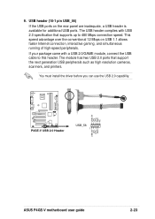
... faster Internet connection, interactive gaming, and simultaneous running of high-speed peripherals. The USB header complies with a USB 2.0/GAME module, connect the USB cable to 480 Mbps connection speed. USB+5V LP5LP5+ GND NC ® P4GE-V P4GE-V USB 2.0 Header USB_56 1 USB+5V LP4LP4+ GND ASUS P4GE-V motherboard user guide 2-23 You must install the driver before you can use the...
... faster Internet connection, interactive gaming, and simultaneous running of high-speed peripherals. The USB header complies with a USB 2.0/GAME module, connect the USB cable to 480 Mbps connection speed. USB+5V LP5LP5+ GND NC ® P4GE-V P4GE-V USB 2.0 Header USB_56 1 USB+5V LP4LP4+ GND ASUS P4GE-V motherboard user guide 2-23 You must install the driver before you can use the...

P4GE-V User Manual
Page 50
10. The MODEM connector allows the onboard audio to interface with a voice modem card with the optional USB 2.0/GAME module, connect the GAME/MIDI cable to receive stereo audio input from sound sources such as a speaker) between the audio and a voice modem... GND GND J1CX J1B1 +5V GAME1 1 MIDI_IN J2B2 J2CY MIDI_OUT J2CX J2B1 +5V P4GE-V Game Connector 11. MODEM1 Modem-In Ground Ground Modem-Out ® P4GE-V CD1(Black) AUX1 (White) Left Audio Channel Ground Ground Right Audio Channel P4GE-V Internal Audio Connectors 2-24 Chapter 2: Hardware information GAME/MIDI connector (16-1 pin...
10. The MODEM connector allows the onboard audio to interface with a voice modem card with the optional USB 2.0/GAME module, connect the GAME/MIDI cable to receive stereo audio input from sound sources such as a speaker) between the audio and a voice modem... GND GND J1CX J1B1 +5V GAME1 1 MIDI_IN J2B2 J2CY MIDI_OUT J2CX J2B1 +5V P4GE-V Game Connector 11. MODEM1 Modem-In Ground Ground Modem-Out ® P4GE-V CD1(Black) AUX1 (White) Left Audio Channel Ground Ground Right Audio Channel P4GE-V Internal Audio Connectors 2-24 Chapter 2: Hardware information GAME/MIDI connector (16-1 pin...

P4GE-V User Manual
Page 82
... OS/2 Onboard Memory > 64M [Disabled] When using OS/2 operating systems with installed DRAM of [Auto] allows the system to [Disabled], the USB controller legacy mode is [By SPD], which configures items 2-5 by reading the contents in the SPD (Serial Presence Detect) device. The EEPROM on... the memory modules that you are using a USB device. Configuration options: [Disabled] [Enabled] 4.4.1 Chip Configuration SDRAM Configuration [By SPD] This parameter allows you set the optimal timings for ...
... OS/2 Onboard Memory > 64M [Disabled] When using OS/2 operating systems with installed DRAM of [Auto] allows the system to [Disabled], the USB controller legacy mode is [By SPD], which configures items 2-5 by reading the contents in the SPD (Serial Presence Detect) device. The EEPROM on... the memory modules that you are using a USB device. Configuration options: [Disabled] [Enabled] 4.4.1 Chip Configuration SDRAM Configuration [By SPD] This parameter allows you set the optimal timings for ...

P4GE-V User Manual
Page 85
...supports the AGP 4X interface that are using onboard VGA. Configuration options: [Both] [Primary] [Secondary] [Disabled] USB 2.0 HS Reference Voltage [Medium] This item controls the USB 2.0 high-speed drive strength reference voltage. Memory Hole At 15M-16M [Disabled] This field allows you may not boot... to UC (uncacheable) if your display card does not support this to 16MB. Configuration options: [Low] [Medium] [High] [Maximum] ASUS P4GE-V motherboard user guide 4-23 It can greatly improve the display speed by caching the display data. AGP 4X is a new cache technology for...
...supports the AGP 4X interface that are using onboard VGA. Configuration options: [Both] [Primary] [Secondary] [Disabled] USB 2.0 HS Reference Voltage [Medium] This item controls the USB 2.0 high-speed drive strength reference voltage. Memory Hole At 15M-16M [Disabled] This field allows you may not boot... to UC (uncacheable) if your display card does not support this to 16MB. Configuration options: [Low] [Medium] [High] [Maximum] ASUS P4GE-V motherboard user guide 4-23 It can greatly improve the display speed by caching the display data. AGP 4X is a new cache technology for...

P4GE-V User Manual
Page 88
... Palette Snoop [Disabled] Some non-standard VGA cards, like graphics accelerators or MPEG video cards, may not show colors properly. USB 1.1 Controllers [3 Controllers] This field allows you to select the number of USB 1.1 controllers that you are using standard VGA cards, leave this field to activate. Configuration options: [Disabled] [3 Controllers] 4-26 Chapter...
... Palette Snoop [Disabled] Some non-standard VGA cards, like graphics accelerators or MPEG video cards, may not show colors properly. USB 1.1 Controllers [3 Controllers] This field allows you to select the number of USB 1.1 controllers that you are using standard VGA cards, leave this field to activate. Configuration options: [Disabled] [3 Controllers] 4-26 Chapter...

P4GE-V User Manual
Page 89
... VGA] The option [Onboard VGA] appears only when the onboard VGA is either used or enabled. Configuration options: [Disabled] [Enabled] ASUS P4GE-V motherboard user guide 4-27 Configuration options: [Disabled] [Enabled] Primary VGA BIOS [PCI VGA Card] This field allows you to enable or... disable the onboard USB 2.0 controller. Configuration options: [Disabled] [Enabled] Onboard LAN Boot ROM [Disabled] This field allows you to install USB 2.0 devices. Set to [Enabled] if you wish to select the primary graphics card....
... VGA] The option [Onboard VGA] appears only when the onboard VGA is either used or enabled. Configuration options: [Disabled] [Enabled] ASUS P4GE-V motherboard user guide 4-27 Configuration options: [Disabled] [Enabled] Primary VGA BIOS [PCI VGA Card] This field allows you to enable or... disable the onboard USB 2.0 controller. Configuration options: [Disabled] [Enabled] Onboard LAN Boot ROM [Disabled] This field allows you to install USB 2.0 devices. Set to [Enabled] if you wish to select the primary graphics card....

P4GE-V User Manual
Page 129
... 1-3, 1-8, 2-23 ASUS iPanel 2-31 ATX power 1-6, 2-27 chassis intrusion 2-22 fan 2-24 floppy disk 1-6, 2-18 front panel audio 2-28 game/MIDI 2-26 IDE 1-9, 2-19 IDE LED 2-18 infrared 2-27 internal audio 2-26 panel 2-29 power supply thermal 2-24 S/PDIF 2-28 SMBus 2-22 USB header 2-25 D ...DDR SDRAM technology 2-10 Digital audio interface 1-3 DIMM installing 2-12 removing 2-12 DIMM sockets 1-10 Double Data Rate (DDR) memory 1-2 ASUS P4GE-V motherboard user guide I-1
... 1-3, 1-8, 2-23 ASUS iPanel 2-31 ATX power 1-6, 2-27 chassis intrusion 2-22 fan 2-24 floppy disk 1-6, 2-18 front panel audio 2-28 game/MIDI 2-26 IDE 1-9, 2-19 IDE LED 2-18 infrared 2-27 internal audio 2-26 panel 2-29 power supply thermal 2-24 S/PDIF 2-28 SMBus 2-22 USB header 2-25 D ...DDR SDRAM technology 2-10 Digital audio interface 1-3 DIMM installing 2-12 removing 2-12 DIMM sockets 1-10 Double Data Rate (DDR) memory 1-2 ASUS P4GE-V motherboard user guide I-1

P4GE-V User Manual
Page 130
... 4-12 Sectors 4-14 Types 4-12 Hardware Monitor 4-33 Heatsink installation 2-7 I IRQ assignments 2-14 J JumperFree mode 2-16 Jumpers Clear RTC 2-17 keyboard power 2-16 wireless PCI / USB 2-16 K Keyboard Auto-Repeat Delay 4-16 Auto-Repeat Rate 4-16 L LEDs AGP warning 1-10, 2-3 standby power 1-10, 2-3 Legacy Diskette 4-10 M Motherboard major components 1-6 IRQ Table...
... 4-12 Sectors 4-14 Types 4-12 Hardware Monitor 4-33 Heatsink installation 2-7 I IRQ assignments 2-14 J JumperFree mode 2-16 Jumpers Clear RTC 2-17 keyboard power 2-16 wireless PCI / USB 2-16 K Keyboard Auto-Repeat Delay 4-16 Auto-Repeat Rate 4-16 L LEDs AGP warning 1-10, 2-3 standby power 1-10, 2-3 Legacy Diskette 4-10 M Motherboard major components 1-6 IRQ Table...
P4GE-V User Manual
Page 131
... CAS Delay 4-21 Serial Ports 1-10, 4-24 SMART Monitoring 4-15 Sony/Philips Digital Interface (S/PDIF) 1-3, 2-28 Super I/O controller 1-9 Support CD 5-1 ASUS Update 5-9 Utilities menu 5-5 Drivers menu 5-2 motherboard information 5-7 multi-channel audio 5-21 Technical Support Form 5-8 Suspend Mode 4-29 System Controller North Bridge 1-8 South... Bridge 1-9 System Date 4-10 System memory configurations 2-11 System Time 4-10 U UART2 4-24 Ultra DMA Mode 4-15 USB Legacy Support 4-20 USB ports 1-10 V Video memory cache USWC 4-22 UC 4-22 Z ZIF socket 2-5 ASUS P4GE-V motherboard user guide I-3
... CAS Delay 4-21 Serial Ports 1-10, 4-24 SMART Monitoring 4-15 Sony/Philips Digital Interface (S/PDIF) 1-3, 2-28 Super I/O controller 1-9 Support CD 5-1 ASUS Update 5-9 Utilities menu 5-5 Drivers menu 5-2 motherboard information 5-7 multi-channel audio 5-21 Technical Support Form 5-8 Suspend Mode 4-29 System Controller North Bridge 1-8 South... Bridge 1-9 System Date 4-10 System memory configurations 2-11 System Time 4-10 U UART2 4-24 Ultra DMA Mode 4-15 USB Legacy Support 4-20 USB ports 1-10 V Video memory cache USWC 4-22 UC 4-22 Z ZIF socket 2-5 ASUS P4GE-V motherboard user guide I-3


