
Motherboard DIY Troubleshooting Guide
Page 3
... guide vii Conventions used in this guide vii Typography vii P4GE-MX specifications summary viii Chapter 1: Product introduction 1.1 Welcome 1-2 1.2 Package contents 1-2 1.3 Special features 1-3 1.3.1 Product Highlights 1-3 1.3.2 Unique ASUS features 1-4 1.4 Before you proceed 1-5 1.5 Motherboard overview 1-6 1.5.1 Motherboard layout 1-6 1.5.2 Placement direction 1-7 1.5.3 Screw holes 1-7 1.6 Central Processing Unit (CPU 1-8 1.6.1 Overview 1-8 1.6.2 Installing the CPU 1-9 1.7 System memory 1-10 1.7.1 DIMM sockets location 1-10...
... guide vii Conventions used in this guide vii Typography vii P4GE-MX specifications summary viii Chapter 1: Product introduction 1.1 Welcome 1-2 1.2 Package contents 1-2 1.3 Special features 1-3 1.3.1 Product Highlights 1-3 1.3.2 Unique ASUS features 1-4 1.4 Before you proceed 1-5 1.5 Motherboard overview 1-6 1.5.1 Motherboard layout 1-6 1.5.2 Placement direction 1-7 1.5.3 Screw holes 1-7 1.6 Central Processing Unit (CPU 1-8 1.6.1 Overview 1-8 1.6.2 Installing the CPU 1-9 1.7 System memory 1-10 1.7.1 DIMM sockets location 1-10...

Motherboard DIY Troubleshooting Guide
Page 4
...updating your BIOS 2-2 2.1.1 Creating a bootable floppy disk 2-2 2.1.2 Updating the BIOS with EZ Flash feature 2-3 2.1.3 Recovering the BIOS with CrashFree BIOS .......... 2-4 2.1.4 ASUS Update 2-6 2.2 BIOS Setup program 2-8 2.2.1 BIOS menu screen 2-9 2.2.2 Menu bar 2-9 2.2.3 Legend bar 2-10 2.2.4 General help 2-10 2.2.5 Sub-menu 2-10 ...menu 2-20 Hardware Monitor 2-22 2.6 Boot menu 2-23 2.7 Exit menu 2-24 Chapter 3: Software support 3.1 Install an operating system 3-2 3.2 Support CD information 3-2 3.2.1 Running the support CD 3-2 3.2.2 Drivers menu 3-3 3.2.3 Utilities menu...
...updating your BIOS 2-2 2.1.1 Creating a bootable floppy disk 2-2 2.1.2 Updating the BIOS with EZ Flash feature 2-3 2.1.3 Recovering the BIOS with CrashFree BIOS .......... 2-4 2.1.4 ASUS Update 2-6 2.2 BIOS Setup program 2-8 2.2.1 BIOS menu screen 2-9 2.2.2 Menu bar 2-9 2.2.3 Legend bar 2-10 2.2.4 General help 2-10 2.2.5 Sub-menu 2-10 ...menu 2-20 Hardware Monitor 2-22 2.6 Boot menu 2-23 2.7 Exit menu 2-24 Chapter 3: Software support 3.1 Install an operating system 3-2 3.2 Support CD information 3-2 3.2.1 Running the support CD 3-2 3.2.2 Drivers menu 3-3 3.2.3 Utilities menu...

Motherboard DIY Troubleshooting Guide
Page 6
... devices are unplugged before the signal cables are using an adpater or extension cord. Contact a qualified service technician or your area. Operation safety • Before installing the motherboard and adding devices on it may become wet. • Place the product on a stable surface. • If you encounter technical problems with the...
... devices are unplugged before the signal cables are using an adpater or extension cord. Contact a qualified service technician or your area. Operation safety • Before installing the motherboard and adding devices on it may become wet. • Place the product on a stable surface. • If you encounter technical problems with the...
Motherboard DIY Troubleshooting Guide
Page 12
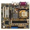
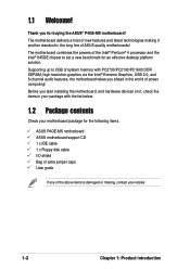
... extra jumper caps User guide If any of new features and latest technologies making it , check the items in your motherboard package for buying the ASUS® P4GE-MX motherboard! The motherboard delivers a host of the above items is damaged or missing, contact your retailer. 1-2 Chapter 1: Product introduction Supporting up to set .../PC2100/PC1600 DDR SDRAM, high-resolution graphics via the Intel® Extreme Graphics, USB 2.0, and 6-channel audio features, the motherboard takes you start installing the motherboard, and hardware devices on it another standout in the world of...
... extra jumper caps User guide If any of new features and latest technologies making it , check the items in your motherboard package for buying the ASUS® P4GE-MX motherboard! The motherboard delivers a host of the above items is damaged or missing, contact your retailer. 1-2 Chapter 1: Product introduction Supporting up to set .../PC2100/PC1600 DDR SDRAM, high-resolution graphics via the Intel® Extreme Graphics, USB 2.0, and 6-channel audio features, the motherboard takes you start installing the motherboard, and hardware devices on it another standout in the world of...
Motherboard DIY Troubleshooting Guide
Page 15
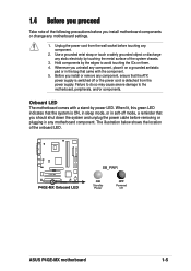
...the power cord from the power supply. Hold components by the edges to the motherboard, peripherals, and/or components. Before you install or remove any component, ensure that came with a stand-by power LED. Failure to do so may cause severe damage to ... comes with the component. 5. 1.4 Before you proceed Take note of the following precautions before you install motherboard components or change any static electricity by touching the metal surface of the onboard LED. ® P4GE-MX P4GE-MX Onboard LED SB_PWR ON Standby Power OFF Powered Off ASUS P4GE-MX motherboard 1-5
...the power cord from the power supply. Hold components by the edges to the motherboard, peripherals, and/or components. Before you install or remove any component, ensure that came with a stand-by power LED. Failure to do so may cause severe damage to ... comes with the component. 5. 1.4 Before you proceed Take note of the following precautions before you install motherboard components or change any static electricity by touching the metal surface of the onboard LED. ® P4GE-MX P4GE-MX Onboard LED SB_PWR ON Standby Power OFF Powered Off ASUS P4GE-MX motherboard 1-5
Motherboard DIY Troubleshooting Guide
Page 17
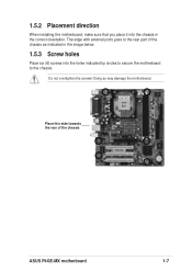
Place this side towards the rear of the chassis as indicated in the image below. 1.5.3 Screw holes Place six (6) screws into the chassis in the correct orientation. Do not overtighten the screws! Doing so may damage the motherboard. The edge with external ports goes to the chassis. 1.5.2 Placement direction When installing the motherboard, make sure that you place it into the holes indicated by circles to secure the motherboard to the rear part of the chassis ASUS P4GE-MX motherboard 1-7
Place this side towards the rear of the chassis as indicated in the image below. 1.5.3 Screw holes Place six (6) screws into the chassis in the correct orientation. Do not overtighten the screws! Doing so may damage the motherboard. The edge with external ports goes to the chassis. 1.5.2 Placement direction When installing the motherboard, make sure that you place it into the holes indicated by circles to secure the motherboard to the rear part of the chassis ASUS P4GE-MX motherboard 1-7

Motherboard DIY Troubleshooting Guide
Page 18
...are using any other operating systems, disable the Hyper-Threading Technology item in BIOS to enable the Hyper-Threading Technology item in BIOS before installing a supported operating system. 5. Take note of the CPU into the socket may bend the pins and severely damage the CPU! This ...surface mount 478-pin Zero Insertion Force (ZIF) socket designed for the Intel® Pentium® 4 processor. Gold Arrow ® P4GE-MX P4GE-MX CPU Socket 478 Incorrect installation of the marked corner (with gold triangle) on the socket to compile the code. It is supported under Windows® XP and Linux...
...are using any other operating systems, disable the Hyper-Threading Technology item in BIOS to enable the Hyper-Threading Technology item in BIOS before installing a supported operating system. 5. Take note of the CPU into the socket may bend the pins and severely damage the CPU! This ...surface mount 478-pin Zero Insertion Force (ZIF) socket designed for the Intel® Pentium® 4 processor. Gold Arrow ® P4GE-MX P4GE-MX CPU Socket 478 Incorrect installation of the marked corner (with gold triangle) on the socket to compile the code. It is supported under Windows® XP and Linux...

Motherboard DIY Troubleshooting Guide
Page 19
... the side tab to secure the CPU. otherwise, the CPU does not fit in one correct orientation. Carefully insert the CPU into the socket to install a CPU. 1. ASUS P4GE-MX motherboard 1-9 The CPU fits only in completely. 3. The lever clicks on the motherboard. 2. Unlock the socket by pressing the lever sideways, then lift it...
... the side tab to secure the CPU. otherwise, the CPU does not fit in one correct orientation. Carefully insert the CPU into the socket to install a CPU. 1. ASUS P4GE-MX motherboard 1-9 The CPU fits only in completely. 3. The lever clicks on the motherboard. 2. Unlock the socket by pressing the lever sideways, then lift it...

Motherboard DIY Troubleshooting Guide
Page 20
... severe damage to both the motherboard and the components. 1.7.2 Installing a DIMM Follow these steps to avoid damaging the DIMM. 1-10 Chapter 1: Product introduction Firmly insert the DIMM into the DIMM sockets of the DDR DIMM sockets. 80 Pins ® P4GE-MX 104 Pins P4GE-MX 184-Pin DDR DIMM Sockets Make sure to unplug the... matches the break on the socket such that it fits in place and the DIMM is properly seated. DO NOT force a DIMM into a socket to install a DIMM. 1.
... severe damage to both the motherboard and the components. 1.7.2 Installing a DIMM Follow these steps to avoid damaging the DIMM. 1-10 Chapter 1: Product introduction Firmly insert the DIMM into the DIMM sockets of the DDR DIMM sockets. 80 Pins ® P4GE-MX 104 Pins P4GE-MX 184-Pin DDR DIMM Sockets Make sure to unplug the... matches the break on the socket such that it fits in place and the DIMM is properly seated. DO NOT force a DIMM into a socket to install a DIMM. 1.
Motherboard DIY Troubleshooting Guide
Page 21
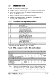
...the necessary BIOS settings, if any. used - - ASUS P4GE-MX motherboard 1-11 See Chapter 2 for this motherboard A B C D E F G H PCI slot 1 - - - - - Assign an IRQ to the tables next page. 4. 1.8 Expansion slots To install and configure an expansion card: 1. shared - - ...- - - - Refer to the card. used - shared - - - - - - Onboard USB 1.1 controller 3 - - Install the drivers and/or software applications for the expansion card according to ...
...the necessary BIOS settings, if any. used - - ASUS P4GE-MX motherboard 1-11 See Chapter 2 for this motherboard A B C D E F G H PCI slot 1 - - - - - Assign an IRQ to the tables next page. 4. 1.8 Expansion slots To install and configure an expansion card: 1. shared - - ...- - - - Refer to the card. used - shared - - - - - - Onboard USB 1.1 controller 3 - - Install the drivers and/or software applications for the expansion card according to ...

Motherboard DIY Troubleshooting Guide
Page 22
When you buy an AGP card, make sure that you ask for 1.5v P4GE-MX Accelerated Graphics Port (AGP) 1-12 Chapter 1: Product introduction Install only +1.5V AGP cards. ® P4GE-MX Keyed for one with PCI specifications. 1.8.4 AGP slot The Accelerated Graphics Port (AGP) slot supports AGP 4X (+1.5V) cards. Note the notches on the card golden fingers to ensure that they fit the AGP slot on the motherboard. 1.8.3 PCI slots The PCI slots support PCI cards such as a LAN card, SCSI card, USB card, and other cards that comply with +1.5V specification.
When you buy an AGP card, make sure that you ask for 1.5v P4GE-MX Accelerated Graphics Port (AGP) 1-12 Chapter 1: Product introduction Install only +1.5V AGP cards. ® P4GE-MX Keyed for one with PCI specifications. 1.8.4 AGP slot The Accelerated Graphics Port (AGP) slot supports AGP 4X (+1.5V) cards. Note the notches on the card golden fingers to ensure that they fit the AGP slot on the motherboard. 1.8.3 PCI slots The PCI slots support PCI cards such as a LAN card, SCSI card, USB card, and other cards that comply with +1.5V specification.
Motherboard DIY Troubleshooting Guide
Page 28
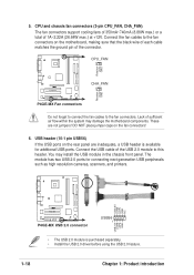
...! Connect the USB cable of the USB 2.0 module to the fan connectors on the fan connectors! 6. USB+5V LDM5 LDP5 GND NC ® P4GE-MX P4GE-MX USB 2.0 connector USB56 1 USB+5V LDM6 LDP6 GND • The USB 2.0 module is available for connecting next generation USB peripherals such as high...350mA~740mA (8.88W max.) or a total of sufficient air flow within the system may install the USB module in the chassis front panel. CPU_FAN Rotation +12V GND ® P4GE-MX CHA_FAN Rotation +12V GND P4GE-MX Fan connectors Do not forget to connect the fan cables to the fan connectors. The ...
...! Connect the USB cable of the USB 2.0 module to the fan connectors on the fan connectors! 6. USB+5V LDM5 LDP5 GND NC ® P4GE-MX P4GE-MX USB 2.0 connector USB56 1 USB+5V LDM6 LDP6 GND • The USB 2.0 module is available for connecting next generation USB peripherals such as high...350mA~740mA (8.88W max.) or a total of sufficient air flow within the system may install the USB module in the chassis front panel. CPU_FAN Rotation +12V GND ® P4GE-MX CHA_FAN Rotation +12V GND P4GE-MX Fan connectors Do not forget to connect the fan cables to the fan connectors. The ...

Motherboard DIY Troubleshooting Guide
Page 31
11. Serial connector (9-pin COM2 ) This 9-pin connector connects to a 3-pin system power LED. The LED lights up when you turn on an available slot in the rear panel of the chassis. ® P4GE-MX PIN 1 COM2 P4GE-MX Serial port connector The COM2 bracket is purchased separately. 12. PLED1 1 ASUS P4GE-MX motherboard 1-21 Power LED connector (3-pin PLED1 ) This 3-pin connector connects to a COM2 bracket. Connect the COM2 cable to this connector and install the bracket on the system power. ® P4GE-MX P4GE-MX PLED setting PLED+ NC PLED-
11. Serial connector (9-pin COM2 ) This 9-pin connector connects to a 3-pin system power LED. The LED lights up when you turn on an available slot in the rear panel of the chassis. ® P4GE-MX PIN 1 COM2 P4GE-MX Serial port connector The COM2 bracket is purchased separately. 12. PLED1 1 ASUS P4GE-MX motherboard 1-21 Power LED connector (3-pin PLED1 ) This 3-pin connector connects to a COM2 bracket. Connect the COM2 cable to this connector and install the bracket on the system power. ® P4GE-MX P4GE-MX PLED setting PLED+ NC PLED-
Motherboard DIY Troubleshooting Guide
Page 38
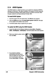
...Internet Service Provider (ISP). Insert the support CD to avoid network traffic, or choose Auto Select. Click the Utilities tab, then click Install ASUS Update VX.XX.XX. See page 5-3 for details for the Utilities menu screen. 3. If you selected updating/ downloading from the Windows.... 3. Launch the utility from the Internet, select the ASUS FTP site nearest you to update the motherboard BIOS in the support CD that allows you to the optical drive. The Drivers menu appears. 2. Select your system. Click Next. 2-6 Chapter 2: BIOS information To install ASUS Update: 1.
...Internet Service Provider (ISP). Insert the support CD to avoid network traffic, or choose Auto Select. Click the Utilities tab, then click Install ASUS Update VX.XX.XX. See page 5-3 for details for the Utilities menu screen. 3. If you selected updating/ downloading from the Windows.... 3. Launch the utility from the Internet, select the ASUS FTP site nearest you to update the motherboard BIOS in the support CD that allows you to the optical drive. The Drivers menu appears. 2. Select your system. Click Next. 2-6 Chapter 2: BIOS information To install ASUS Update: 1.
Motherboard DIY Troubleshooting Guide
Page 40
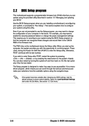
... BIOS Setup program when you may want to enable the security password feature or change the configuration of the firmware hub. Even if you are installing a motherboard, reconfiguring your BIOS." For example, you are not prompted to use as easy to use the Setup program, you may want to "Run Setup...
... BIOS Setup program when you may want to enable the security password feature or change the configuration of the firmware hub. Even if you are installing a motherboard, reconfiguring your BIOS." For example, you are not prompted to use as easy to use the Setup program, you may want to "Run Setup...
Motherboard DIY Troubleshooting Guide
Page 44
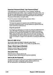
... the battery after about passwords The Supervisor password is required to [Set]. Configuration options: [Disabled] [Drive A] Video [EGA/VGA] Selects the type of floppy drive installed. The RAM data containing the password information is changed to boot the system preventing unauthorized use . Configuration options: [All Errors] [No Errors] [All, But Keyboard...
... the battery after about passwords The Supervisor password is required to [Set]. Configuration options: [Disabled] [Drive A] Video [EGA/VGA] Selects the type of floppy drive installed. The RAM data containing the password information is changed to boot the system preventing unauthorized use . Configuration options: [All Errors] [No Errors] [All, But Keyboard...
Motherboard DIY Troubleshooting Guide
Page 45
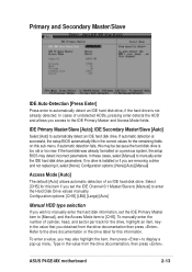
.../Slave to [Manual] to enter the Hard Disk Drive values manually. ASUS P4GE-MX motherboard 2-13 Primary and Secondary Master/Slave IDE Auto-Detection [Press Enter] Press enter to automatically detect an IDE hard disk drive, if the hard drive is installed or if you are removing a drive and not replacing it, select [None...
.../Slave to [Manual] to enter the Hard Disk Drive values manually. ASUS P4GE-MX motherboard 2-13 Primary and Secondary Master/Slave IDE Auto-Detection [Press Enter] Press enter to automatically detect an IDE hard disk drive, if the hard drive is installed or if you are removing a drive and not replacing it, select [None...

Motherboard DIY Troubleshooting Guide
Page 46
.... Precomp This item shows the precomp. After entering the IDE hard disk drive information into BIOS, use a disk utility, such as FDISK, to recognize the installed hard disk. Head This item shows the number of the Primary IDE hard disk drives to active. 2-14 Chapter 2: BIOS information Capacity [xxxxx MB] This...
.... Precomp This item shows the precomp. After entering the IDE hard disk drive information into BIOS, use a disk utility, such as FDISK, to recognize the installed hard disk. Head This item shows the number of the Primary IDE hard disk drives to active. 2-14 Chapter 2: BIOS information Capacity [xxxxx MB] This...
Motherboard DIY Troubleshooting Guide
Page 48
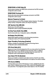
...Clock Ratio [8 X] Allows you to disable or enable the auto-detect function of the PCI clock. The configuration option values depend on the CPU installed. 2-16 Chapter 2: BIOS information To do so, highlight the item then press to display a pop-up menu. Enter a value from the ...the DRAM active command and the R/W command. The configuration option values depend on the CPU installed. Configuration options: [PC100] [PC133] [Auto] AGP Aperture Size (MB) [64] Sets the size of the device installed. When enabled, the bus speed is [Auto]. Auto Detect PCI Clk [Enabled] Allows you...
...Clock Ratio [8 X] Allows you to disable or enable the auto-detect function of the PCI clock. The configuration option values depend on the CPU installed. 2-16 Chapter 2: BIOS information To do so, highlight the item then press to display a pop-up menu. Enter a value from the ...the DRAM active command and the R/W command. The configuration option values depend on the CPU installed. Configuration options: [PC100] [PC133] [Auto] AGP Aperture Size (MB) [64] Sets the size of the device installed. When enabled, the bus speed is [Auto]. Auto Detect PCI Clk [Enabled] Allows you...
Motherboard DIY Troubleshooting Guide
Page 49
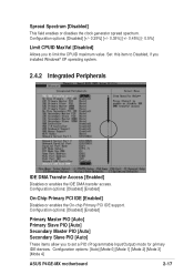
... a PIO (Programmable Input/Output) mode for primary IDE devices. Configuration options: [Auto] [Mode 0] [Mode 1] [Mode 2] [Mode 3] [Mode 4] ASUS P4GE-MX motherboard 2-17 Set this item to limit the CPUID maximum value. Configuration options: [Disabled] [Enabled] On-Chip Primary PCI IDE [Enabled] Disables or enables ... PIO [Auto] Primary Slave PIO [Auto] Secondary Master PIO [Auto] Secondary Slave PIO [Auto] These items allow you installed Windows® XP operating system. 2.4.2 Integrated Peripherals IDE DMA Transfer Access [Enabled] Disables or enables the IDE DMA transfer access.
... a PIO (Programmable Input/Output) mode for primary IDE devices. Configuration options: [Auto] [Mode 0] [Mode 1] [Mode 2] [Mode 3] [Mode 4] ASUS P4GE-MX motherboard 2-17 Set this item to limit the CPUID maximum value. Configuration options: [Disabled] [Enabled] On-Chip Primary PCI IDE [Enabled] Disables or enables ... PIO [Auto] Primary Slave PIO [Auto] Secondary Master PIO [Auto] Secondary Slave PIO [Auto] These items allow you installed Windows® XP operating system. 2.4.2 Integrated Peripherals IDE DMA Transfer Access [Enabled] Disables or enables the IDE DMA transfer access.


