Motherboard DIY Troubleshooting Guide
Page 1
P4BP-MX Motherboard
P4BP-MX Motherboard

P4BP-MX User Manual
Page 1
Motherboard P4BP-MX User Guide
Motherboard P4BP-MX User Guide
P4BP-MX User Manual
Page 3
... Notices v Safety information vi About this guide vii Conventions used in this guide vii Typography vii P4BP-MX specifications summary viii Chapter 1: Product introduction 1.1 Welcome 1-2 1.2 Package contents 1-2 1.3 Special features 1-3 1.3.1 Product Highlights 1-3 1.3.2 Unique ASUS features 1-4 1.4 Before you proceed 1-5 1.5 Motherboard overview 1-6 1.5.1 Motherboard layout 1-6 1.5.2 Placement direction 1-7 1.5.3 Screw holes 1-7 1.6 Central Processing Unit (CPU 1-8 1.6.1 Overview 1-8 1.6.2 Installing the CPU 1-9 1.7 System memory...
... Notices v Safety information vi About this guide vii Conventions used in this guide vii Typography vii P4BP-MX specifications summary viii Chapter 1: Product introduction 1.1 Welcome 1-2 1.2 Package contents 1-2 1.3 Special features 1-3 1.3.1 Product Highlights 1-3 1.3.2 Unique ASUS features 1-4 1.4 Before you proceed 1-5 1.5 Motherboard overview 1-6 1.5.1 Motherboard layout 1-6 1.5.2 Placement direction 1-7 1.5.3 Screw holes 1-7 1.6 Central Processing Unit (CPU 1-8 1.6.1 Overview 1-8 1.6.2 Installing the CPU 1-9 1.7 System memory...
P4BP-MX User Manual
Page 6
..., contact your retailer. If you are not sure about the voltage of the electrical outlet you are not damaged. Operation safety • Before installing the motherboard and adding devices on a stable surface. • If you encounter technical problems with the package. • Before using the product, make sure all cables are... are unplugged before the signal cables are unplugged. • Seek professional assistance before you add a device. • Before connecting or removing signal cables from the motherboard, ensure that all power cables are connected.
..., contact your retailer. If you are not sure about the voltage of the electrical outlet you are not damaged. Operation safety • Before installing the motherboard and adding devices on a stable surface. • If you encounter technical problems with the package. • Before using the product, make sure all cables are... are unplugged before the signal cables are unplugged. • Seek professional assistance before you add a device. • Before connecting or removing signal cables from the motherboard, ensure that all power cables are connected.
P4BP-MX User Manual
Page 11
It includes brief descriptions of the motherboard components, and illustrations of the motherboard. Chapter 1 This chapter describes the features of the layout, jumper settings, and connectors. Product introduction
It includes brief descriptions of the motherboard components, and illustrations of the motherboard. Chapter 1 This chapter describes the features of the layout, jumper settings, and connectors. Product introduction
P4BP-MX User Manual
Page 12
... list below. 1.2 Package contents Check your motherboard package for buying the ASUS® P4BP-MX motherboard! Before you start installing the motherboard, and hardware devices on it another standout in your retailer. 1-2 Chapter 1: Product introduction The motherboard delivers a host of new features and latest... SDRAM, high-resolution graphics via an AGP 8X slot, USB 2.0, and 6-channel audio features, the motherboard takes you for the following items. ASUS P4BP-MX motherboard ASUS motherboard support CD 1 x IDE cable 1 x Floppy disk cable I/O shield Bag of extra jumper caps User guide...
... list below. 1.2 Package contents Check your motherboard package for buying the ASUS® P4BP-MX motherboard! Before you start installing the motherboard, and hardware devices on it another standout in your retailer. 1-2 Chapter 1: Product introduction The motherboard delivers a host of new features and latest... SDRAM, high-resolution graphics via an AGP 8X slot, USB 2.0, and 6-channel audio features, the motherboard takes you for the following items. ASUS P4BP-MX motherboard ASUS motherboard support CD 1 x IDE cable 1 x Floppy disk cable I/O shield Bag of extra jumper caps User guide...
P4BP-MX User Manual
Page 13
... realistic 3D/2D graphics with 512/256KB L2 cache on USB 2.0 - 1.3 Special features 1.3.1 Product Highlights Latest processor technology The motherboard comes with a 478-pin surface mount, Zero Insertion Force (ZIF) socket for the Intel® Pentium® 4 processor in.... USB 2.0 is backward compatible with digital connectivity to powerful speaker systems. ASUS P4BP-MX motherboard 1-3 The higher bandwidth of USB 2.0 allows connection of 10/100 Mbps Fast Ethernet LAN. S/PDIF out The motherboard supports S/PDIF-out function turns your computer into a high-end entertainment system...
... realistic 3D/2D graphics with 512/256KB L2 cache on USB 2.0 - 1.3 Special features 1.3.1 Product Highlights Latest processor technology The motherboard comes with a 478-pin surface mount, Zero Insertion Force (ZIF) socket for the Intel® Pentium® 4 processor in.... USB 2.0 is backward compatible with digital connectivity to powerful speaker systems. ASUS P4BP-MX motherboard 1-3 The higher bandwidth of USB 2.0 allows connection of 10/100 Mbps Fast Ethernet LAN. S/PDIF out The motherboard supports S/PDIF-out function turns your computer into a high-end entertainment system...

P4BP-MX User Manual
Page 14
...or boot from a floppy disk. No need to overclocking. ASUS MyLogo™ This new feature present in case the system hangs due to buy a replacement ROM chip. C.P.R. (CPU Parameter Recall) The C.P.R. feature of the motherboard BIOS allows automatic re-setting to the BIOS previous settings in... the motherboard allows you to personalize and add style to restore the original BIOS data froma bootable floppy disk ...
...or boot from a floppy disk. No need to overclocking. ASUS MyLogo™ This new feature present in case the system hangs due to buy a replacement ROM chip. C.P.R. (CPU Parameter Recall) The C.P.R. feature of the motherboard BIOS allows automatic re-setting to the BIOS previous settings in... the motherboard allows you to personalize and add style to restore the original BIOS data froma bootable floppy disk ...
P4BP-MX User Manual
Page 15
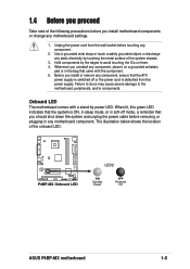
...green LED indicates that came with a stand-by touching the metal surface of the system chassis. 3. P4BP-MX P4BP-MX Onboard LED LED2 ON Standby Power OFF Powered Off ASUS P4BP-MX motherboard 1-5 Use a grounded wrist strap or touch a safely grounded object or discharge any static electricity by... power LED. Hold components by the edges to the motherboard, peripherals, and/or components. 1.4 Before ...
...green LED indicates that came with a stand-by touching the metal surface of the system chassis. 3. P4BP-MX P4BP-MX Onboard LED LED2 ON Standby Power OFF Powered Off ASUS P4BP-MX motherboard 1-5 Use a grounded wrist strap or touch a safely grounded object or discharge any static electricity by... power LED. Hold components by the edges to the motherboard, peripherals, and/or components. 1.4 Before ...
P4BP-MX User Manual
Page 16
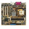
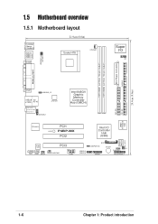
1.5 Motherboard overview 1.5.1 Motherboard layout PS/2KBMS T: Mouse B: Keyboard Bottom: USB20-3 USB20-4 COM1 21.9cm (8.6in) Socket 478 CPUFAN1 Super I/O IR1 ATX Power Connector FLOPPY1 DDR DIMM1 (64/72 ...:Line Out Below:Mic In IAPANEL1 ATX12V1 Intel 845GV Graphic Memory Controller Hub (GMCH) 01 23 SEC_IDE PRI_ IDE 2Mbit Firmware Hub RTL8101L PCI1 LED2 P4BP-MX PCI2 Intel I/O Controller Hub (ICH4) ASUS Mozart IDE_LED1 Audio Codec CD1 AUX1 SPDIF PCI3 CHASFAN1 COM2 USB20_5 USB20_6 BAT1 USBPWR_56 BUZZ1 J1 CHASSIS1 GAME1...
1.5 Motherboard overview 1.5.1 Motherboard layout PS/2KBMS T: Mouse B: Keyboard Bottom: USB20-3 USB20-4 COM1 21.9cm (8.6in) Socket 478 CPUFAN1 Super I/O IR1 ATX Power Connector FLOPPY1 DDR DIMM1 (64/72 ...:Line Out Below:Mic In IAPANEL1 ATX12V1 Intel 845GV Graphic Memory Controller Hub (GMCH) 01 23 SEC_IDE PRI_ IDE 2Mbit Firmware Hub RTL8101L PCI1 LED2 P4BP-MX PCI2 Intel I/O Controller Hub (ICH4) ASUS Mozart IDE_LED1 Audio Codec CD1 AUX1 SPDIF PCI3 CHASFAN1 COM2 USB20_5 USB20_6 BAT1 USBPWR_56 BUZZ1 J1 CHASSIS1 GAME1...
P4BP-MX User Manual
Page 17
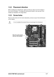
1.5.2 Placement direction When installing the motherboard, make sure that you place it into the chassis in the image below. 1.5.3 Screw holes Place six (6) screws into the holes indicated by circles to secure the motherboard to the rear part of the chassis ASUS P4BP-MX motherboard 1-7 Doing so may damage the motherboard. The edge with external ports goes to the chassis. Place this side towards the rear of the chassis as indicated in the correct orientation. Do not overtighten the screws!
1.5.2 Placement direction When installing the motherboard, make sure that you place it into the chassis in the image below. 1.5.3 Screw holes Place six (6) screws into the holes indicated by circles to secure the motherboard to the rear part of the chassis ASUS P4BP-MX motherboard 1-7 Doing so may damage the motherboard. The edge with external ports goes to the chassis. Place this side towards the rear of the chassis as indicated in the correct orientation. Do not overtighten the screws!

P4BP-MX User Manual
Page 18
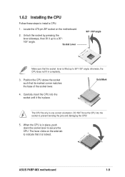
1.6 Central Processing Unit (CPU) 1.6.1 Overview The motherboard comes with Hyper-Threading Technology. 2. Gold Arrow P4BP-MX P4BP-MX Socket 478 Incorrect installation of the marked corner (with gold triangle) on the socket to ensure correct installation. For more ...Hyper-Threading compliler to ensure system stability and performance. 3. Make sure to enable the Hyper-Threading Technology item in BIOS to compile the code. This motherboard supports Intel® Pentium® 4 CPUs with a surface mount 478-pin Zero Insertion Force (ZIF) socket designed for the Intel® Pentium...
1.6 Central Processing Unit (CPU) 1.6.1 Overview The motherboard comes with Hyper-Threading Technology. 2. Gold Arrow P4BP-MX P4BP-MX Socket 478 Incorrect installation of the marked corner (with gold triangle) on the socket to ensure correct installation. For more ...Hyper-Threading compliler to ensure system stability and performance. 3. Make sure to enable the Hyper-Threading Technology item in BIOS to compile the code. This motherboard supports Intel® Pentium® 4 CPUs with a surface mount 478-pin Zero Insertion Force (ZIF) socket designed for the Intel® Pentium...
P4BP-MX User Manual
Page 19
... CPU does not fit in place, push down the socket lever to install a CPU. 1. The lever clicks on the motherboard. 2. Gold Mark 4. 1.6.2 Installing the CPU Follow these steps to secure the CPU. ASUS P4BP-MX motherboard 1-9 Unlock the socket by pressing the lever sideways, then lift it fits in one correct orientation. When the CPU...
... CPU does not fit in place, push down the socket lever to install a CPU. 1. The lever clicks on the motherboard. 2. Gold Mark 4. 1.6.2 Installing the CPU Follow these steps to secure the CPU. ASUS P4BP-MX motherboard 1-9 Unlock the socket by pressing the lever sideways, then lift it fits in one correct orientation. When the CPU...
P4BP-MX User Manual
Page 20
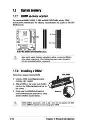
...P4BP-MX 104 Pins P4BP-MX 184-Pin DDR DIMM Sockets Make sure to install a DIMM. 1. DDR DIMM Unlocked A DDR DIMM is properly seated. Unlock a DIMM socket by pressing the retaining clips outward. 2. Align a DIMM on the socket. 3. Failure to do so may cause severe damage to both the motherboard... steps to unplug the power supply before adding or removing DIMMs or other system components. The following figure illustrates the location of this motherboard. 1.7 System memory 1.7.1 DIMM sockets location You can install 64MB, 256MB, 512MB, and 1GB DDR DIMMs into the socket until the...
...P4BP-MX 104 Pins P4BP-MX 184-Pin DDR DIMM Sockets Make sure to install a DIMM. 1. DDR DIMM Unlocked A DDR DIMM is properly seated. Unlock a DIMM socket by pressing the retaining clips outward. 2. Align a DIMM on the socket. 3. Failure to do so may cause severe damage to both the motherboard... steps to unplug the power supply before adding or removing DIMMs or other system components. The following figure illustrates the location of this motherboard. 1.7 System memory 1.7.1 DIMM sockets location You can install 64MB, 256MB, 512MB, and 1GB DDR DIMMs into the socket until the...
P4BP-MX User Manual
Page 21
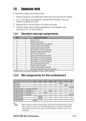
... IDE controller (dual fifo) 15 Secondary Ultra ATA Controller (dual fifo) *These IRQs are usually available for ISA or PCI devices. 1.8.2 IRQ assignments for this motherboard A B C D E F G H PCI slot 1 - - - - - PCI slot 3 shared Onboard USB 1.1 controller 1shared Onboard USB 1.1 controller 2 - - -...- - - used - - - - Onboard VGA shared When using PCI cards on the system and change the necessary BIOS settings, if any. ASUS P4BP-MX motherboard 1-11 See Chapter 2 for the expansion card according to the card. PCI slot 2 - - - - - - used - - Otherwise, ...
... IDE controller (dual fifo) 15 Secondary Ultra ATA Controller (dual fifo) *These IRQs are usually available for ISA or PCI devices. 1.8.2 IRQ assignments for this motherboard A B C D E F G H PCI slot 1 - - - - - PCI slot 3 shared Onboard USB 1.1 controller 1shared Onboard USB 1.1 controller 2 - - -...- - - used - - - - Onboard VGA shared When using PCI cards on the system and change the necessary BIOS settings, if any. ASUS P4BP-MX motherboard 1-11 See Chapter 2 for the expansion card according to the card. PCI slot 2 - - - - - - used - - Otherwise, ...
P4BP-MX User Manual
Page 23
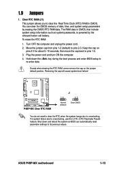
1.9 Jumpers 1. Plug the power cord and turn ON the computer. 4. P4BP-MX P4BP-MX Clear RTC RAM J1 12 23 Normal (Default) Clear CMOS You do not need to clear the RTC when the system hangs due to pins 2-3. ... down the key during the boot process and enter BIOS setup to its previous values. You can automatically reset parameter settings to re-enter data. ASUS P4BP-MX motherboard 1-13 Turn OFF the computer and unplug the power cord. 2. Except when clearing the RTC RAM, never remove the cap on pins 2-3 for about 5~10...
1.9 Jumpers 1. Plug the power cord and turn ON the computer. 4. P4BP-MX P4BP-MX Clear RTC RAM J1 12 23 Normal (Default) Clear CMOS You do not need to clear the RTC when the system hangs due to pins 2-3. ... down the key during the boot process and enter BIOS setup to its previous values. You can automatically reset parameter settings to re-enter data. ASUS P4BP-MX motherboard 1-13 Turn OFF the computer and unplug the power cord. 2. Except when clearing the RTC RAM, never remove the cap on pins 2-3 for about 5~10...
P4BP-MX User Manual
Page 25
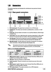
... 6-channel mode, the function of this jack becomes Bass/Center. 5. This port connects to a Local Area Network (LAN) through a network hub. 4. ASUS P4BP-MX motherboard 1-15 1.10 Connectors This section describes and illustrates the motherboard rear panel and internal connectors. 1.10.1 Rear panel connectors 1 2 3 4 5 6 11 10 9 8 7 1. This Line Out (lime) jack connects a headphone or a speaker...
... 6-channel mode, the function of this jack becomes Bass/Center. 5. This port connects to a Local Area Network (LAN) through a network hub. 4. ASUS P4BP-MX motherboard 1-15 1.10 Connectors This section describes and illustrates the motherboard rear panel and internal connectors. 1.10.1 Rear panel connectors 1 2 3 4 5 6 11 10 9 8 7 1. This Line Out (lime) jack connects a headphone or a speaker...
P4BP-MX User Manual
Page 26
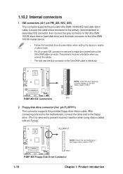
... zigzag) on the IDE ribbon cable to PIN 1. Floppy disk drive connector (34-1 pin FLOPPY1) This connector supports the provided floppy drive ribbon cable. P4BP-MX IDE Connectors PIN 1 2. This prevents incorrect orientation when you connect the cables. • The hole near the blue connector on the Ultra DMA cable ... setting the device in master or slave mode. • Pin 20 on the floppy ribbon cable to PIN 1. After connecting one end to the motherboard, connect the other end to the floppy drive. (Pin 5 is removed to match the covered hole on the Ultra DMA cable is removed to...
... zigzag) on the IDE ribbon cable to PIN 1. Floppy disk drive connector (34-1 pin FLOPPY1) This connector supports the provided floppy drive ribbon cable. P4BP-MX IDE Connectors PIN 1 2. This prevents incorrect orientation when you connect the cables. • The hole near the blue connector on the Ultra DMA cable ... setting the device in master or slave mode. • Pin 20 on the floppy ribbon cable to PIN 1. After connecting one end to the motherboard, connect the other end to the floppy drive. (Pin 5 is removed to match the covered hole on the Ultra DMA cable is removed to...
P4BP-MX User Manual
Page 27
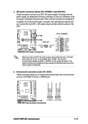
..., or 300W for a fully configured system. Left Audio Channel Ground Ground Right Audio Channel Left Audio Channel Ground Ground Right Audio Channel P4BP-MX CD1(Black) AUX1(White) P4BP-MX Internal Audio Connectors ASUS P4BP-MX motherboard 1-17 ATX power connectors (20-pin ATX_POWER1, 4-pin ATX12V1) These connectors connect to fit these connectors in only one orientation. The...
..., or 300W for a fully configured system. Left Audio Channel Ground Ground Right Audio Channel Left Audio Channel Ground Ground Right Audio Channel P4BP-MX CD1(Black) AUX1(White) P4BP-MX Internal Audio Connectors ASUS P4BP-MX motherboard 1-17 ATX power connectors (20-pin ATX_POWER1, 4-pin ATX12V1) These connectors connect to fit these connectors in only one orientation. The...

P4BP-MX User Manual
Page 28
... is purchased separately. • Install the USB 2.0 driver before using the USB 2.0 feature. 1-18 Chapter 1: Product introduction You may damage the motherboard components. USB+5V LDM5 LDP5 GND NC P4BP-MX P4BP-MX USB 2.0 Header USB1 1 USB+5V LDM6 LDP6 GND • The USB 2.0 module is available for connecting next generation USB peripherals such as...
... is purchased separately. • Install the USB 2.0 driver before using the USB 2.0 feature. 1-18 Chapter 1: Product introduction You may damage the motherboard components. USB+5V LDM5 LDP5 GND NC P4BP-MX P4BP-MX USB 2.0 Header USB1 1 USB+5V LDM6 LDP6 GND • The USB 2.0 module is available for connecting next generation USB peripherals such as...


