
Motherboard DIY Troubleshooting Guide
Page 1
Motherboard P4BGL-MX User Guide
Motherboard P4BGL-MX User Guide
Motherboard DIY Troubleshooting Guide
Page 3
... 1-2 1.2 Package contents 1-2 1.3 Introduction 1-3 1.4 Motherboard components 1-3 1.5 Motherboard layout 1-6 1.6 Before you proceed 1-7 1.7 Central Processing Unit (CPU 1-7 1.8 System memory 1-8 1.9 Expansion Slots 1-9 1.9.1 Configuring an expansion card 1-9 1.9.2 Standard ...BIOS Setup Program 2-7 2.2.1 BIOS menu bar 2-7 2.2.2 Legend bar 2-8 iii BIOS Information 2-1 2.1 Managing and updating your BIOS 2-2 2.1.1 Using ASUS EZ FLASH to update the BIOS 2-2 2.1.2 Using ASUS AFLASH to find more information vii ASUS contact information vii Specifications summary ix Chapter 1 -
... 1-2 1.2 Package contents 1-2 1.3 Introduction 1-3 1.4 Motherboard components 1-3 1.5 Motherboard layout 1-6 1.6 Before you proceed 1-7 1.7 Central Processing Unit (CPU 1-7 1.8 System memory 1-8 1.9 Expansion Slots 1-9 1.9.1 Configuring an expansion card 1-9 1.9.2 Standard ...BIOS Setup Program 2-7 2.2.1 BIOS menu bar 2-7 2.2.2 Legend bar 2-8 iii BIOS Information 2-1 2.1 Managing and updating your BIOS 2-2 2.1.1 Using ASUS EZ FLASH to update the BIOS 2-2 2.1.2 Using ASUS AFLASH to find more information vii ASUS contact information vii Specifications summary ix Chapter 1 -

Motherboard DIY Troubleshooting Guide
Page 6
...• Seek professional assistance before the signal cables are using an adpater or extension cord. Operation safety • Before installing the motherboard and adding devices on it, carefully read all the manuals that your power supply is broken, do not try to the correct ...you are not sure about the voltage of the electrical outlet you add a device. • Before connecting or removing signal cables from the motherboard, ensure that the power cables for the devices are unplugged before using , contact your retailer. Contact a qualified service technician or your local...
...• Seek professional assistance before the signal cables are using an adpater or extension cord. Operation safety • Before installing the motherboard and adding devices on it, carefully read all the manuals that your power supply is broken, do not try to the correct ...you are not sure about the voltage of the electrical outlet you add a device. • Before connecting or removing signal cables from the motherboard, ensure that the power cables for the devices are unplugged before using , contact your retailer. Contact a qualified service technician or your local...

Motherboard DIY Troubleshooting Guide
Page 11
Chapter 1 This chapter gives information about the ASUS P4BGL-MX motherboard that came with the system.This chapter includes the motherboard layout, jumper settings, and connector locations. Motherboard Info ASUS P4BGL-MX Motherboard 1-1
Chapter 1 This chapter gives information about the ASUS P4BGL-MX motherboard that came with the system.This chapter includes the motherboard layout, jumper settings, and connector locations. Motherboard Info ASUS P4BGL-MX Motherboard 1-1

Motherboard DIY Troubleshooting Guide
Page 12
... caps User Guide I/O Shield If any of ASUS quality motherboards! The ASUS P4BGL-MX motherboard is damaged or missing, contact your ASUS P4BGL-MX package for the following items. ASUS P4BGL-MX motherboard Micro-ATX form factor: 8.6 in x 9.6 in ASUS P4BGL-MX series support CD 40-conductor IDE cable Ribbon cable for buying the ASUS® P4BGL-MX motherboard! Thank you start installing the motherboard, and hardware devices on it, check...
... caps User Guide I/O Shield If any of ASUS quality motherboards! The ASUS P4BGL-MX motherboard is damaged or missing, contact your ASUS P4BGL-MX package for the following items. ASUS P4BGL-MX motherboard Micro-ATX form factor: 8.6 in x 9.6 in ASUS P4BGL-MX series support CD 40-conductor IDE cable Ribbon cable for buying the ASUS® P4BGL-MX motherboard! Thank you start installing the motherboard, and hardware devices on it, check...

Motherboard DIY Troubleshooting Guide
Page 13
1.3 Introduction The ASUS P4BGL-MX motherboard is loaded with value-added features for guaranteed consumer satisfaction. For future upgrades or system reconfiguration, this chapter provides technical information about the motherboard. 1.4 Motherboard components 1 23 4 56 7 8 14 13 12 15 16 25 24 23 22 ASUS P4BGL-MX Motherboard 9 10 11 17 18 19 20 21 1-3 This motherboard is yet another high-quality motherboard from ASUS.
1.3 Introduction The ASUS P4BGL-MX motherboard is loaded with value-added features for guaranteed consumer satisfaction. For future upgrades or system reconfiguration, this chapter provides technical information about the motherboard. 1.4 Motherboard components 1 23 4 56 7 8 14 13 12 15 16 25 24 23 22 ASUS P4BGL-MX Motherboard 9 10 11 17 18 19 20 21 1-3 This motherboard is yet another high-quality motherboard from ASUS.

Motherboard DIY Troubleshooting Guide
Page 14
...system functions that allows 3.2 GB/s data transfer rates. 3 NorthBridge Controller. The chipset supports a high-performance floppy disk controller for two PCI Slots. 11 ASUS ASIC. These two 184-pin DIMM sockets support up to four Ultra DMA 100/66, PIO Modes 3 & 4 IDE devices. These dual-channel bus ...-ECC PC2100/1600 DDR SDRAM DIMMs with 400 MHz system bus that include hardware and system voltage monitoring among others. 1-4 Chapter 1: Motherboard Information 1 ATX 12V connector. This power connector connects the 4-pin 12V plug from the ATX 12V power supply. 2 CPU Sockets.
...system functions that allows 3.2 GB/s data transfer rates. 3 NorthBridge Controller. The chipset supports a high-performance floppy disk controller for two PCI Slots. 11 ASUS ASIC. These two 184-pin DIMM sockets support up to four Ultra DMA 100/66, PIO Modes 3 & 4 IDE devices. These dual-channel bus ...-ECC PC2100/1600 DDR SDRAM DIMMs with 400 MHz system bus that include hardware and system voltage monitoring among others. 1-4 Chapter 1: Motherboard Information 1 ATX 12V connector. This power connector connects the 4-pin 12V plug from the ATX 12V power supply. 2 CPU Sockets.
Motherboard DIY Troubleshooting Guide
Page 15
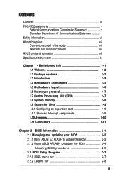
... 6-pin connector is AC '97 compliant. 13 PCI slots. This Line In (light blue) jack connects a tape player or other devices. 17 RJ-45 port. ASUS P4BGL-MX Motherboard 1-5 This audio CODEC is for a PS/2 keyboard. This port connects a VGA monitor. 23 Serial port. This port connects to a Local Area Network (LAN) through a network...
... 6-pin connector is AC '97 compliant. 13 PCI slots. This Line In (light blue) jack connects a tape player or other devices. 17 RJ-45 port. ASUS P4BGL-MX Motherboard 1-5 This audio CODEC is for a PS/2 keyboard. This port connects a VGA monitor. 23 Serial port. This port connects to a Local Area Network (LAN) through a network...

Motherboard DIY Troubleshooting Guide
Page 16
These components are optional. 24.4cm (9.6in) 1.5 Motherboard layout 21.9cm (8.6in) PS/2KBMS T: Mouse B: Keyboard Bottom: USB20-3 USB20-4 COM1 Socket 478 CPUFAN1 Super I/O IR1 ATX Power Connector FLOPPY1 DDR DIMM1 ...Memory Controller Hub (GMCH) 01 23 SEC_IDE PRI_ IDE RTL8101L ASPDIF1 PCI1 P4BGL-MX PCI2 Intel I/O Controller Hub (ICH4) ASUS Mozart Audio PCI3 Codec CD1 AUX1 CHASFAN1 COM2 USB20_5 USB20_6 BAT1 USBPWR_56 BUZZ1 CHASSIS1 J1 GAME1 ASUS PANEL1 The audio and LAN features are grayed out in the above motherboard layout. 1-6 Chapter 1: Motherboard Information
These components are optional. 24.4cm (9.6in) 1.5 Motherboard layout 21.9cm (8.6in) PS/2KBMS T: Mouse B: Keyboard Bottom: USB20-3 USB20-4 COM1 Socket 478 CPUFAN1 Super I/O IR1 ATX Power Connector FLOPPY1 DDR DIMM1 ...Memory Controller Hub (GMCH) 01 23 SEC_IDE PRI_ IDE RTL8101L ASPDIF1 PCI1 P4BGL-MX PCI2 Intel I/O Controller Hub (ICH4) ASUS Mozart Audio PCI3 Codec CD1 AUX1 CHASFAN1 COM2 USB20_5 USB20_6 BAT1 USBPWR_56 BUZZ1 CHASSIS1 J1 GAME1 ASUS PANEL1 The audio and LAN features are grayed out in the above motherboard layout. 1-6 Chapter 1: Motherboard Information
Motherboard DIY Troubleshooting Guide
Page 17
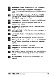
... (ZIF) socket. This socket is detached from the wall socket before touching any motherboard settings. 1. 1.6 Before you proceed Take note of the following precautions before you uninstall...motherboard comes with the component. 5. Failure to do so may cause severe damage to avoid touching the ICs on a grounded antistatic pad or in the bag that the ATX power supply is switched off or the power cord is specifically designed for the Intel® Pentium® 4 478/Northwood Processor. P4BGL-MX P4BGL-MX... Socket 478 Gold Arrow ASUS P4BGL-MX Motherboard 1-7
... (ZIF) socket. This socket is detached from the wall socket before touching any motherboard settings. 1. 1.6 Before you proceed Take note of the following precautions before you uninstall...motherboard comes with the component. 5. Failure to do so may cause severe damage to avoid touching the ICs on a grounded antistatic pad or in the bag that the ATX power supply is switched off or the power cord is specifically designed for the Intel® Pentium® 4 478/Northwood Processor. P4BGL-MX P4BGL-MX... Socket 478 Gold Arrow ASUS P4BGL-MX Motherboard 1-7

Motherboard DIY Troubleshooting Guide
Page 18
... a DIMM into a socket to the tables below. 3. Refer to avoid damaging the DIMM. 1.9 Expansion slots The P4BGL-MX motherboard has three (3) expansion slots. Assign an IRQ to 2GB non-ECC PC2100/1600 DDR. 80 Pins P4BGL-MX 104 Pins P4BGL-MX 184-Pin DDR DIMM Sockets 1. The following sub-sections describe the slots and the expansion cards...
... a DIMM into a socket to the tables below. 3. Refer to avoid damaging the DIMM. 1.9 Expansion slots The P4BGL-MX motherboard has three (3) expansion slots. Assign an IRQ to 2GB non-ECC PC2100/1600 DDR. 80 Pins P4BGL-MX 104 Pins P4BGL-MX 184-Pin DDR DIMM Sockets 1. The following sub-sections describe the slots and the expansion cards...
Motherboard DIY Troubleshooting Guide
Page 19
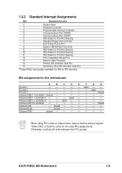
... - Onboard USB 2.0 controller shared Onboard LAN - shared - - - - - - Otherwise, conflicts will arise between two PCI groups. used - - ASUS P4BGL-MX Motherboard 1-9 PCI slot 2 - - - - - - 1.9.2 Standard Interrupt Assignments IRQ Standard Function 0 System Timer 1 Keyboard Controller 2 Programmable Interrupt Controller 3 ...Data Processor 14 Primary IDE controller (dual fifo) 15 Secondary Ultra ATA Controller (dual fifo) *These IRQs are usually available for this motherboard A B C D E F G H PCI slot 1 - - - - - used - - - - - Onboard VGA ...
... - Onboard USB 2.0 controller shared Onboard LAN - shared - - - - - - Otherwise, conflicts will arise between two PCI groups. used - - ASUS P4BGL-MX Motherboard 1-9 PCI slot 2 - - - - - - 1.9.2 Standard Interrupt Assignments IRQ Standard Function 0 System Timer 1 Keyboard Controller 2 Programmable Interrupt Controller 3 ...Data Processor 14 Primary IDE controller (dual fifo) 15 Secondary Ultra ATA Controller (dual fifo) *These IRQs are usually available for this motherboard A B C D E F G H PCI slot 1 - - - - - used - - - - - Onboard VGA ...

Motherboard DIY Troubleshooting Guide
Page 20
... capability (+5VSB) whether under normal condition or in low power mode) using the connected USB devices. P4BGL-MX USBPWR_34 3 2 2 1 +5V (Default) +5VSB USBPWR_12 USBPWR_56 12 23 +5V P4BGL-MX USB Device Wake Up (Default) +5VSB 1-10 Chapter 1: Motherboard Information 1.10 Jumpers This section describes and illustrates the jumpers on the +5VSB lead when these jumpers... up the computer from S3 sleep mode (no power to wake up . This feature requires a power supply that can provide at least 1A on the motherboard. 1.
... capability (+5VSB) whether under normal condition or in low power mode) using the connected USB devices. P4BGL-MX USBPWR_34 3 2 2 1 +5V (Default) +5VSB USBPWR_12 USBPWR_56 12 23 +5V P4BGL-MX USB Device Wake Up (Default) +5VSB 1-10 Chapter 1: Motherboard Information 1.10 Jumpers This section describes and illustrates the jumpers on the +5VSB lead when these jumpers... up the computer from S3 sleep mode (no power to wake up . This feature requires a power supply that can provide at least 1A on the motherboard. 1.
Motherboard DIY Troubleshooting Guide
Page 21
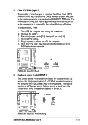
.... Set this jumper to pins 2-3 (+5VSB) if you wish to clear the Real Time Clock (RTC) RAM in the BIOS. P4BGL-MX KBPWR1 2 1 +5V (Default) 3 2 +5VSB (Default) P4BGL-MX Keyboard Power Setting ASUS P4BGL-MX Motherboard 1-11 P4BGL-MX P4BGL-MX Clear RTC RAM J1 12 23 Normal (Default) Clear CMOS 3. Turn OFF the computer and unplug the power cord. 2. Re-install...
.... Set this jumper to pins 2-3 (+5VSB) if you wish to clear the Real Time Clock (RTC) RAM in the BIOS. P4BGL-MX KBPWR1 2 1 +5V (Default) 3 2 +5VSB (Default) P4BGL-MX Keyboard Power Setting ASUS P4BGL-MX Motherboard 1-11 P4BGL-MX P4BGL-MX Clear RTC RAM J1 12 23 Normal (Default) Clear CMOS 3. Turn OFF the computer and unplug the power cord. 2. Re-install...

Motherboard DIY Troubleshooting Guide
Page 22
... more than two UltraDMA100/66 devices, purchase another for the jumper settings. P4BGL-MX P4BGL-MX IDE Connectors SEC_IDE PRI_IDE NOTE: Orient the red markings (usually zigzag) on the IDE ribbon cable to match the covered hole on the motherboard. 1. PIN 1 1-12 Chapter 1: Motherboard Information IDE connectors (40-1 pin PRI_IDE, SEC_IDE) This connector supports the provided...
... more than two UltraDMA100/66 devices, purchase another for the jumper settings. P4BGL-MX P4BGL-MX IDE Connectors SEC_IDE PRI_IDE NOTE: Orient the red markings (usually zigzag) on the IDE ribbon cable to match the covered hole on the motherboard. 1. PIN 1 1-12 Chapter 1: Motherboard Information IDE connectors (40-1 pin PRI_IDE, SEC_IDE) This connector supports the provided...

Motherboard DIY Troubleshooting Guide
Page 23
... sensor or microswitch. By default, the pins labeled "Chassis Signal" and "GND" are shorted with intrusion detection feature. CHASSIS1 +5VSB_MB Chassis Signal GND P4BGL-MX P4BGL-MX Chassis Alarm Lead ASUS P4BGL-MX Motherboard 1-13 If you remove any chassis component, the sensor triggers and sends a high-level signal to this lead to prevent incorrect insertion when using...
... sensor or microswitch. By default, the pins labeled "Chassis Signal" and "GND" are shorted with intrusion detection feature. CHASSIS1 +5VSB_MB Chassis Signal GND P4BGL-MX P4BGL-MX Chassis Alarm Lead ASUS P4BGL-MX Motherboard 1-13 If you remove any chassis component, the sensor triggers and sends a high-level signal to this lead to prevent incorrect insertion when using...

Motherboard DIY Troubleshooting Guide
Page 24
...addition to the 20-pin ATXPWR connector, this motherboard requires that you will need to the front USB ports. ATX_POWER1 Pin 1 +12.0VDC +5VSB ATX12V1 PWR_OK COM P4BGL-MX +12V DC GND +12V DC GND +5.0VDC COM +5.0VDC COM +3.3VDC P4BGL-MX ATX Power Connectors +3.3VDC +5.0VDC +5.0VDC ... at least 1A on the +5-volt standby lead (+5VSB). USB+5V LDM5 LDP5 GND NC P4BGL-MX P4BGL-MX USB 2.0 Header USB20_5 USB20_6 1 USB+5V LDM6 LDP6 GND 1-14 Chapter 1: Motherboard Information Find the proper orientation and push down firmly until the connectors completely fit. The minimum recommended...
...addition to the 20-pin ATXPWR connector, this motherboard requires that you will need to the front USB ports. ATX_POWER1 Pin 1 +12.0VDC +5VSB ATX12V1 PWR_OK COM P4BGL-MX +12V DC GND +12V DC GND +5.0VDC COM +5.0VDC COM +3.3VDC P4BGL-MX ATX Power Connectors +3.3VDC +5.0VDC +5.0VDC ... at least 1A on the +5-volt standby lead (+5VSB). USB+5V LDM5 LDP5 GND NC P4BGL-MX P4BGL-MX USB 2.0 Header USB20_5 USB20_6 1 USB+5V LDM6 LDP6 GND 1-14 Chapter 1: Motherboard Information Find the proper orientation and push down firmly until the connectors completely fit. The minimum recommended...
Motherboard DIY Troubleshooting Guide
Page 25
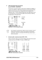
... manufacturer. Left Audio Channel Ground Ground Right Audio Channel Left Audio Channel Ground Ground Right Audio Channel P4BGL-MX CD1(Black) AUX1(White) P4BGL-MX Internal Audio Connectors ASUS P4BGL-MX Motherboard 1-15 6. The fan wiring and plug may damage the motherboard components. Orient the fans so that the heat sink fins allow you to the fan connectors. Internal...
... manufacturer. Left Audio Channel Ground Ground Right Audio Channel Left Audio Channel Ground Ground Right Audio Channel P4BGL-MX CD1(Black) AUX1(White) P4BGL-MX Internal Audio Connectors ASUS P4BGL-MX Motherboard 1-15 6. The fan wiring and plug may damage the motherboard components. Orient the fans so that the heat sink fins allow you to the fan connectors. Internal...

Motherboard DIY Troubleshooting Guide
Page 26
... playing games, and MIDI devices for playing or editing audio files. +5V J1B2 J1CY GND GND J1CX J1B1 +5V P4BGL-MX P4BGL-MX Game Connector GAME1 MIDI_IN J2B2 J2CY MIDI_OUT J2CX J2B1 +5V 1-16 Chapter 1: Motherboard Information Front panel audio connectors (10-1 pin IAPANEL1) This connector connects to this connector. If your package came with...
... playing games, and MIDI devices for playing or editing audio files. +5V J1B2 J1CY GND GND J1CX J1B1 +5V P4BGL-MX P4BGL-MX Game Connector GAME1 MIDI_IN J2B2 J2CY MIDI_OUT J2CX J2B1 +5V 1-16 Chapter 1: Motherboard Information Front panel audio connectors (10-1 pin IAPANEL1) This connector connects to this connector. If your package came with...
Motherboard DIY Troubleshooting Guide
Page 27
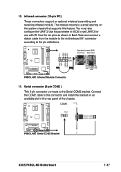
... UART2 for use with IR. 10. You must also configure the UART2 Use As parameter in the rear panel of the chassis. P4BGL-MX IRAX GND CIRRX CIR+5V +5V IRRX GND IRTX Standard Infrared (SIR) Front View Back View SIR CIR IRTX +5V GND (NC) IRRX... P4BGL-MX Infrared Module Connector 11. Connect the COM2 cable to this connector and install the bracket on an available slot in BIOS to a small opening on the system chassis that supports this feature. COM2 PIN 1 P4BGL-MX P4BGL-MX Serial COM2 Bracket ASUS P4BGL-MX Motherboard 1-17
... UART2 for use with IR. 10. You must also configure the UART2 Use As parameter in the rear panel of the chassis. P4BGL-MX IRAX GND CIRRX CIR+5V +5V IRRX GND IRTX Standard Infrared (SIR) Front View Back View SIR CIR IRTX +5V GND (NC) IRRX... P4BGL-MX Infrared Module Connector 11. Connect the COM2 cable to this connector and install the bracket on an available slot in BIOS to a small opening on the system chassis that supports this feature. COM2 PIN 1 P4BGL-MX P4BGL-MX Serial COM2 Bracket ASUS P4BGL-MX Motherboard 1-17


