Motherboard DIY Troubleshooting Guide
Page 3
... viii How this guide is organized viii Conventions used in this guide ix Where to find more information ix ASUS contact information x Chapter 1: Product introduction 1-1 1.1 Welcome 1-1 1.2 Package contents 1-1 1.3 Overview 1-2 1.3.1 ... 2-1 2.1.2 Screw holes 2-1 2.2 Motherboard layout 2-2 2.3 Before you proceed 2-3 2.4 Central Processing Unit (CPU 2-4 2.4.1 Overview 2-4 2.4.2 Installing the CPU 2-5 2.4.3 Installing the heatsink and fan 2-7 2.4.4 Connecting the CPU fan cable 2-9 2.5 System memory 2-10 2.5.1 Overview 2-10 2.5.2 Memory configurations 2-10 2.5.3 Installing a ...
... viii How this guide is organized viii Conventions used in this guide ix Where to find more information ix ASUS contact information x Chapter 1: Product introduction 1-1 1.1 Welcome 1-1 1.2 Package contents 1-1 1.3 Overview 1-2 1.3.1 ... 2-1 2.1.2 Screw holes 2-1 2.2 Motherboard layout 2-2 2.3 Before you proceed 2-3 2.4 Central Processing Unit (CPU 2-4 2.4.1 Overview 2-4 2.4.2 Installing the CPU 2-5 2.4.3 Installing the heatsink and fan 2-7 2.4.4 Connecting the CPU fan cable 2-9 2.5 System memory 2-10 2.5.1 Overview 2-10 2.5.2 Memory configurations 2-10 2.5.3 Installing a ...
Motherboard DIY Troubleshooting Guide
Page 15
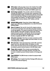
... accommodates the Intel® Pentium® 4 478/Northwood Processor with MPU-401 UART mode. 5 ATX power connector. This 20-pin connector connects to set the CPU external frequency. Both the primary (blue) and secondary (black) connectors are interconnected through the Intel proprietary Hub interface. This 2Mb firmware contains the programmable BIOS... (one of the two major components of the floppy disk cable. 8 Flash EEPROM. This Low Pin Count (LPC) chipset combines the commonly used Super I /O chipset. ASUS P4B-MX motherboard user guide 1-3 1 CPU socket.
... accommodates the Intel® Pentium® 4 478/Northwood Processor with MPU-401 UART mode. 5 ATX power connector. This 20-pin connector connects to set the CPU external frequency. Both the primary (blue) and secondary (black) connectors are interconnected through the Intel proprietary Hub interface. This 2Mb firmware contains the programmable BIOS... (one of the two major components of the floppy disk cable. 8 Flash EEPROM. This Low Pin Count (LPC) chipset combines the commonly used Super I /O chipset. ASUS P4B-MX motherboard user guide 1-3 1 CPU socket.
Motherboard DIY Troubleshooting Guide
Page 17
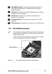
... do not have to remove the retention module base when installing the CPU or installing other devices. 25 PS/2 keyboard port. This connector supports a joystick or a game pad for playing games, and MIDI devices for pointing devices or ... PS/2 mouse port. This 25-pin port connects a parallel printer, a scanner, or other motherboard components. Retention Module Base Figure 1-2 Pre-installed Heatsink Retention Module Base ASUS P4B-MX motherboard user guide 1-5 22 Game/MIDI connector. These two 9-pin COM1/COM2 ports are for playing or editing audio files. 23 Serial ports. This module...
... do not have to remove the retention module base when installing the CPU or installing other devices. 25 PS/2 keyboard port. This connector supports a joystick or a game pad for playing games, and MIDI devices for pointing devices or ... PS/2 mouse port. This 25-pin port connects a parallel printer, a scanner, or other motherboard components. Retention Module Base Figure 1-2 Pre-installed Heatsink Retention Module Base ASUS P4B-MX motherboard user guide 1-5 22 Game/MIDI connector. These two 9-pin COM1/COM2 ports are for playing or editing audio files. 23 Serial ports. This module...

Motherboard DIY Troubleshooting Guide
Page 18
... frequency. The bus mastering capabilities permit processing of high-level commands and performing multiple operations, thereby offloading communications tasks from the CPU. 1-6 Chapter 1: Product introduction The P4 offers optimized performance for high-speed data transfers over the PCI bus. Onboard LAN ..., allowing enhanced bus mastering capabilities for audio, video, and Internet applications. 1.4 Special features Latest processor technology The P4B-MX motherboard supports the latest Intel Pentium 4 478/ Northwood Processor, also known as P4, via a 478-pin surface mount ZIF socket.
... frequency. The bus mastering capabilities permit processing of high-level commands and performing multiple operations, thereby offloading communications tasks from the CPU. 1-6 Chapter 1: Product introduction The P4 offers optimized performance for high-speed data transfers over the PCI bus. Onboard LAN ..., allowing enhanced bus mastering capabilities for audio, video, and Internet applications. 1.4 Special features Latest processor technology The P4B-MX motherboard supports the latest Intel Pentium 4 478/ Northwood Processor, also known as P4, via a 478-pin surface mount ZIF socket.

Motherboard DIY Troubleshooting Guide
Page 24
...trace cache. The Intel Pentium 4 Processor in the illustration that should match a specific corner of the CPU socket. This mark indicates the processor Pin 1 that the CPU has a gold triangular mark on one corner. Together, these attributes improve system performance by allowing higher ...Chip Pin Grid Array 2 (FC-PGA2) package technology, and includes the Intel® NetBurst™ micro-architecture. 2.4 Central Processing Unit (CPU) 2.4.1 Overview The motherboard comes with a surface mount 478-pin Zero Insertion Force (ZIF) socket. This socket is specifically designed for the ...
...trace cache. The Intel Pentium 4 Processor in the illustration that should match a specific corner of the CPU socket. This mark indicates the processor Pin 1 that the CPU has a gold triangular mark on one corner. Together, these attributes improve system performance by allowing higher ...Chip Pin Grid Array 2 (FC-PGA2) package technology, and includes the Intel® NetBurst™ micro-architecture. 2.4 Central Processing Unit (CPU) 2.4.1 Overview The motherboard comes with a surface mount 478-pin Zero Insertion Force (ZIF) socket. This socket is specifically designed for the ...

Motherboard DIY Troubleshooting Guide
Page 25
Locate the 478-pin ZIF socket on the motherboard. Unlock the socket by pressing the lever sideways, then lift it up to 90°-100° angle, otherwise the CPU does not fit in completely. ASUS P4B-MX motherboard user guide 2-5 2.4.2 Installing the CPU Follow these steps to a 90°-100° angle. Socket Lever 90 - 100 Figure 2-6 CPU Socket Lever at 90° -100° Angle Make sure that the socket lever is lifted up to install a CPU. 1. Figure 2-5 Intel 478-pin ZIF Socket 2.
Locate the 478-pin ZIF socket on the motherboard. Unlock the socket by pressing the lever sideways, then lift it up to 90°-100° angle, otherwise the CPU does not fit in completely. ASUS P4B-MX motherboard user guide 2-5 2.4.2 Installing the CPU Follow these steps to a 90°-100° angle. Socket Lever 90 - 100 Figure 2-6 CPU Socket Lever at 90° -100° Angle Make sure that the socket lever is lifted up to install a CPU. 1. Figure 2-5 Intel 478-pin ZIF Socket 2.

Motherboard DIY Troubleshooting Guide
Page 26
... the socket until it fits in place. Carefully insert the CPU into the socket to prevent bending the pins and damaging the CPU! Gold Mark Figure 2-7 Installing the CPU 5. The lever clicks on the socket while you push down the socket lever to indicate that its marked corner ...matches the base of the socket lever. 4. The CPU fits only in place, press it is in one correct orientation. When the CPU is locked. Figure 2-8 Installed CPU 2-6 Chapter 2: Hardware information 3. Position the CPU above the socket such that it firmly on the side tab to secure...
... the socket until it fits in place. Carefully insert the CPU into the socket to prevent bending the pins and damaging the CPU! Gold Mark Figure 2-7 Installing the CPU 5. The lever clicks on the socket while you push down the socket lever to indicate that its marked corner ...matches the base of the socket lever. 4. The CPU fits only in place, press it is in one correct orientation. When the CPU is locked. Figure 2-8 Installed CPU 2-6 Chapter 2: Hardware information 3. Position the CPU above the socket such that it firmly on the side tab to secure...
Motherboard DIY Troubleshooting Guide
Page 27
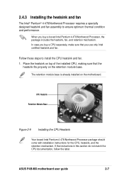
... module base is already installed on the retention module base. If the instructions in this section do not match the CPU documentation, follow the latter. ASUS P4B-MX motherboard user guide 2-7 CPU Heatsink Retention Module Base Figure 2-9 Installing the CPU Heatsink Your boxed Intel Pentium 4 478/Northwood Processor package should come with installation instructions for the...
... module base is already installed on the retention module base. If the instructions in this section do not match the CPU documentation, follow the latter. ASUS P4B-MX motherboard user guide 2-7 CPU Heatsink Retention Module Base Figure 2-9 Installing the CPU Heatsink Your boxed Intel Pentium 4 478/Northwood Processor package should come with installation instructions for the...
Motherboard DIY Troubleshooting Guide
Page 29
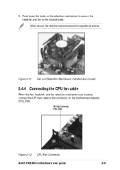
3. Figure 2-11 Fan and Retention Mechanism Installed and Locked 2.4.4 Connecting the CPU fan cable When the fan, heatsink, and the retention mechanism are in place, connect the CPU fan cable to opposite directions. CPU Fan Connector (CPU_FAN) Figure 2-12 CPU Fan Connector ASUS P4B-MX motherboard user guide 2-9 When secure, the retention locks should point to the connector on the retention mechanism to secure the heatsink and fan to the module base. Push down the locks on the motherboard labeled CPU_FAN.
3. Figure 2-11 Fan and Retention Mechanism Installed and Locked 2.4.4 Connecting the CPU fan cable When the fan, heatsink, and the retention mechanism are in place, connect the CPU fan cable to opposite directions. CPU Fan Connector (CPU_FAN) Figure 2-12 CPU Fan Connector ASUS P4B-MX motherboard user guide 2-9 When secure, the retention locks should point to the connector on the retention mechanism to secure the heatsink and fan to the module base. Push down the locks on the motherboard labeled CPU_FAN.
Motherboard DIY Troubleshooting Guide
Page 36
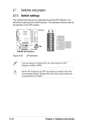
SW1801 ON OFF ON 1 2 3 4 5 6 7 8 9 10 ® P4B-MX P4B-MX DIP Switches Figure 2-20 DIP Switches 1. Reserved 3. Reserved 2. Reserved 4. Reserved 5. Set the CPU frequency and CPU bus frequency multiple only to be stable. 2-16 Chapter 2: Hardware information Settings other than those recommended are using an unlocked CPU, you may change the CPU frequency multiple in the OFF position. 2.7 Switches...
SW1801 ON OFF ON 1 2 3 4 5 6 7 8 9 10 ® P4B-MX P4B-MX DIP Switches Figure 2-20 DIP Switches 1. Reserved 3. Reserved 2. Reserved 4. Reserved 5. Set the CPU frequency and CPU bus frequency multiple only to be stable. 2-16 Chapter 2: Hardware information Settings other than those recommended are using an unlocked CPU, you may change the CPU frequency multiple in the OFF position. 2.7 Switches...
Motherboard DIY Troubleshooting Guide
Page 37
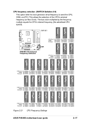
SW1801 ON 1 2 3 4 5 6 7 8 9 10 ON 1 2 3 4 5 6 7 8 9 10 ON 1 2 3 4 5 6 7 8 9 10 ® P4B-MX P4B-MX CPU External Frequency Selection CPUCLK 100.00MHz 103.00MHz 105.00MHz 3V66 66.67MHz 68.67MHz 70.00MHz PCICLK 33.33MHz 34.33MHz 35.00MHz ON 1 2 3 4 5 6 7 8 9 ... 36.25MHz 37.5MHz 38.75MHz 40.00MHz 42.50MHz 33.34MHz 33.33MHz Figure 2-21 CPU Frequency Settings ASUS P4B-MX motherboard user guide 2-17 CPU frequency selection (SWITCH Switches 5-9) This option tells the clock generator what frequency to send the CPU, 3V66, and PCI. The bus clock multiplied by the frequency multiple equals the...
SW1801 ON 1 2 3 4 5 6 7 8 9 10 ON 1 2 3 4 5 6 7 8 9 10 ON 1 2 3 4 5 6 7 8 9 10 ® P4B-MX P4B-MX CPU External Frequency Selection CPUCLK 100.00MHz 103.00MHz 105.00MHz 3V66 66.67MHz 68.67MHz 70.00MHz PCICLK 33.33MHz 34.33MHz 35.00MHz ON 1 2 3 4 5 6 7 8 9 ... 36.25MHz 37.5MHz 38.75MHz 40.00MHz 42.50MHz 33.34MHz 33.33MHz Figure 2-21 CPU Frequency Settings ASUS P4B-MX motherboard user guide 2-17 CPU frequency selection (SWITCH Switches 5-9) This option tells the clock generator what frequency to send the CPU, 3V66, and PCI. The bus clock multiplied by the frequency multiple equals the...

Motherboard DIY Troubleshooting Guide
Page 38
This jumper is set to pins 1-2 (+5V) by default. USBPWR 12 23 ® P4B-MX P4B-MX USB Device Wake-Up +5V (Default) +5VSB Figure 2-22 USB Device Wake-up . This feature requires a...this jumper to +5V to wake up the computer from S3 sleep mode (no power to wake up from S1 sleep mode (CPU stopped, DRAM refreshed, system running in low power mode) using the connected USB devices. Otherwise, the system does not power up...5VSB) whether under normal condition or in reduced power mode). 2.7.2 Jumper settings 1. Set to +5VSB to CPU, DRAM in slow refresh, power supply in sleep mode.
This jumper is set to pins 1-2 (+5V) by default. USBPWR 12 23 ® P4B-MX P4B-MX USB Device Wake-Up +5V (Default) +5VSB Figure 2-22 USB Device Wake-up . This feature requires a...this jumper to +5V to wake up the computer from S3 sleep mode (no power to wake up from S1 sleep mode (CPU stopped, DRAM refreshed, system running in low power mode) using the connected USB devices. Otherwise, the system does not power up...5VSB) whether under normal condition or in reduced power mode). 2.7.2 Jumper settings 1. Set to +5VSB to CPU, DRAM in slow refresh, power supply in sleep mode.

Motherboard DIY Troubleshooting Guide
Page 43
... caps on the fan manufacturer. CPU_FAN Rotation +12V- ® P4B-MX SYSTEM_FAN Rotation -+12V PCI_FAN Rotation +12V- Do not forget to connect the fan cables to PIN 1. ® P4B-MX P4B-MX Floppy Disk Drive Connector Figure 2-27 Floppy Disk Drive Connector 4. CPU, System, and PCI fan connectors (3-pin CPU_FAN, SYSTEM_FAN, PCI_FAN)...cable. Connect the fan cable to the connector matching the black wire to the ground pin. Lack of the expansion slots. P4B-MX 12-Volt Cooling Fan Power Figure 2-28 CPU, System, and PCI Fan Connectors ASUS P4B-MX motherboard user guide 2-23
... caps on the fan manufacturer. CPU_FAN Rotation +12V- ® P4B-MX SYSTEM_FAN Rotation -+12V PCI_FAN Rotation +12V- Do not forget to connect the fan cables to PIN 1. ® P4B-MX P4B-MX Floppy Disk Drive Connector Figure 2-27 Floppy Disk Drive Connector 4. CPU, System, and PCI fan connectors (3-pin CPU_FAN, SYSTEM_FAN, PCI_FAN)...cable. Connect the fan cable to the connector matching the black wire to the ground pin. Lack of the expansion slots. P4B-MX 12-Volt Cooling Fan Power Figure 2-28 CPU, System, and PCI Fan Connectors ASUS P4B-MX motherboard user guide 2-23
Motherboard DIY Troubleshooting Guide
Page 45
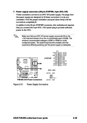
... connectors connect to the CPU. ATXPWR Pin 1 +12.0VDC +5VSB PWR_OK COM +5.0VDC COM +5.0VDC COM +3.3VDC +3.3VDC +5.0VDC +5.0VDC -5.0VDC COM COM COM PS_ON# COM -12.0VDC +3.3VDC ® P4B-MX P4B-MX ATX Power Connectors ATX +12V +12V DC COM Pin 1 +12V DC COM Figure 2-31 Power Supply Connectors ASUS P4B-MX motherboard user guide 2-25...
... connectors connect to the CPU. ATXPWR Pin 1 +12.0VDC +5VSB PWR_OK COM +5.0VDC COM +5.0VDC COM +3.3VDC +3.3VDC +5.0VDC +5.0VDC -5.0VDC COM COM COM PS_ON# COM -12.0VDC +3.3VDC ® P4B-MX P4B-MX ATX Power Connectors ATX +12V +12V DC COM Pin 1 +12V DC COM Figure 2-31 Power Supply Connectors ASUS P4B-MX motherboard user guide 2-25...

Motherboard DIY Troubleshooting Guide
Page 51
... following order: a. If you do not see anything within 30 seconds from the time you turned on the power, the system may light up . ASUS P4B-MX motherboard user guide 3-1 Turn on the system front panel case lights up or switch between orange and green after the system LED turns on the... switch. Be sure that is working Meaning No error during POST No DRAM installed or detected Video card not found or video card memory bad CPU overheated; Award BIOS Beep Codes Beep One short beep when displaying logo Long beeps in Chapter 4. External SCSI devices (starting with "green" standards ...
... following order: a. If you do not see anything within 30 seconds from the time you turned on the power, the system may light up . ASUS P4B-MX motherboard user guide 3-1 Turn on the system front panel case lights up or switch between orange and green after the system LED turns on the... switch. Be sure that is working Meaning No error during POST No DRAM installed or detected Video card not found or video card memory bad CPU overheated; Award BIOS Beep Codes Beep One short beep when displaying logo Long beeps in Chapter 4. External SCSI devices (starting with "green" standards ...
Motherboard DIY Troubleshooting Guide
Page 69
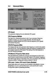
... Multiple This field is set to be in the popup menu vary according to the system frequency. Configuration options: [Disabled] [Enabled] ASUS P4B-MX motherboard user guide 4-15 4.4 Advanced Menu CPU Speed This parameter displays the auto-detected CPU speed. If your processor frequency multiple is locked, you to the system bus and PCI bus.
... Multiple This field is set to be in the popup menu vary according to the system frequency. Configuration options: [Disabled] [Enabled] ASUS P4B-MX motherboard user guide 4-15 4.4 Advanced Menu CPU Speed This parameter displays the auto-detected CPU speed. If your processor frequency multiple is locked, you to the system bus and PCI bus.
Motherboard DIY Troubleshooting Guide
Page 73
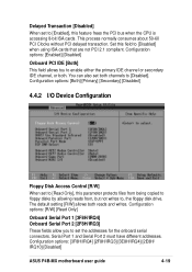
...Port 1 and Serial Port 2 must have different addresses. Configuration options: [3F8H/IRQ4] [2F8H/IRQ3] [3E8H/IRQ4] [2E8H/ IRQ10] [Disabled] ASUS P4B-MX motherboard user guide 4-19 Configuration options: [Enabled] [Disabled] Onboard PCI IDE [Both] This field allows tou to [Disabled] when using ISA cards that... are not PCI 2.1 compliant. The default setting [R/W] allows both channels to [Enabled], this feature frees the PCI bus when the CPU is accessing 8-bit ISA cards. Set this parameter protects files from being copied to floppy disks by allowing reads from, but not writes to ...
...Port 1 and Serial Port 2 must have different addresses. Configuration options: [3F8H/IRQ4] [2F8H/IRQ3] [3E8H/IRQ4] [2E8H/ IRQ10] [Disabled] ASUS P4B-MX motherboard user guide 4-19 Configuration options: [Enabled] [Disabled] Onboard PCI IDE [Both] This field allows tou to [Disabled] when using ISA cards that... are not PCI 2.1 compliant. The default setting [R/W] allows both channels to [Enabled], this feature frees the PCI bus when the CPU is accessing 8-bit ISA cards. Set this parameter protects files from being copied to floppy disks by allowing reads from, but not writes to ...
Motherboard DIY Troubleshooting Guide
Page 82
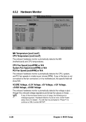
... [xxxxRPM] or N/A System Fan Speed [xxxxRPM] or N/A PCI Fan Speed [xxxxRPM] or N/A The onboard hardware monitor automatically detects the CPU, system, and PCI fan speeds in rotations per minute (RPM). VCORE Voltage, +3.3V Voltage, +5V Voltage, +12V Voltage, +3VSB Voltage, +5VSB Voltage The onboard hardware ... field will then be prompted to "Press F1 to continue or DEL to the fan connectors on these fields. 4.5.2 Hardware Monitor MB Temperature [xxxC/xxxF] CPU Temperature [xxxC/xxxF] The onboard hardware monitor automatically detects the MB (motherboard) and...
... [xxxxRPM] or N/A System Fan Speed [xxxxRPM] or N/A PCI Fan Speed [xxxxRPM] or N/A The onboard hardware monitor automatically detects the CPU, system, and PCI fan speeds in rotations per minute (RPM). VCORE Voltage, +3.3V Voltage, +5V Voltage, +12V Voltage, +3VSB Voltage, +5VSB Voltage The onboard hardware ... field will then be prompted to "Press F1 to continue or DEL to the fan connectors on these fields. 4.5.2 Hardware Monitor MB Temperature [xxxC/xxxF] CPU Temperature [xxxC/xxxF] The onboard hardware monitor automatically detects the MB (motherboard) and...
Motherboard DIY Troubleshooting Guide
Page 92
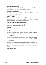
Intel® LDCM Client Setup This program is for detailed information. ASUS BIOS Flash Utility This utility allows you keep your computer at a healthy operating condition. ASUS Screen Saver This item installs the ASUS screen saver. 5-4 Chapter 5: Software support Cyberlink Video and Audio Applications This ...software is the first application that gives online gamers the competitive edge in Portable Document Format (PDF). ASUS PC Probe This smart utility monitors the fan speed, CPU temperature, and system voltages, and alerts you on any detected problems. This utility helps you to...
Intel® LDCM Client Setup This program is for detailed information. ASUS BIOS Flash Utility This utility allows you keep your computer at a healthy operating condition. ASUS Screen Saver This item installs the ASUS screen saver. 5-4 Chapter 5: Software support Cyberlink Video and Audio Applications This ...software is the first application that gives online gamers the competitive edge in Portable Document Format (PDF). ASUS PC Probe This smart utility monitors the fan speed, CPU temperature, and system voltages, and alerts you on any detected problems. This utility helps you to...
Motherboard DIY Troubleshooting Guide
Page 102
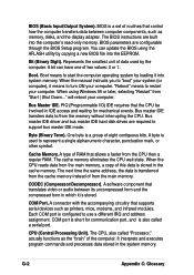
...is also called "Processor," actually functions as printers, mice, modems, and infrared modules. Bit (Binary Digit). PIO (Programmable I/O) IDE requires that the CPU be involved in the system memory. Byte (Binary Term). A type of this data is stored. Each COM port is used by copying a new... is configured to start the computer operating system by loading it is stored in the cache memory. When the CPU reads data from the memory without interrupting the CPU. A software component that supports serial devices such as the "brain" of data used to represent a single alphanumeric...
...is also called "Processor," actually functions as printers, mice, modems, and infrared modules. Bit (Binary Digit). PIO (Programmable I/O) IDE requires that the CPU be involved in the system memory. Byte (Binary Term). A type of this data is stored. Each COM port is used by copying a new... is configured to start the computer operating system by loading it is stored in the cache memory. When the CPU reads data from the memory without interrupting the CPU. A software component that supports serial devices such as the "brain" of data used to represent a single alphanumeric...


