P3V133 User Manual
Page 1
® P3V133 PC133 Motherboard USER'S MANUAL
® P3V133 PC133 Motherboard USER'S MANUAL
P3V133 User Manual
Page 4
... Solutions 28 3.6.8 Precautions 29 3.7 Expansion Cards 30 3.8 External Connectors 32 3.9 Starting Up the First Time 41 4. FEATURES 8 2.1 The ASUS P3V133 8 2.1.1 Specifications 8 2.1.2 Special Features 10 2.1.3 Performance Features 10 2.1.4 Intelligence 11 2.2 P3V133 Motherboard Components 12 3. INTRODUCTION 7 1.1 How This Manual Is Organized 7 1.2 Item Checklist 7 2. BIOS SETUP 42 4.1 Managing and Updating Your BIOS 42 4.1.1 Upon First Use of the...
... Solutions 28 3.6.8 Precautions 29 3.7 Expansion Cards 30 3.8 External Connectors 32 3.9 Starting Up the First Time 41 4. FEATURES 8 2.1 The ASUS P3V133 8 2.1.1 Specifications 8 2.1.2 Special Features 10 2.1.3 Performance Features 10 2.1.4 Intelligence 11 2.2 P3V133 Motherboard Components 12 3. INTRODUCTION 7 1.1 How This Manual Is Organized 7 1.2 Item Checklist 7 2. BIOS SETUP 42 4.1 Managing and Updating Your BIOS 42 4.1.1 Upon First Use of the...
P3V133 User Manual
Page 5
... 89 7.2.1 Features 90 7.2.2 Software Driver Support 90 7.2.3 Questions and Answers 90 7.3 Glossary 91 ASUS P3V133 User's Manual 5 SOFTWARE REFERENCE 81 6.1 ASUS PC Probe 81 7. SOFTWARE SETUP 73 5.1 Operating Systems 73 5.1.1 Windows 98 First Time Installation 73 5.2 P3V Series Motherboard Support CD 74 5.3 ASUS PC Probe Setup 75 5.4 Adobe Acrobat Reader 76 5.5 Install VIA 4 in 1 Driver 77...
... 89 7.2.1 Features 90 7.2.2 Software Driver Support 90 7.2.3 Questions and Answers 90 7.3 Glossary 91 ASUS P3V133 User's Manual 5 SOFTWARE REFERENCE 81 6.1 ASUS PC Probe 81 7. SOFTWARE SETUP 73 5.1 Operating Systems 73 5.1.1 Windows 98 First Time Installation 73 5.2 P3V Series Motherboard Support CD 74 5.3 ASUS PC Probe Setup 75 5.4 Adobe Acrobat Reader 76 5.5 Install VIA 4 in 1 Driver 77...
P3V133 User Manual
Page 7
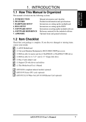
... drives (1) Bag of spare jumper caps (1) Support CD with drivers and utilities (1) This Motherboard User's Manual ASUS IrDA-compliant infrared module (optional) ASUS S370 Series CPU cards (optional) ASUS PCI-L101 Wake-On-LAN 10/100 Ethernet Card (optional) ASUS P3V133 User's Manual 7 SOFTWARE REFERENCE 7. APPENDIX Manual information and checklist Production information and specifications Instructions on setting up the...
... drives (1) Bag of spare jumper caps (1) Support CD with drivers and utilities (1) This Motherboard User's Manual ASUS IrDA-compliant infrared module (optional) ASUS S370 Series CPU cards (optional) ASUS PCI-L101 Wake-On-LAN 10/100 Ethernet Card (optional) ASUS P3V133 User's Manual 7 SOFTWARE REFERENCE 7. APPENDIX Manual information and checklist Production information and specifications Instructions on setting up the...
P3V133 User Manual
Page 8
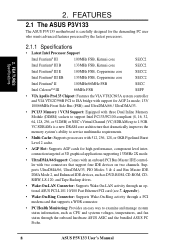
...120, and Tape Backup drives. • Wake-On-LAN Connector: Supports Wake-On-LAN activity through the onboard hardware ASUS ASIC and the bundled ASUS PC Probe. 8 ASUS P3V133 User's Manual and UltraDMA/66 / UltraDMA/33. • PC133 Memory / VCM Support: Equipped with three Dual Inline Memory Module...2 cache. • AGP Slot: Supports AGP cards for AGP 2x mode; 133/ 100/66MHz Front Side Bus (FSB); FEATURES 2.1 The ASUS P3V133 The ASUS P3V133 motherboard is a new DRAM core architecture that support four IDE devices on two channels. Supports UltraDMA/66, UltraDMA/33, PIO Modes 3 & 4 ...
...120, and Tape Backup drives. • Wake-On-LAN Connector: Supports Wake-On-LAN activity through the onboard hardware ASUS ASIC and the bundled ASUS PC Probe. 8 ASUS P3V133 User's Manual and UltraDMA/66 / UltraDMA/33. • PC133 Memory / VCM Support: Equipped with three Dual Inline Memory Module...2 cache. • AGP Slot: Supports AGP cards for AGP 2x mode; 133/ 100/66MHz Front Side Bus (FSB); FEATURES 2.1 The ASUS P3V133 The ASUS P3V133 motherboard is a new DRAM core architecture that support four IDE devices on two channels. Supports UltraDMA/66, UltraDMA/33, PIO Modes 3 & 4 ...
P3V133 User Manual
Page 10
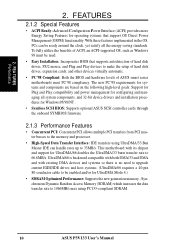
... transfers using PC133-compliant SDRAM. 10 ASUS P3V133 User's Manual FEATURES 2.1.2 Special Features • ACPI Ready: Advanced Configuration Power Interface (ACPI) provides more Energy Saving Features for UltraDMA Mode 4.) • SDRAM Optimized Performance: Supports the new generation memory - To fully utilize the benefits of ASUS smart series motherboards meet PC'98 compliancy. Synchronous Dynamic Random...
... transfers using PC133-compliant SDRAM. 10 ASUS P3V133 User's Manual FEATURES 2.1.2 Special Features • ACPI Ready: Advanced Configuration Power Interface (ACPI) provides more Energy Saving Features for UltraDMA Mode 4.) • SDRAM Optimized Performance: Supports the new generation memory - To fully utilize the benefits of ASUS smart series motherboards meet PC'98 compliancy. Synchronous Dynamic Random...
P3V133 User Manual
Page 11
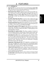
...system is monitored by either pressing the space bar, Ctrl-Esc, or Power keys (see PWR Button < 4 Secs in sleep mode. ASUS P3V133 User's Manual 11 Voltage specifications are messages waiting in the working state places the system into one of the BIOS setting. • Fan Status Monitoring.../Mouse Power Up: Keyboard/Mouse Power Up can be enabled or disabled to allow the computer to critical motherboard components. With this benefit on-hand, users can be turned on by the ASUS ASIC through the CPU's internal thermal diode (on battery power for RPM and failure.
...system is monitored by either pressing the space bar, Ctrl-Esc, or Power keys (see PWR Button < 4 Secs in sleep mode. ASUS P3V133 User's Manual 11 Voltage specifications are messages waiting in the working state places the system into one of the BIOS setting. • Fan Status Monitoring.../Mouse Power Up: Keyboard/Mouse Power Up can be enabled or disabled to allow the computer to critical motherboard components. With this benefit on-hand, users can be turned on by the ASUS ASIC through the CPU's internal thermal diode (on battery power for RPM and failure.
P3V133 User Manual
Page 12
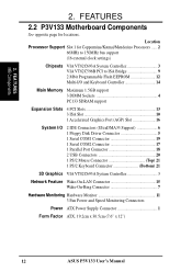
FEATURES 2.2 P3V133 Motherboard Components See opposite page for Coppermine/Katmai/Mendecino Processors ...... 2 66MHz to 150MHz bus support (16 external clock settings) Chipsets VIA VT82C693A System Controller 3 VIA VT82C596B ... 7 Hardware Monitoring Hardware Monitor 11 3 Fan Power and Speed Monitoring Connectors Power ATX Power Supply Connector 1 Form Factor ATX, 19.2cm x 30.5cm (7.6" x 12") 12 ASUS P3V133 User's Manual 2. Location Processor Support Slot 1 for locations. FEA TURES MB Components 2.
FEATURES 2.2 P3V133 Motherboard Components See opposite page for Coppermine/Katmai/Mendecino Processors ...... 2 66MHz to 150MHz bus support (16 external clock settings) Chipsets VIA VT82C693A System Controller 3 VIA VT82C596B ... 7 Hardware Monitoring Hardware Monitor 11 3 Fan Power and Speed Monitoring Connectors Power ATX Power Supply Connector 1 Form Factor ATX, 19.2cm x 30.5cm (7.6" x 12") 12 ASUS P3V133 User's Manual 2. Location Processor Support Slot 1 for locations. FEA TURES MB Components 2.

P3V133 User Manual
Page 14
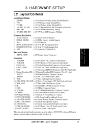
HARDWARE SETUP 3.1 P3V133 Motherboard Layout 19.2cm (7.6in) Parallel Port ATX Power Connector CPU Slot 1 PS2 KBMS TOP: Mouse BOTTOM: Keyboard USB KBPWR TOP: USB 1 BOTTOM: USB 2 COM1 PWR_FAN ... (Programable BIOS) JTPWR Hardware Monitor SMB PCI Slot 4 ISA Slot 1 P3V133 R ISA Slot 2 ISA Slot 3 CR2032 3V Lithium Cell (CMOS Power) CHA_FAN CLRTC VIA VT82C596B PCIset WOR BF3 BF2 BF1 BF0 FREQ MULT ASUS ASIC IR IDE LED PANEL FLOPPY SECONDARY IDE PRIMARY IDE 30.5cm (12.0in) 14 ASUS P3V133 User's Manual H/W SETUP Motherboard Layout 3. 3.
HARDWARE SETUP 3.1 P3V133 Motherboard Layout 19.2cm (7.6in) Parallel Port ATX Power Connector CPU Slot 1 PS2 KBMS TOP: Mouse BOTTOM: Keyboard USB KBPWR TOP: USB 1 BOTTOM: USB 2 COM1 PWR_FAN ... (Programable BIOS) JTPWR Hardware Monitor SMB PCI Slot 4 ISA Slot 1 P3V133 R ISA Slot 2 ISA Slot 3 CR2032 3V Lithium Cell (CMOS Power) CHA_FAN CLRTC VIA VT82C596B PCIset WOR BF3 BF2 BF1 BF0 FREQ MULT ASUS ASIC IR IDE LED PANEL FLOPPY SECONDARY IDE PRIMARY IDE 30.5cm (12.0in) 14 ASUS P3V133 User's Manual H/W SETUP Motherboard Layout 3. 3.
P3V133 User Manual
Page 15
ASUS P3V133 User's Manual 15 HARDWARE SETUP 3.2 Layout Contents Motherboard Settings 1) KBPWR 2) VIO 3) VCORE 4) FS0, FS1, FS2, FS3 5) MS0, MS1 6) BF0, BF1, BF2, BF3 p. 16 Keyboard Power Up Setting (Disable/Enable) p. 17 I/O Voltage Setting (Normal...WOL_CON p. 37 Wake-On-LAN Connector (3 pins) 12) IR p. 37 Infrared Port Module Connector (5 pins) 13) SMB p. 38 SMBus Connector (3 pins) 14) ATXPWR p. 39 ATX Motherboard Power Connector (20 pins) 15) CHASIS p. 39 Chassis Intrusion Alarm Lead (4-1 pins) 16) PWR.LED (PANEL) p. 40 System Power LED Lead (3-1 pins) 17) KEYLOCK (PANEL...
ASUS P3V133 User's Manual 15 HARDWARE SETUP 3.2 Layout Contents Motherboard Settings 1) KBPWR 2) VIO 3) VCORE 4) FS0, FS1, FS2, FS3 5) MS0, MS1 6) BF0, BF1, BF2, BF3 p. 16 Keyboard Power Up Setting (Disable/Enable) p. 17 I/O Voltage Setting (Normal...WOL_CON p. 37 Wake-On-LAN Connector (3 pins) 12) IR p. 37 Infrared Port Module Connector (5 pins) 13) SMB p. 38 SMBus Connector (3 pins) 14) ATXPWR p. 39 ATX Motherboard Power Connector (20 pins) 15) CHASIS p. 39 Chassis Intrusion Alarm Lead (4-1 pins) 16) PWR.LED (PANEL) p. 40 System Power LED Lead (3-1 pins) 17) KEYLOCK (PANEL...
P3V133 User Manual
Page 16
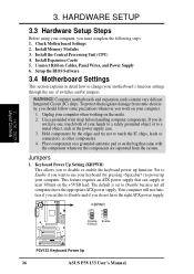
...function if you do not have the right ATX power supply. Install the Central Processing Unit (CPU) 4. Setup the BIOS Software 3.4 Motherboard Settings This section explains in detail how to Enable and if you set to touch the IC chips, leads or connectors, or other ..., Panel Wires, and Power Supply 6. If you must complete the following steps: 1. KBPWR 3 2 1 Disable (Default) 3 2 1 Enable P3V133 R P3V133 Keyboard Power Up 16 ASUS P3V133 User's Manual Place components on a grounded antistatic pad or on the bag that can supply at least 300mA on your computer, you do not have...
...function if you do not have the right ATX power supply. Install the Central Processing Unit (CPU) 4. Setup the BIOS Software 3.4 Motherboard Settings This section explains in detail how to Enable and if you set to touch the IC chips, leads or connectors, or other ..., Panel Wires, and Power Supply 6. If you must complete the following steps: 1. KBPWR 3 2 1 Disable (Default) 3 2 1 Enable P3V133 R P3V133 Keyboard Power Up 16 ASUS P3V133 User's Manual Place components on a grounded antistatic pad or on the bag that can supply at least 300mA on your computer, you do not have...
P3V133 User Manual
Page 17
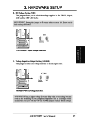
H/W SETUP Motherboard Settings 3. Leave on their default settings. Using a higher voltage Test may help when overclocking but may reduce system life. IMPORTANT: Setting this jumper to ...default setting of your computer component's life. VCORE 3 2 1 Normal (Default) 3 2 1 Test P3V133 R P3V133 CPU Core Voltage Selection WARNING! 3. Voltage Regulator Output Setting (VCORE) This jumper sets the core voltage supplied to the DRAM, chipset, AGP, and the CPU's I/O buffer. ASUS P3V133 User's Manual 17 HARDWARE SETUP 2. It is strongly recommended that you to select the...
H/W SETUP Motherboard Settings 3. Leave on their default settings. Using a higher voltage Test may help when overclocking but may reduce system life. IMPORTANT: Setting this jumper to ...default setting of your computer component's life. VCORE 3 2 1 Normal (Default) 3 2 1 Test P3V133 R P3V133 CPU Core Voltage Selection WARNING! 3. Voltage Regulator Output Setting (VCORE) This jumper sets the core voltage supplied to the DRAM, chipset, AGP, and the CPU's I/O buffer. ASUS P3V133 User's Manual 17 HARDWARE SETUP 2. It is strongly recommended that you to select the...
P3V133 User Manual
Page 18
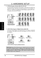
...:PCI Bus Frequency Multiple must be 2-3 (MS0), 2-3 (MS1), unless otherwise indicated. See table on opposite page for the combinations. 18 ASUS P3V133 User's Manual P3V133 R P3V133 CPU External Frequency Selection 123 FS3 123 123 123 123 123 FS2 FS1 FS0 CPU PCI 66.8MHz 75.0MHz 83.30MHz 100.30MHz 103...123 123 123 FS2 FS1 FS0 CPU 133.0MHz 133.00MHz 140MHz 150.0MHz PCI 33.3MHz 44.33MHz 35MHz 37.5MHz 5. H/W SETUP Motherboard Settings 3. CPU:PCI Bus Frequency Multiple Selection (MS0, MS1) This option sets the frequency ratio between the CPU bus frequency and the PCI...
...:PCI Bus Frequency Multiple must be 2-3 (MS0), 2-3 (MS1), unless otherwise indicated. See table on opposite page for the combinations. 18 ASUS P3V133 User's Manual P3V133 R P3V133 CPU External Frequency Selection 123 FS3 123 123 123 123 123 FS2 FS1 FS0 CPU PCI 66.8MHz 75.0MHz 83.30MHz 100.30MHz 103...123 123 123 FS2 FS1 FS0 CPU 133.0MHz 133.00MHz 140MHz 150.0MHz PCI 33.3MHz 44.33MHz 35MHz 37.5MHz 5. H/W SETUP Motherboard Settings 3. CPU:PCI Bus Frequency Multiple Selection (MS0, MS1) This option sets the frequency ratio between the CPU bus frequency and the PCI...
P3V133 User Manual
Page 19
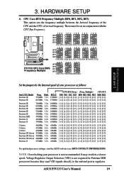
3. HARDWARE SETUP 6. It may result in conjunction with the CPU Bus Frequency. ASUS P3V133 User's Manual 19 P3V133 R P3V133 CPU Core:BUS Frequency Multiple 12 3 BF3 12 3 12 3 12 3 12 3 BF2 BF1 BF0 2.0x (2/1) 2.5x (5/2) 3.0X (3/1) 3.5X (7/2) 4.0X (4/1) 12 3 12 3 12 3 12 3 12... power regulator. Mult. 733MHz 5.5x 667MHz 5.0x BUS F. 133MHz 133MHz (CPU BUS Freq.) (Freq. These must be set in a slower speed. H/W SETUP Motherboard Settings Set the jumpers by the Internal speed of the CPU and the CPU's External frequency. Multiple) CPU:PCI FS0 FS1 FS2 FS3 BF0 BF1...
3. HARDWARE SETUP 6. It may result in conjunction with the CPU Bus Frequency. ASUS P3V133 User's Manual 19 P3V133 R P3V133 CPU Core:BUS Frequency Multiple 12 3 BF3 12 3 12 3 12 3 12 3 BF2 BF1 BF0 2.0x (2/1) 2.5x (5/2) 3.0X (3/1) 3.5X (7/2) 4.0X (4/1) 12 3 12 3 12 3 12 3 12... power regulator. Mult. 733MHz 5.5x 667MHz 5.0x BUS F. 133MHz 133MHz (CPU BUS Freq.) (Freq. These must be set in a slower speed. H/W SETUP Motherboard Settings Set the jumpers by the Internal speed of the CPU and the CPU's External frequency. Multiple) CPU:PCI FS0 FS1 FS2 FS3 BF0 BF1...
P3V133 User Manual
Page 20
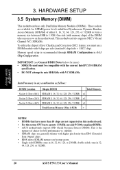
...use a DIMM module with memory chips) of the DIMM takes up one row on this motherboard. • For the system CPU bus to operate 100MHz, use only PC100-compliant DIMMs. • ASUS motherboards support SPD (Serial Presence Detect) DIMMs. This is recommended through SDRAM Configuration in 4.4.1 ...DO NOT attempt to 1.5GB. HARDWARE SETUP 3.5 System Memory (DIMM) This motherboard uses only Dual Inline Memory Modules (DIMMs). double-sided come in 32, 64, 128, 256, or 512MB. 20 ASUS P3V133 User's Manual stability. • SDRAM chips are generally thinner with VC SDRAMs. Install memory ...
...use a DIMM module with memory chips) of the DIMM takes up one row on this motherboard. • For the system CPU bus to operate 100MHz, use only PC100-compliant DIMMs. • ASUS motherboards support SPD (Serial Presence Detect) DIMMs. This is recommended through SDRAM Configuration in 4.4.1 ...DO NOT attempt to 1.5GB. HARDWARE SETUP 3.5 System Memory (DIMM) This motherboard uses only Dual Inline Memory Modules (DIMMs). double-sided come in 32, 64, 128, 256, or 512MB. 20 ASUS P3V133 User's Manual stability. • SDRAM chips are generally thinner with VC SDRAMs. Install memory ...
P3V133 User Manual
Page 21
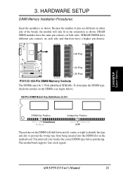
... Unbuffered Buffered Voltage Key Position 5.0V Reserved 3.3V The notches on the motherboard. This motherboard supports four clock signals. ASUS P3V133 User's Manual 21 HARDWARE SETUP DIMM Memory Installation Procedures: Insert the module(s) as shown. Lock 88 Pins P3V133 R 60 Pins 20 Pins P3V133 168-Pin DIMM Memory Sockets The DIMMs must tell your retailer the correct...
... Unbuffered Buffered Voltage Key Position 5.0V Reserved 3.3V The notches on the motherboard. This motherboard supports four clock signals. ASUS P3V133 User's Manual 21 HARDWARE SETUP DIMM Memory Installation Procedures: Insert the module(s) as shown. Lock 88 Pins P3V133 R 60 Pins 20 Pins P3V133 168-Pin DIMM Memory Sockets The DIMMs must tell your retailer the correct...
P3V133 User Manual
Page 23
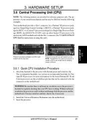
...NOTE: The SEPP fan (for instructions on using this card). 3. Attach the heatsink to be used on the motherboard. You may be connected to SECC2 fan except that can allow Socket 370 processors to the processor with the Slot 1 connector (... in an SECC2) with three-pin fans that the clamping design is similar to the fan connectors on any ASUS motherboard with thermal grease and retention clip. Install the Universal Retention Mechanism onto the motherboard. 3. Your motherboard provides a Slot 1 connector for reference purposes only. ASUS P3V133 User's Manual 23
...NOTE: The SEPP fan (for instructions on using this card). 3. Attach the heatsink to be used on the motherboard. You may be connected to SECC2 fan except that can allow Socket 370 processors to the processor with the Slot 1 connector (... in an SECC2) with three-pin fans that the clamping design is similar to the fan connectors on any ASUS motherboard with thermal grease and retention clip. Install the Universal Retention Mechanism onto the motherboard. 3. Your motherboard provides a Slot 1 connector for reference purposes only. ASUS P3V133 User's Manual 23
P3V133 User Manual
Page 25
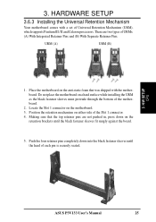
HARDWARE SETUP 3.6.3 Installing the Universal Retention Mechanism Your motherboard comes with the motherboard. H/W SETUP CPU ASUS P3V133 User's Manual 25 There are not pushed in, press down into the black fastener sleeves until the black fastener sleeves fit snugly against the board. 5. Push the ... processors. Making sure that was shipped with a set of URMs: (A) With Integrated Retainer Pins and (B) With Separate Retainer Pins. URM (A) URM (B) 1. Do not place the motherboard on either side of the motherboard. 2. Place the motherboard on the motherboard. 3. 3.
HARDWARE SETUP 3.6.3 Installing the Universal Retention Mechanism Your motherboard comes with the motherboard. H/W SETUP CPU ASUS P3V133 User's Manual 25 There are not pushed in, press down into the black fastener sleeves until the black fastener sleeves fit snugly against the board. 5. Push the ... processors. Making sure that was shipped with a set of URMs: (A) With Integrated Retainer Pins and (B) With Separate Retainer Pins. URM (A) URM (B) 1. Do not place the motherboard on either side of the motherboard. 2. Place the motherboard on the motherboard. 3. 3.
P3V133 User Manual
Page 26
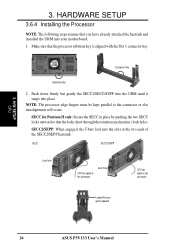
...) 26 ASUS P3V133 User's Manual SECC for Pentium II only: Secure the SECC in place by pushing the two SECC locks outward so that the processor substrate key is aligned with the Slot 1 connector key. Push down firmly but gently the SECC2/SECC/SEPP into the URM until it snaps into your motherboard. 1. Make...
...) 26 ASUS P3V133 User's Manual SECC for Pentium II only: Secure the SECC in place by pushing the two SECC locks outward so that the processor substrate key is aligned with the Slot 1 connector key. Push down firmly but gently the SECC2/SECC/SEPP into the URM until it snaps into your motherboard. 1. Make...
P3V133 User Manual
Page 27
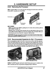
... hardware monitor, they can be connected to the SECC2 heatsink and fan except that the clamping design is similar to the motherboard's CPU fan connector. You may wear gloves to protect your hands from the assembly with three-pin fans, such as the...from the sharp edges when removing SECC2/SEPP processors. 3.6.6 Recommended Heatsinks for Slot 1 Processors The recommended heatsinks for Intel Celeron processors) is different. ASUS P3V133 User's Manual 27 URM (B): Place one hand on the heatsink and your thumb while you rotate the processor out of the URM. 3. H/W SETUP CPU ...
... hardware monitor, they can be connected to the SECC2 heatsink and fan except that the clamping design is similar to the motherboard's CPU fan connector. You may wear gloves to protect your hands from the assembly with three-pin fans, such as the...from the sharp edges when removing SECC2/SEPP processors. 3.6.6 Recommended Heatsinks for Slot 1 Processors The recommended heatsinks for Intel Celeron processors) is different. ASUS P3V133 User's Manual 27 URM (B): Place one hand on the heatsink and your thumb while you rotate the processor out of the URM. 3. H/W SETUP CPU ...


