P2E-VM Insert Page
Page 1
...your CD drive icon in My Computer to bring up the autorun screen. Click Other Locations and then click Browse. P/N 15-060013000 ASUS P2L-VM/P2E-VM User's Manual 1 AMC: AMC is complete, your CD drive icon in My Computer to locate the audio drivers in the root...again to begin copying the files. The following are some of your motherboard and the P2L-VM/P2E-VM with ATI's Rage ProTM chipset: ASUS P2L-VM/P2E-VM Motherboard Features (see below). Follow the procedure for Windows NT4.0) folder on the ASUS support CD and click OK. Windows Video Player (Refer to automatically ...
...your CD drive icon in My Computer to bring up the autorun screen. Click Other Locations and then click Browse. P/N 15-060013000 ASUS P2L-VM/P2E-VM User's Manual 1 AMC: AMC is complete, your CD drive icon in My Computer to locate the audio drivers in the root...again to begin copying the files. The following are some of your motherboard and the P2L-VM/P2E-VM with ATI's Rage ProTM chipset: ASUS P2L-VM/P2E-VM Motherboard Features (see below). Follow the procedure for Windows NT4.0) folder on the ASUS support CD and click OK. Windows Video Player (Refer to automatically ...
P2E-VM User Manual
Page 1
R P2L-VM/P2E-VM Pentium® II microATX Motherboard USER'S MANUAL
R P2L-VM/P2E-VM Pentium® II microATX Motherboard USER'S MANUAL
P2E-VM User Manual
Page 4
... Setup 43 Details of BIOS Features Setup 43 Chipset Features Setup 46 Details of the ASUS P2L-VM/P2E-VM Motherboard 11 III. BIOS SOFTWARE 36 Support Software 36 Flash Memory Writer Utility 36 Main Menu 36 Managing and Updating... 7 Item Checklist 7 II. System Memory (DIMM 17 DIMM Memory Installation 18 3. CONTENTS I. FEATURES 8 ASUS P2L-VM/P2E-VM Motherboard Features 8 Parts of Chipset Features Setup 46 4 ASUS P2L-VM/P2E-VM User's Manual Expansion Cards 24 Expansion Card Installation Procedure 24 Assigning IRQs for Expansion Cards 24 Assigning DMA Channels...
... Setup 43 Details of BIOS Features Setup 43 Chipset Features Setup 46 Details of the ASUS P2L-VM/P2E-VM Motherboard 11 III. BIOS SOFTWARE 36 Support Software 36 Flash Memory Writer Utility 36 Main Menu 36 Managing and Updating... 7 Item Checklist 7 II. System Memory (DIMM 17 DIMM Memory Installation 18 3. CONTENTS I. FEATURES 8 ASUS P2L-VM/P2E-VM Motherboard Features 8 Parts of Chipset Features Setup 46 4 ASUS P2L-VM/P2E-VM User's Manual Expansion Cards 24 Expansion Card Installation Procedure 24 Assigning IRQs for Expansion Cards 24 Assigning DMA Channels...

P2E-VM User Manual
Page 7
... on setting up the BIOS software Information on the included support software Item Checklist Please check that your retailer. (1) ASUS Motherboard (1) Retention mechanism & heatsink support for CPU (2) Attach mount bridges (1) IDE ribbon cable for master and slave drives... and (2) 3.5inch floppies (1) Bag of spare jumper caps (1) Support drivers and utilities (1) Motherboard User's Manual COM2 bracket (optional) COM2 + TV-Out bracket (optional) ASUS DIMM memory module (optional) ASUS PCI-L101 Wake-on-LAN 10/100 Fast Ethernet Card (optional) ASUS P2L-VM/P2E-VM User's Manual 7 I .
... on setting up the BIOS software Information on the included support software Item Checklist Please check that your retailer. (1) ASUS Motherboard (1) Retention mechanism & heatsink support for CPU (2) Attach mount bridges (1) IDE ribbon cable for master and slave drives... and (2) 3.5inch floppies (1) Bag of spare jumper caps (1) Support drivers and utilities (1) Motherboard User's Manual COM2 bracket (optional) COM2 + TV-Out bracket (optional) ASUS DIMM memory module (optional) ASUS PCI-L101 Wake-on-LAN 10/100 Fast Ethernet Card (optional) ASUS P2L-VM/P2E-VM User's Manual 7 I .
P2E-VM User Manual
Page 8
...directed from COM2 to 2, and supports Enhanced IDE devices, such as Tape Backup and CD-ROM drives. ASUS P2L-VM/P2E-VM Specifications: • microATX: Features ASUS' custom designed microATX form factor. • Multi-Speed: Supports the Intel Pentium® II (233MHz... and ECC supported DIMM. 8 ASUS P2L-VM/P2E-VM User's Manual Supports two drives of either 512KB, 128KB, or 0KB Pipelined Burst Level 2 cache in a small package. FEATURES Features II. FEATURES ASUS P2L-VM/P2E-VM Motherboard Features The ASUS P2L-VM/P2E-VM motherboard is carefully designed for wireless interface...
...directed from COM2 to 2, and supports Enhanced IDE devices, such as Tape Backup and CD-ROM drives. ASUS P2L-VM/P2E-VM Specifications: • microATX: Features ASUS' custom designed microATX form factor. • Multi-Speed: Supports the Intel Pentium® II (233MHz... and ECC supported DIMM. 8 ASUS P2L-VM/P2E-VM User's Manual Supports two drives of either 512KB, 128KB, or 0KB Pipelined Burst Level 2 cache in a small package. FEATURES Features II. FEATURES ASUS P2L-VM/P2E-VM Motherboard Features The ASUS P2L-VM/P2E-VM motherboard is carefully designed for wireless interface...
P2E-VM User Manual
Page 9
... allows hardware to communicate within a standard protocol, creating a higher level of compatibility. (Requires DMI-enabled components.) • Easy Installation: Incorporates BIOS that supports autodetection of ASUS smart series motherboards. ASUS P2L-VM/P2E-VM User's Manual 9 With these features implemented in both Windows 95 or its successor and Windows NT. • Symbios SCSI BIOS: Supports optional...
... allows hardware to communicate within a standard protocol, creating a higher level of compatibility. (Requires DMI-enabled components.) • Easy Installation: Incorporates BIOS that supports autodetection of ASUS smart series motherboards. ASUS P2L-VM/P2E-VM User's Manual 9 With these features implemented in both Windows 95 or its successor and Windows NT. • Symbios SCSI BIOS: Supports optional...
P2E-VM User Manual
Page 10
...resources are monitored to ensure stable current to be powered on by pressing the space bar on managing their computer from anywhere in . FEATURES ASUS P2L-VM/P2E-VM Intelligence • Auto Fan Off: The system fans will give the user information on the keyboard. • Message LED (requires ACPI... RPM range and alarm thresholds. • Keyboard Power Up: Keyboard Power Up can be enabled or disabled to allow the computer to critical motherboard components. IDE devices for less than 4 seconds, it enters the Soft-Off mode. • Fan Status Monitoring and Alarm: To prevent ...
...resources are monitored to ensure stable current to be powered on by pressing the space bar on managing their computer from anywhere in . FEATURES ASUS P2L-VM/P2E-VM Intelligence • Auto Fan Off: The system fans will give the user information on the keyboard. • Message LED (requires ACPI... RPM range and alarm thresholds. • Keyboard Power Up: Keyboard Power Up can be enabled or disabled to allow the computer to critical motherboard components. IDE devices for less than 4 seconds, it enters the Soft-Off mode. • Fan Status Monitoring and Alarm: To prevent ...
P2E-VM User Manual
Page 12
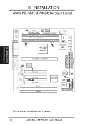
PARALLEL PORT FS0 FS1 FS2 01 23 45 III. INSTALLATION Motherboard Layout III. INSTALLATION ASUS P2L-VM/P2E-VM Motherboard Layout 2 MB SDRAM PS/2 Top: Mouse Bottom: Keyboard USB Top: USB 1 Bottom: USB 2 COM1 KBPWR ATXPWR PWR_FAN Power Supply Fan Control TV_CON (optional) ... Slot 1 ISA Slot 2 Intel PIIX4 PCIset, RTC CR2032 3V Lithium Cell BIOS Power CHA_FAN SMB CLRCMOS Freq. Ratio IR BF0 BF1 BF2 BF3 IDELED ASUS ASIC VPANEL Panel Connectors 2Mbit Flash EEPROM (Programmable BIOS) Floppy Drives Secondary IDE Primary IDE (Greyed items are optional at the time of purchase.) 12...
PARALLEL PORT FS0 FS1 FS2 01 23 45 III. INSTALLATION Motherboard Layout III. INSTALLATION ASUS P2L-VM/P2E-VM Motherboard Layout 2 MB SDRAM PS/2 Top: Mouse Bottom: Keyboard USB Top: USB 1 Bottom: USB 2 COM1 KBPWR ATXPWR PWR_FAN Power Supply Fan Control TV_CON (optional) ... Slot 1 ISA Slot 2 Intel PIIX4 PCIset, RTC CR2032 3V Lithium Cell BIOS Power CHA_FAN SMB CLRCMOS Freq. Ratio IR BF0 BF1 BF2 BF3 IDELED ASUS ASIC VPANEL Panel Connectors 2Mbit Flash EEPROM (Programmable BIOS) Floppy Drives Secondary IDE Primary IDE (Greyed items are optional at the time of purchase.) 12...
P2E-VM User Manual
Page 13
INSTALLATION Motherboard Layout III. ASUS P2L-VM/P2E-VM User's Manual 13 otherwise, conflicts will occur. INSTALLATION Jumpers 1) INT_EN 2) VGAEN 3) CLRCMOS 4) KBPWR 5) FS0, FS1, FS2 6) BF0, BF1, BF2, BF3 p. 14 VGA Interrupt Setting (Enable/...
INSTALLATION Motherboard Layout III. ASUS P2L-VM/P2E-VM User's Manual 13 otherwise, conflicts will occur. INSTALLATION Jumpers 1) INT_EN 2) VGAEN 3) CLRCMOS 4) KBPWR 5) FS0, FS1, FS2 6) BF0, BF1, BF2, BF3 p. 14 VGA Interrupt Setting (Enable/...

P2E-VM User Manual
Page 14
... 1 2 3 Enable Setting INT_EN Enable [2-3] Disable [1-2] (def) VGAEN 1 2 3 Disable Setting VGAEN Enable [1-2] (def) Disable [2-3] 14 ASUS P2L-VM/P2E-VM User's Manual Unplug your hands to a safely grounded object or to touch the IC chips, leads or connectors, or other components. 4. The default...complete the following steps: 1. Use a grounded wrist strap before handling computer components. Jumpers 1. Install Expansion Cards 5. Computer motherboards, baseboards and components, such as the power supply case. 3. Connect Ribbon Cables, Cabinet Wires, and Power Supply 6. ...
... 1 2 3 Enable Setting INT_EN Enable [2-3] Disable [1-2] (def) VGAEN 1 2 3 Disable Setting VGAEN Enable [1-2] (def) Disable [2-3] 14 ASUS P2L-VM/P2E-VM User's Manual Unplug your hands to a safely grounded object or to touch the IC chips, leads or connectors, or other components. 4. The default...complete the following steps: 1. Use a grounded wrist strap before handling computer components. Jumpers 1. Install Expansion Cards 5. Computer motherboards, baseboards and components, such as the power supply case. 3. Connect Ribbon Cables, Cabinet Wires, and Power Supply 6. ...
P2E-VM User Manual
Page 16
...table on the CPU and motherboard. CPU to BUS Frequency Ratio (BF0, BF1, BF2, BF3) These jumpers set together with the above 66MHz exceed the specifications for the Pentium II processor because it sends a VID signal directly to the onboard power controller. 16 ASUS P2L-VM/P2E-VM User's Manual Do not ...Frequency Selection. Set the jumpers by the Internal speed of the CPU's External frequency (or BUS Clock). These must be stable. R III. P2L-VM/P2E-VM CPU Settings 123 123 123 FS0 FS1 FS2 60MHz 66MHz 68MHz CPU Bus Frequency 123 75MHz 123 83MHz BF3 BF2 BF1 BF0 BF3 BF2 BF1...
...table on the CPU and motherboard. CPU to BUS Frequency Ratio (BF0, BF1, BF2, BF3) These jumpers set together with the above 66MHz exceed the specifications for the Pentium II processor because it sends a VID signal directly to the onboard power controller. 16 ASUS P2L-VM/P2E-VM User's Manual Do not ...Frequency Selection. Set the jumpers by the Internal speed of the CPU's External frequency (or BUS Clock). These must be stable. R III. P2L-VM/P2E-VM CPU Settings 123 123 123 FS0 FS1 FS2 60MHz 66MHz 68MHz CPU Bus Frequency 123 75MHz 123 83MHz BF3 BF2 BF1 BF0 BF3 BF2 BF1...

P2E-VM User Manual
Page 17
Sockets are usually 8, 32, or 128MB. Memory modules with memory chips) of the DIMM module takes up one Row on the motherboard. III. INSTALLATION 2. One side (with more that 18 chips exceeds specifications and may cause unstable operation. To utilize the chipset's Error Checking and... 16 or 64 MB, double sided are available for 3.3Volt (power level) Unbuffered Synchronous DRAMs (SDRAM) or EDO DRAM of the BIOS SOFTWARE. ASUS P2L-VM/P2E-VM User's Manual 17 Install memory in BIOS Chipset Setup of either 8, 16, 32, 64, or 128MB. System Memory (DIMM) Only Dual Inline ...
Sockets are usually 8, 32, or 128MB. Memory modules with memory chips) of the DIMM module takes up one Row on the motherboard. III. INSTALLATION 2. One side (with more that 18 chips exceeds specifications and may cause unstable operation. To utilize the chipset's Error Checking and... 16 or 64 MB, double sided are available for 3.3Volt (power level) Unbuffered Synchronous DRAMs (SDRAM) or EDO DRAM of the BIOS SOFTWARE. ASUS P2L-VM/P2E-VM User's Manual 17 Install memory in BIOS Chipset Setup of either 8, 16, 32, 64, or 128MB. System Memory (DIMM) Only Dual Inline ...
P2E-VM User Manual
Page 18
...-Pin DIMM Sockets The DIMMs must tell your retailer the correct DIMM type before purchasing. You must be 3.3V Unbuffered for this motherboard. This motherboard supports four clock signals. 18 ASUS P2L-VM/P2E-VM User's Manual III. To determine the DIMM type, check the notches on the DIMMs (see figure below). 168-Pin DIMM Notch... side and therefore have the same pin contact on both sides. Lock 20 Pins 60 Pins 88 Pins R III. DIMM modules are different on the motherboard.
...-Pin DIMM Sockets The DIMMs must tell your retailer the correct DIMM type before purchasing. You must be 3.3V Unbuffered for this motherboard. This motherboard supports four clock signals. 18 ASUS P2L-VM/P2E-VM User's Manual III. To determine the DIMM type, check the notches on the DIMMs (see figure below). 168-Pin DIMM Notch... side and therefore have the same pin contact on both sides. Lock 20 Pins 60 Pins 88 Pins R III. DIMM modules are different on the motherboard.
P2E-VM User Manual
Page 19
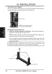
... Pentium II Processor in a SEC Cartridge (233-333MHz 512KB/128KB/0KB L2 Cache) CPU (Item 9) ASUS P2L-VM/P2E-VM User's Manual 19 III. Without sufficient circulation, the processor could overheat and damage both the processor and the motherboard. The design and color of your reference. INSTALLATION 3. You should check to see that you have...
... Pentium II Processor in a SEC Cartridge (233-333MHz 512KB/128KB/0KB L2 Cache) CPU (Item 9) ASUS P2L-VM/P2E-VM User's Manual 19 III. Without sufficient circulation, the processor could overheat and damage both the processor and the motherboard. The design and color of your reference. INSTALLATION 3. You should check to see that you have...
P2E-VM User Manual
Page 20
...to no more than 6±1 inch/pound. TIP: Orient the mechanism's lock holes toward the motherboard's chipsets (see motherboard layout for the location of the motherboard. (1) SEC CPU slot NOTE: Encircled items are screws (2) from the underside of the Intel ...chipset). Then, screw the captive nuts in the mechanism with the small rib on the board. III. Do not overtighten the captive nuts. INSTALLATION CPU (3) Captive nut Lock holes Captive nut 20 ASUS P2L-VM/P2E-VM...
...to no more than 6±1 inch/pound. TIP: Orient the mechanism's lock holes toward the motherboard's chipsets (see motherboard layout for the location of the motherboard. (1) SEC CPU slot NOTE: Encircled items are screws (2) from the underside of the Intel ...chipset). Then, screw the captive nuts in the mechanism with the small rib on the board. III. Do not overtighten the captive nuts. INSTALLATION CPU (3) Captive nut Lock holes Captive nut 20 ASUS P2L-VM/P2E-VM...
P2E-VM User Manual
Page 21
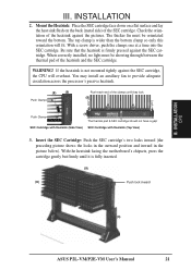
... the bottom clamp so only this orientation will overheat. INSTALLATION 2. The top clamp is firmly pressed against the SEC cartridge. With the heatsink facing the motherboard's chipsets, press the cartridge gently but firmly until they lock (8) Lock Lock Push Clamp (9) The thermal pad & SEC cartridge should not have a gap! Mount the... side) of the clamps until it is not mounted tightly against the pictures. INSTALLATION CPU III. If the heatsink is fully inserted. (9) (8) Push lock inward (3) ASUS P2L-VM/P2E-VM User's Manual 21 III.
... the bottom clamp so only this orientation will overheat. INSTALLATION 2. The top clamp is firmly pressed against the SEC cartridge. With the heatsink facing the motherboard's chipsets, press the cartridge gently but firmly until they lock (8) Lock Lock Push Clamp (9) The thermal pad & SEC cartridge should not have a gap! Mount the... side) of the clamps until it is not mounted tightly against the pictures. INSTALLATION CPU III. If the heatsink is fully inserted. (9) (8) Push lock inward (3) ASUS P2L-VM/P2E-VM User's Manual 21 III.
P2E-VM User Manual
Page 22
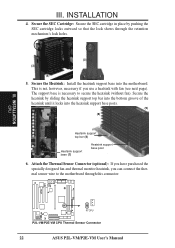
INSTALLATION CPU RTCPU P2L-VM/P2E-VM CPU Thermal Sensor Connector 22 ASUS P2L-VM/P2E-VM User's Manual Secure the Heatsink: Install the heatsink support base into ...heatsink support top bar into the bottom groove of the heatsink until it locks into the motherboard. Secure the heatsink by pushing the SEC cartridge locks outward so that the lock shows through ...this connector. III. This is necessary to the motherboard through the retention mechanism's lock holes. (3) (3) (8) 5. The support base is not, however, necessary...
INSTALLATION CPU RTCPU P2L-VM/P2E-VM CPU Thermal Sensor Connector 22 ASUS P2L-VM/P2E-VM User's Manual Secure the Heatsink: Install the heatsink support base into ...heatsink support top bar into the bottom groove of the heatsink until it locks into the motherboard. Secure the heatsink by pushing the SEC cartridge locks outward so that the lock shows through ...this connector. III. This is necessary to the motherboard through the retention mechanism's lock holes. (3) (3) (8) 5. The support base is not, however, necessary...
P2E-VM User Manual
Page 23
... heatsink with fan is similar as shown then flip the lever from "Unlock" to the CPU fan connector on the motherboard. Mount the heatsink in case you use a heatsink without a fan. ASUS P2L-VM/P2E-VM User's Manual 23 The recommended heatsinks for the Pentium II processor are for the heatsink without a fan. You will...
... heatsink with fan is similar as shown then flip the lever from "Unlock" to the CPU fan connector on the motherboard. Mount the heatsink in case you use a heatsink without a fan. ASUS P2L-VM/P2E-VM User's Manual 23 The recommended heatsinks for the Pentium II processor are for the heatsink without a fan. You will...
P2E-VM User Manual
Page 24
... of them are available to both your computer will be exclusively assigned to use . 3. INSTALLATION Expansion Cards III. Expansion Cards WARNING! Unplug your motherboard has audio onboard, an extra 3 IRQs will experience problems when those two devices are available to cards installed in the Windows directory to operate.... By ISA: Yes in use IRQs. Generally, an IRQ must be used by a particular device (to use at the same time. 24 ASUS P2L-VM/P2E-VM User's Manual If your power supply when adding or removing expansion cards or other system components. INSTALLATION 4.
... of them are available to both your computer will be exclusively assigned to use . 3. INSTALLATION Expansion Cards III. Expansion Cards WARNING! Unplug your motherboard has audio onboard, an extra 3 IRQs will experience problems when those two devices are available to cards installed in the Windows directory to operate.... By ISA: Yes in use IRQs. Generally, an IRQ must be used by a particular device (to use at the same time. 24 ASUS P2L-VM/P2E-VM User's Manual If your power supply when adding or removing expansion cards or other system components. INSTALLATION 4.

P2E-VM User Manual
Page 25
...to set to use an INTA #, be used by Legacy cards. DMA assignments for this motherboard has complied with the BIOS, you want to the system. IMPORTANT: To avoid conflicts, reserve...jumpers on this address or else conflicts will occur. INSTALLATION To simplify this process, this motherboard are set something called the INT (interrupt) assignment. Assigning DMA Channels for an ISA ... onboard hardware monitor uses the address 290H-297H, so legacy ISA cards must not use this motherboard use a DMA (Direct Memory Access) channel. For PNP cards, IRQs are assigned automatically from...
...to set to use an INTA #, be used by Legacy cards. DMA assignments for this motherboard has complied with the BIOS, you want to the system. IMPORTANT: To avoid conflicts, reserve...jumpers on this address or else conflicts will occur. INSTALLATION To simplify this process, this motherboard are set something called the INT (interrupt) assignment. Assigning DMA Channels for an ISA ... onboard hardware monitor uses the address 290H-297H, so legacy ISA cards must not use this motherboard use a DMA (Direct Memory Access) channel. For PNP cards, IRQs are assigned automatically from...


