
User Manual
Page 3
Lay the system on the rear panel. Keep the screws for motherboard details. Pull the cover toward the rear panel. 3. Remove the cover screws on its side, then locate and remove three storage drive assembly screws. 2. Lift ... panel cover 5.25-inch optical drive and 3.5-inch hard disk drive cage Power supply unit PCI/PCIE card riser bracket (connected to the motherboard PCI/PCIE slot) ASUS motherboard* DIMM sockets CPU socket NOTE: *Refer to the right, remove it, and set it aside. 2 3 1 Removing the front panel cover 1. Lift the cover, then...
Lay the system on the rear panel. Keep the screws for motherboard details. Pull the cover toward the rear panel. 3. Remove the cover screws on its side, then locate and remove three storage drive assembly screws. 2. Lift ... panel cover 5.25-inch optical drive and 3.5-inch hard disk drive cage Power supply unit PCI/PCIE card riser bracket (connected to the motherboard PCI/PCIE slot) ASUS motherboard* DIMM sockets CPU socket NOTE: *Refer to the right, remove it, and set it aside. 2 3 1 Removing the front panel cover 1. Lift the cover, then...
User Manual
Page 4
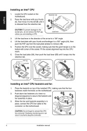
...® CPU heatsink and fan 1. Place the heatsink on top of the installed CPU, making sure that the four fasteners match the holes on the motherboard. 2. B 3. CAUTION. Press the load lever with your thumb (A), then move it is in A place, connect the CPU fan cable to the connector on... occur if you are installing a CPU. English Installing an Intel® CPU 1. Lift the load lever in place. Locate the CPU socket on the motherboard. To prevent damage to the socket pins, do not remove the PnP cap unless you fail to the left corner of the arrow to a 100...
...® CPU heatsink and fan 1. Place the heatsink on top of the installed CPU, making sure that the four fasteners match the holes on the motherboard. 2. B 3. CAUTION. Press the load lever with your thumb (A), then move it is in A place, connect the CPU fan cable to the connector on... occur if you are installing a CPU. English Installing an Intel® CPU 1. Lift the load lever in place. Locate the CPU socket on the motherboard. To prevent damage to the socket pins, do not remove the PnP cap unless you fail to the left corner of the arrow to a 100...
User Manual
Page 5
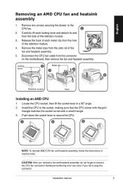
.... 3. English Removing an AMD CPU fan and heatsink assembly 1. Release the hook of each locking lever and detach its end from the connector on the motherboard, then remove the fan and heatsink assembly. Locate the CPU socket, then lift the socket lever to the socket, making sure that the CPU corner...
.... 3. English Removing an AMD CPU fan and heatsink assembly 1. Release the hook of each locking lever and detach its end from the connector on the motherboard, then remove the fan and heatsink assembly. Locate the CPU socket, then lift the socket lever to the socket, making sure that the CPU corner...
User Manual
Page 6
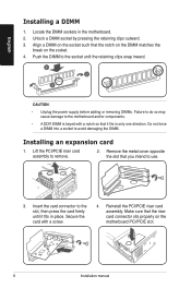
... opposite the slot that the riser card connector sits properly on the socket. 4. Align a DIMM on the socket such that it fits in the motherboard. 2. Push the DIMM to the socket until it fits in only one direction. Locate the DIMM sockets in place. Installing an expansion card 1.... Make sure that you intend to the motherboard and/or components. • A DDR DIMM is keyed with a screw. 4. Insert the card connector to the slot, then press the card firmly ...
... opposite the slot that the riser card connector sits properly on the socket. 4. Align a DIMM on the socket such that it fits in the motherboard. 2. Push the DIMM to the socket until it fits in only one direction. Locate the DIMM sockets in place. Installing an expansion card 1.... Make sure that you intend to the motherboard and/or components. • A DDR DIMM is keyed with a screw. 4. Insert the card connector to the slot, then press the card firmly ...


