P2-99 User Manual
Page 1
® P2-99 Pentium® III / II / CeleronTM Motherboard USER'S MANUAL
® P2-99 Pentium® III / II / CeleronTM Motherboard USER'S MANUAL
P2-99 User Manual
Page 4
CONTENTS I. FEATURES 8 Features of BIOS Features Setup 45 4 ASUS P2-99 User's Manual System Memory (DIMM 18 DIMM Memory Installation Procedures 19 3. BIOS Setup 41 Load Defaults 42 Standard CMOS Setup 42 Details of Standard CMOS Setup 42 BIOS Features Setup 45 Details of the ASUS P2-99 Motherboard 8 The ASUS P2-99 Motherboard 11 III. Motherboard Settings 14 Jumpers 14 2. Central Processing Unit...
CONTENTS I. FEATURES 8 Features of BIOS Features Setup 45 4 ASUS P2-99 User's Manual System Memory (DIMM 18 DIMM Memory Installation Procedures 19 3. BIOS Setup 41 Load Defaults 42 Standard CMOS Setup 42 Details of Standard CMOS Setup 42 BIOS Features Setup 45 Details of the ASUS P2-99 Motherboard 8 The ASUS P2-99 Motherboard 11 III. Motherboard Settings 14 Jumpers 14 2. Central Processing Unit...
P2-99 User Manual
Page 7
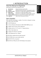
... (2) 3.5" floppy disk drives (1) Bag of spare jumper caps (1) Support CD with drivers and utilities (1) This Motherboard User's Manual ASUS IrDA-compliant infrared module (optional) ASUS CIDB chassis sensor module (optional) ASUS S370 CPU card (optional) ASUS PCI-L101 Wake-On-LAN 10/100 Ethernet Card (optional) ASUS P2-99 User's Manual 7 Hardware Setup Instructions on setting up the BIOS software V.
... (2) 3.5" floppy disk drives (1) Bag of spare jumper caps (1) Support CD with drivers and utilities (1) This Motherboard User's Manual ASUS IrDA-compliant infrared module (optional) ASUS CIDB chassis sensor module (optional) ASUS S370 CPU card (optional) ASUS PCI-L101 Wake-On-LAN 10/100 Ethernet Card (optional) ASUS P2-99 User's Manual 7 Hardware Setup Instructions on setting up the BIOS software V.
P2-99 User Manual
Page 8
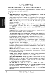
FEATURES Features of the ASUS P2-99 Motherboard The ASUS P2-99 is carefully designed for the demanding PC user who wants advanced features processed by Intel or PC Probe from ASUS. • AGP Slot: Supports an Accelerated Graphics Port card for high performance, component level interconnect targeted at 3D ... to examine and manage system status information such as Tape Backup and CD-ROM, CD-R, CD-RW, and LS-120 drives. 8 ASUS P2-99 User's Manual II. UART2 can also be directed from sleep or soft-off mode. • Thermal Sensor Connector w/Optional Sensor (only w/hardware monitor...
FEATURES Features of the ASUS P2-99 Motherboard The ASUS P2-99 is carefully designed for the demanding PC user who wants advanced features processed by Intel or PC Probe from ASUS. • AGP Slot: Supports an Accelerated Graphics Port card for high performance, component level interconnect targeted at 3D ... to examine and manage system status information such as Tape Backup and CD-ROM, CD-R, CD-RW, and LS-120 drives. 8 ASUS P2-99 User's Manual II. UART2 can also be directed from sleep or soft-off mode. • Thermal Sensor Connector w/Optional Sensor (only w/hardware monitor...
P2-99 User Manual
Page 9
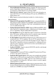
... setup of hard disk drives, expansion cards, and other devices virtually automatic. • PC'98 Compliant: Both the BIOS and hardware levels of ASUS smart series of motherboards meet PC'98 compliancy. fering enhanced ACPI for configuring and managing all is that supports autodetection of hard disk drives, PS/2 mouse, and Plug... through BIOS, which can handle data transfer up to communicate within a standard protocol creating a higher level of most devices for a wireless interface. The best of - ASUS P2-99 User's Manual 9 II. FEA TURES Specifications II.
... setup of hard disk drives, expansion cards, and other devices virtually automatic. • PC'98 Compliant: Both the BIOS and hardware levels of ASUS smart series of motherboards meet PC'98 compliancy. fering enhanced ACPI for configuring and managing all is that supports autodetection of hard disk drives, PS/2 mouse, and Plug... through BIOS, which can handle data transfer up to communicate within a standard protocol creating a higher level of most devices for a wireless interface. The best of - ASUS P2-99 User's Manual 9 II. FEA TURES Specifications II.
P2-99 User Manual
Page 10
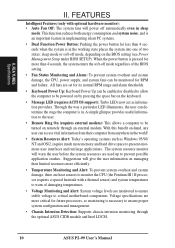
... fans will power off automatically even in . Voltage specifications are used up to critical motherboard components. The system resource monitor will give the user information on remotely through the optional ASUS CIDB module and Intel LDCM. 10 ASUS P2-99 User's Manual All fans are monitored to ensure stable voltage to prevent possible application crashes. This...
... fans will power off automatically even in . Voltage specifications are used up to critical motherboard components. The system resource monitor will give the user information on remotely through the optional ASUS CIDB module and Intel LDCM. 10 ASUS P2-99 User's Manual All fans are monitored to ensure stable voltage to prevent possible application crashes. This...
P2-99 User Manual
Page 11
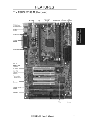
FEATURES The ASUS P2-99 Motherboard T: PS/2 Mouse B: PS/2 Keyboard T: USB1 B: USB2 Serial COM1 T: Parallel B:Serial ATX Power Slot 1 Intel 440ZX AGPset Floppy IDE 2 DIMM Slots Connector Connectors Serial COM2 II. II. FEA TURES Motherboard Parts AGP Port Wake-On-LAN Connector 4 PCI Slots Multi-I/O & Keyboard Controller Programmable Flash EEPROM SB-Link™ Connector Hardware Monitor (optional) 3 ISA Slots Intel PIIX4E PCIset Wake-On-Ring Connector ASUS P2-99 User's Manual 11
FEATURES The ASUS P2-99 Motherboard T: PS/2 Mouse B: PS/2 Keyboard T: USB1 B: USB2 Serial COM1 T: Parallel B:Serial ATX Power Slot 1 Intel 440ZX AGPset Floppy IDE 2 DIMM Slots Connector Connectors Serial COM2 II. II. FEA TURES Motherboard Parts AGP Port Wake-On-LAN Connector 4 PCI Slots Multi-I/O & Keyboard Controller Programmable Flash EEPROM SB-Link™ Connector Hardware Monitor (optional) 3 ISA Slots Intel PIIX4E PCIset Wake-On-Ring Connector ASUS P2-99 User's Manual 11
P2-99 User Manual
Page 12
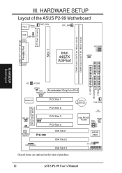
.... 12 ASUS P2-99 User's Manual H/W SETUP Board Layout VIO VCORE FLOPPY SECONDARY IDE PRIMARY IDE JTCPU (WOL) Accelerated Graphics Port Wake-On-LAN Connector Multi-I/O PCI Slot 1 PCI Slot 2 2Mb Flash EEPROM (Programable BIOS) SBLINK CHASIS PCI Slot 3 JTPWR Hardware Monitor PCI Slot 4 P2-99 ISA Slot... (CMOS Power) CHA_FAN CLRTC Intel PIIX4E PCIset WOR BUS FREQ BF3 BF2 BF1 BF0 ASUS ASIC IR IDE LED Panel Connectors Grayed items are optional at the time of the ASUS P2-99 Motherboard T: Mouse PS/2 B: Keyboard PWR_FAN CPU_FAN Parallel Port ATX Power Connector Slot 1 USB...
.... 12 ASUS P2-99 User's Manual H/W SETUP Board Layout VIO VCORE FLOPPY SECONDARY IDE PRIMARY IDE JTCPU (WOL) Accelerated Graphics Port Wake-On-LAN Connector Multi-I/O PCI Slot 1 PCI Slot 2 2Mb Flash EEPROM (Programable BIOS) SBLINK CHASIS PCI Slot 3 JTPWR Hardware Monitor PCI Slot 4 P2-99 ISA Slot... (CMOS Power) CHA_FAN CLRTC Intel PIIX4E PCIset WOR BUS FREQ BF3 BF2 BF1 BF0 ASUS ASIC IR IDE LED Panel Connectors Grayed items are optional at the time of the ASUS P2-99 Motherboard T: Mouse PS/2 B: Keyboard PWR_FAN CPU_FAN Parallel Port ATX Power Connector Slot 1 USB...
P2-99 User Manual
Page 13
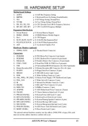
H/W SETUP Layout Contents III. HARDWARE SETUP Motherboard Settings 1) AGPFS 2) KBPWR 3) VIO 4) VCORE 5) FS0, FS1, FS2, FS3 6) BF0, BF1, BF2, BF3 p. 14 AGP Bus Frequency Setting p. 15 Keyboard Power Up Setting (Disable/Enable) p. ...) 12) IR p. 33 Infrared Port Module Connector (5 pins) 13) SBLINK p. 34 SB-Link™ Port Connector (6-1 pins) 14) SMB CON. ASUS P2-99 User's Manual 13 p. 34 SMBus Connector (3 pins) 15) ATXPWR p. 35 ATX Motherboard Power Connector (20 pins) 16) CHASIS p. 35 Chassis Intrusion Alarm Lead (4-1 pins) 17) PWR.LED (PANEL) 18) KEYLOCK (PANEL) 19...
H/W SETUP Layout Contents III. HARDWARE SETUP Motherboard Settings 1) AGPFS 2) KBPWR 3) VIO 4) VCORE 5) FS0, FS1, FS2, FS3 6) BF0, BF1, BF2, BF3 p. 14 AGP Bus Frequency Setting p. 15 Keyboard Power Up Setting (Disable/Enable) p. ...) 12) IR p. 33 Infrared Port Module Connector (5 pins) 13) SBLINK p. 34 SB-Link™ Port Connector (6-1 pins) 14) SMB CON. ASUS P2-99 User's Manual 13 p. 34 SMBus Connector (3 pins) 15) ATXPWR p. 35 ATX Motherboard Power Connector (20 pins) 16) CHASIS p. 35 Chassis Intrusion Alarm Lead (4-1 pins) 17) PWR.LED (PANEL) 18) KEYLOCK (PANEL) 19...

P2-99 User Manual
Page 14
... grounded object or to be stable. 14 ASUS P2-99 User's Manual HARDWARE SETUP Hardware Setup Steps Before using your computer, you work on your computer. 1. Motherboard Settings This section explains in detail how to change your motherboard's function settings through the use of your ... AGPFS 123 AGP Frequency = 2/3 CPU Bus or Host Frequency (Default) (2:3) 123 AGP Frequency = CPU Bus or Host Frequency (1:1) P2-99 P2-99 AGP Frequency Setting WARNING! Jumpers 1. III. AGP bus frequencies above 66MHz exceed the specifications for the AGP interface and are separated from static...
... grounded object or to be stable. 14 ASUS P2-99 User's Manual HARDWARE SETUP Hardware Setup Steps Before using your computer, you work on your computer. 1. Motherboard Settings This section explains in detail how to change your motherboard's function settings through the use of your ... AGPFS 123 AGP Frequency = 2/3 CPU Bus or Host Frequency (Default) (2:3) 123 AGP Frequency = CPU Bus or Host Frequency (1:1) P2-99 P2-99 AGP Frequency Setting WARNING! Jumpers 1. III. AGP bus frequencies above 66MHz exceed the specifications for the AGP interface and are separated from static...

P2-99 User Manual
Page 15
H/W SETUP Motherboard Settings III. KBPWR 3 2 1 Disable 3 2 1 Enable P2-99 P2-99 Keyboard Power Up Setting 3. Setting this to Test may reduce system life. HARDWARE SETUP 2. This feature requires an ATX power supply that can supply at ... allows you to disable or enable the keyboard power up your keyboard (by pressing ) to the DRAM, chipset, AGP, and the CPU's I /O Voltage Setting ASUS P2-99 User's Manual 15 IMPORTANT! Leave on the +5VSB lead. Keyboard Power Up Setting (KBPWR) This allows you to select the voltage supplied to power up function. Your...
H/W SETUP Motherboard Settings III. KBPWR 3 2 1 Disable 3 2 1 Enable P2-99 P2-99 Keyboard Power Up Setting 3. Setting this to Test may reduce system life. HARDWARE SETUP 2. This feature requires an ATX power supply that can supply at ... allows you to disable or enable the keyboard power up your keyboard (by pressing ) to the DRAM, chipset, AGP, and the CPU's I /O Voltage Setting ASUS P2-99 User's Manual 15 IMPORTANT! Leave on the +5VSB lead. Keyboard Power Up Setting (KBPWR) This allows you to select the voltage supplied to power up function. Your...
P2-99 User Manual
Page 18
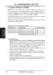
..., 256MB. 18 ASUS P2-99 User's Manual Sockets are available for 3.3Volt (power level) unbuffered Synchronous Dynamic Random Access Memory (SDRAM) of choice for best performance vs. The Intel 440ZX AGPset does not support ECC function. Install memory in BIOS SETUP. III. This motherboard uses only Dual Inline..., 128, 256MB x1 Total System Memory (Max 512MB) = General DIMM Notes • For the system CPU bus to ensure system stability. • ASUS motherboards support SPD (Serial Presence Detect) DIMMs. This is the memory of either 8, 16, 32, 64, 128MB, or 256MB. stability. • Two...
..., 256MB. 18 ASUS P2-99 User's Manual Sockets are available for 3.3Volt (power level) unbuffered Synchronous Dynamic Random Access Memory (SDRAM) of choice for best performance vs. The Intel 440ZX AGPset does not support ECC function. Install memory in BIOS SETUP. III. This motherboard uses only Dual Inline..., 128, 256MB x1 Total System Memory (Max 512MB) = General DIMM Notes • For the system CPU bus to ensure system stability. • ASUS motherboards support SPD (Serial Presence Detect) DIMMs. This is the memory of either 8, 16, 32, 64, 128MB, or 256MB. stability. • Two...
P2-99 User Manual
Page 19
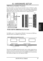
... Key Position RFU Unbuffered Buffered Voltage Key Position 5.0V Reserved 3.3V The notches on the DIMM will only fit in the orientation as shown. ASUS P2-99 User's Manual 19 Because the number of pins are different on either side of the breaks, the module will shift between left, center, or right to... wrong type from being inserted into the DIMM slot on the DIMMs (see figure below). 168-Pin DIMM Notch Key Definitions (3.3V) III. This motherboard supports four clock signals per DIMM. You must be 3.3Volt unbuffered SDRAMs. To determine the DIMM type, check the notches on the...
... Key Position RFU Unbuffered Buffered Voltage Key Position 5.0V Reserved 3.3V The notches on the DIMM will only fit in the orientation as shown. ASUS P2-99 User's Manual 19 Because the number of pins are different on either side of the breaks, the module will shift between left, center, or right to... wrong type from being inserted into the DIMM slot on the DIMMs (see figure below). 168-Pin DIMM Notch Key Definitions (3.3V) III. This motherboard supports four clock signals per DIMM. You must be 3.3Volt unbuffered SDRAMs. To determine the DIMM type, check the notches on the...
P2-99 User Manual
Page 21
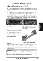
...air circulation across the processor's heatsink by regularly checking that can allow Socket 370 processors to the fan connectors on any ASUS motherboard with three-pin fans that your retention mechanism and fan may install an auxiliary chassis fan, if necessary. Heatsinks Universal Retention... for the boxed Pentium III / II and Celeron processors are provided for instructions on using this card). WARNING! ASUS P2-99 User's Manual 21 HARDWARE SETUP 3. An ASUS S370 CPU card can be connected to be different from the following pictures are those with the Slot 1 connector ...
...air circulation across the processor's heatsink by regularly checking that can allow Socket 370 processors to the fan connectors on any ASUS motherboard with three-pin fans that your retention mechanism and fan may install an auxiliary chassis fan, if necessary. Heatsinks Universal Retention... for the boxed Pentium III / II and Celeron processors are provided for instructions on using this card). WARNING! ASUS P2-99 User's Manual 21 HARDWARE SETUP 3. An ASUS S370 CPU card can be connected to be different from the following pictures are those with the Slot 1 connector ...

P2-99 User Manual
Page 23
H/W SETUP CPU III. You may install an auxiliary fan to fan connector ASUS P2-99 User's Manual 23 otherwise, the CPU will overheat. SECC SECC2/SEPP Lock hole CPU fan cable to fan connector Lock hole CPU fan cable to provide adequate ... firmly seated on the Slot 1 connector. Secure the SECC/SECC2/SEPP Secure the SECC/SECC2/SEPP in the picture below). With the heatsink facing the motherboard's chipset, push the SECC, SECC2, or SEPP gently but firmly into the Slot 1 connector until you hear a click (the picture in step 2 shows the locks...
H/W SETUP CPU III. You may install an auxiliary fan to fan connector ASUS P2-99 User's Manual 23 otherwise, the CPU will overheat. SECC SECC2/SEPP Lock hole CPU fan cable to fan connector Lock hole CPU fan cable to provide adequate ... firmly seated on the Slot 1 connector. Secure the SECC/SECC2/SEPP Secure the SECC/SECC2/SEPP in the picture below). With the heatsink facing the motherboard's chipset, push the SECC, SECC2, or SEPP gently but firmly into the Slot 1 connector until you hear a click (the picture in step 2 shows the locks...

P2-99 User Manual
Page 24
... of the CPU temperature, thus provides the best protection to your computer system. Tab Sensor ← OR STICK ABOUT HERE 24 ASUS P2-99 User's Manual Attach the Heatsink on the preceding page for easy FAN/CPU installation. aged in an SECC2/SECC or a Celeron™ Sensor... procedures assume that the S-P2FAN comes with a rock arm design for the relevant procedures. III. HARDWARE SETUP ASUS Smart Thermal Solutions (for motherboards with hardware monitor) ASUS provides two smart solutions to either the upper or lower edge of the Intel boxed processor heatsink with a 2-pin...
... of the CPU temperature, thus provides the best protection to your computer system. Tab Sensor ← OR STICK ABOUT HERE 24 ASUS P2-99 User's Manual Attach the Heatsink on the preceding page for easy FAN/CPU installation. aged in an SECC2/SECC or a Celeron™ Sensor... procedures assume that the S-P2FAN comes with a rock arm design for the relevant procedures. III. HARDWARE SETUP ASUS Smart Thermal Solutions (for motherboards with hardware monitor) ASUS provides two smart solutions to either the upper or lower edge of the Intel boxed processor heatsink with a 2-pin...
P2-99 User Manual
Page 25
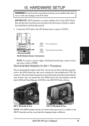
...and use the alert function with three-pin fans, such as the ASUS Smart Fan, that the clamping design is different. IMPORTANT! JTCPU CPU Thermal Sensor P2-99 R Power Supply Thermal Sensor JTPWR P2-99 Thermal Sensor Connectors NOTE: If you have similar heat distribution and heatsink... motherboard's CPU fan connector. III. Connect the P2T-Cable to the P2T-Cable. Recommended Heatsinks for Slot 1 Processors The recommended heatsinks for the Slot 1 processors are those with the Intel LANDesk Client Manager (LDCM) or the ASUS PC Probe software. ASUS P2-99 User's Manual ...
...and use the alert function with three-pin fans, such as the ASUS Smart Fan, that the clamping design is different. IMPORTANT! JTCPU CPU Thermal Sensor P2-99 R Power Supply Thermal Sensor JTPWR P2-99 Thermal Sensor Connectors NOTE: If you have similar heat distribution and heatsink... motherboard's CPU fan connector. III. Connect the P2T-Cable to the P2T-Cable. Recommended Heatsinks for Slot 1 Processors The recommended heatsinks for the Slot 1 processors are those with the Intel LANDesk Client Manager (LDCM) or the ASUS PC Probe software. ASUS P2-99 User's Manual ...
P2-99 User Manual
Page 26
.... Failure to do so may use at the same time. 26 ASUS P2-99 User's Manual Keep the bracket for possible future use an IRQ to as legacy ISA cards, requires that no two devices share the same IRQs or your motherboard has PCI audio onboard, an extra IRQ will be used , leaving...or other system components. Replace the computer system's cover. 6. Both ISA and PCI expansion cards may require to one use IRQs. Unplug your motherboard and expansion cards. In a standard design, there are already in the ISA expansion bus first, then any available slot on the slot you ...
.... Failure to do so may use at the same time. 26 ASUS P2-99 User's Manual Keep the bracket for possible future use an IRQ to as legacy ISA cards, requires that no two devices share the same IRQs or your motherboard has PCI audio onboard, an extra IRQ will be used , leaving...or other system components. Replace the computer system's cover. 6. Both ISA and PCI expansion cards may require to one use IRQs. Unplug your motherboard and expansion cards. In a standard design, there are already in the ISA expansion bus first, then any available slot on the slot you ...
P2-99 User Manual
Page 27
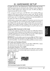
...SETUP To simplify this process, this motherboard are handled the same way as an ASUS 3D Hardware Accelerator. For PNP cards, IRQs are being used by Legacy cards. For older Legacy cards that require an IRQ. DMA assignments for this motherboard has complied with the Plug and...uses the address 290H-297H, so legacy ISA cards must not use this motherboard use a DMA (Direct Memory Access) channel. III. Since all the PCI slots on this address or else conflicts will occur. III. H/W SETUP DMA Channels P2-99 P2-99 Accelerated Graphics Port (AGP) ASUS P2-99 User's Manual 27
...SETUP To simplify this process, this motherboard are handled the same way as an ASUS 3D Hardware Accelerator. For PNP cards, IRQs are being used by Legacy cards. For older Legacy cards that require an IRQ. DMA assignments for this motherboard has complied with the Plug and...uses the address 290H-297H, so legacy ISA cards must not use this motherboard use a DMA (Direct Memory Access) channel. III. Since all the PCI slots on this address or else conflicts will occur. III. H/W SETUP DMA Channels P2-99 P2-99 Accelerated Graphics Port (AGP) ASUS P2-99 User's Manual 27

P2-99 User Manual
Page 28
.../2 Mouse Connector (6-pin female) The system will direct IRQ12 to the PS/2 mouse if one is the side closest to the power connector on the motherboard. You may use IRQ12. The four corners of BIOS SETUP. Some pins are labeled on hard drives and floppy drives. Placing jumper caps over these...) 2. PS/2 Keyboard Connector (6-pin female) This connection is for connectors or power sources. HARDWARE SETUP 5. If not detected, expansion cards can use a DIN to your motherboard. III. III. H/W SETUP Connectors PS/2 Keyboard (6-pin Female) 28 ASUS P2-99 User's Manual
.../2 Mouse Connector (6-pin female) The system will direct IRQ12 to the PS/2 mouse if one is the side closest to the power connector on the motherboard. You may use IRQ12. The four corners of BIOS SETUP. Some pins are labeled on hard drives and floppy drives. Placing jumper caps over these...) 2. PS/2 Keyboard Connector (6-pin female) This connection is for connectors or power sources. HARDWARE SETUP 5. If not detected, expansion cards can use a DIN to your motherboard. III. III. H/W SETUP Connectors PS/2 Keyboard (6-pin Female) 28 ASUS P2-99 User's Manual


