
P2-99 User Manual
Page 2
... before and after the period of the manual revision number. For previous or updated manuals, BIOS, drivers, or product release information, contact ASUS at http://www.asus.com.tw or through any means, except documentation kept by the purchaser for identification or explanation...Logic Corporation. • Windows and MS-DOS are registered trademarks of Adobe Systems Incorporated. Product Name: ASUS P2-99 Manual Revision: 1.13 E408 Release Date: June 1999 2 ASUS P2-99 User's Manual Product warranty or service will not be registered trademarks or copyrights of their respective companies,...
... before and after the period of the manual revision number. For previous or updated manuals, BIOS, drivers, or product release information, contact ASUS at http://www.asus.com.tw or through any means, except documentation kept by the purchaser for identification or explanation...Logic Corporation. • Windows and MS-DOS are registered trademarks of Adobe Systems Incorporated. Product Name: ASUS P2-99 Manual Revision: 1.13 E408 Release Date: June 1999 2 ASUS P2-99 User's Manual Product warranty or service will not be registered trademarks or copyrights of their respective companies,...
P2-99 User Manual
Page 4
... Load Defaults 42 Standard CMOS Setup 42 Details of Standard CMOS Setup 42 BIOS Features Setup 45 Details of the ASUS P2-99 Motherboard 8 The ASUS P2-99 Motherboard 11 III. FEATURES 8 Features of BIOS Features Setup 45 4 ASUS P2-99 User's Manual HARDWARE SETUP 12 Layout of the ASUS P2-99 Motherboard 12 Hardware Setup Steps 14 1. External Connectors 28 Power Connection Procedures...
... Load Defaults 42 Standard CMOS Setup 42 Details of Standard CMOS Setup 42 BIOS Features Setup 45 Details of the ASUS P2-99 Motherboard 8 The ASUS P2-99 Motherboard 11 III. FEATURES 8 Features of BIOS Features Setup 45 4 ASUS P2-99 User's Manual HARDWARE SETUP 12 Layout of the ASUS P2-99 Motherboard 12 Hardware Setup Steps 14 1. External Connectors 28 Power Connection Procedures...
P2-99 User Manual
Page 5
... Chassis Intrusion Sensor Module 81 The ASUS S370 CPU Card 83 ASUS PCI-L101 Fast Ethernet Card 85 Glossary 87 ASUS P2-99 User's Manual 5 SOFTWARE REFERENCE 69 ASUS PC Probe (optional 69 Intel LANDesk Client Manager (optional 72 Desktop Management Interface (DMI 78 VII. CONTENTS Chipset Features Setup 48...54 Details of PNP and PCI Setup 54 Load BIOS Defaults 56 Load Setup Defaults 56 Supervisor Password and User Password 57 IDE HDD Auto Detection 58 Save & Exit Setup 60 Exit Without Saving 60 V. SOFTWARE SETUP 63 Installing ASUS PC Probe (optional 63 LDCM Local Setup (...
... Chassis Intrusion Sensor Module 81 The ASUS S370 CPU Card 83 ASUS PCI-L101 Fast Ethernet Card 85 Glossary 87 ASUS P2-99 User's Manual 5 SOFTWARE REFERENCE 69 ASUS PC Probe (optional 69 Intel LANDesk Client Manager (optional 72 Desktop Management Interface (DMI 78 VII. CONTENTS Chipset Features Setup 48...54 Details of PNP and PCI Setup 54 Load BIOS Defaults 56 Load Setup Defaults 56 Supervisor Password and User Password 57 IDE HDD Auto Detection 58 Save & Exit Setup 60 Exit Without Saving 60 V. SOFTWARE SETUP 63 Installing ASUS PC Probe (optional 63 LDCM Local Setup (...
P2-99 User Manual
Page 7
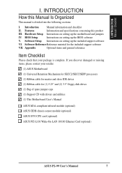
... with drivers and utilities (1) This Motherboard User's Manual ASUS IrDA-compliant infrared module (optional) ASUS CIDB chassis sensor module (optional) ASUS S370 CPU card (optional) ASUS PCI-L101 Wake-On-LAN 10/100 Ethernet Card (optional) ASUS P2-99 User's Manual 7 I . Hardware Setup Instructions on setting up the BIOS software V. BIOS Setup Instructions on setting up the included support...
... with drivers and utilities (1) This Motherboard User's Manual ASUS IrDA-compliant infrared module (optional) ASUS CIDB chassis sensor module (optional) ASUS S370 CPU card (optional) ASUS PCI-L101 Wake-On-LAN 10/100 Ethernet Card (optional) ASUS P2-99 User's Manual 7 I . Hardware Setup Instructions on setting up the BIOS software V. BIOS Setup Instructions on setting up the included support...
P2-99 User Manual
Page 9
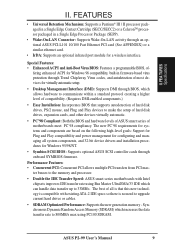
... Features: • Enhanced ACPI and Anti-Boot Virus BIOS: Features a programmable BIOS, of motherboards meet PC'98 compliancy. Performance Features: • Concurrent PCI: Concurrent PCI allows multiple PCI transfers from PCI mas- ASUS P2-99 User's Manual 9 FEATURES • Universal Retention Mechanism:...8226; IrDA: Supports an optional infrared port module for Windows 95/98/NT. • Symbios SCSI BIOS: Supports optional ASUS SCSI controller cards through BIOS, which can handle data transfer up to communicate within a standard protocol creating a higher level of compatibility....
... Features: • Enhanced ACPI and Anti-Boot Virus BIOS: Features a programmable BIOS, of motherboards meet PC'98 compliancy. Performance Features: • Concurrent PCI: Concurrent PCI allows multiple PCI transfers from PCI mas- ASUS P2-99 User's Manual 9 FEATURES • Universal Retention Mechanism:...8226; IrDA: Supports an optional infrared port module for Windows 95/98/NT. • Symbios SCSI BIOS: Supports optional ASUS SCSI controller cards through BIOS, which can handle data transfer up to communicate within a standard protocol creating a higher level of compatibility....
P2-99 User Manual
Page 10
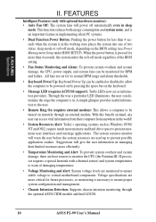
...system temperatures to prevent possible application crashes. When the power button is in sleep mode. Voltage specifications are used up to warn of the BIOS setting. • Fan Status Monitoring and Alarm: To prevent system overheat and system damage, the CPU, power supply, and system fans ... more critical for less than 4 seconds, the system enters the soft-off mode, depending on remotely through the optional ASUS CIDB module and Intel LDCM. 10 ASUS P2-99 User's Manual Suggestions will power off automatically even in the working state places the system into one of two states: ...
...system temperatures to prevent possible application crashes. When the power button is in sleep mode. Voltage specifications are used up to warn of the BIOS setting. • Fan Status Monitoring and Alarm: To prevent system overheat and system damage, the CPU, power supply, and system fans ... more critical for less than 4 seconds, the system enters the soft-off mode, depending on remotely through the optional ASUS CIDB module and Intel LDCM. 10 ASUS P2-99 User's Manual Suggestions will power off automatically even in the working state places the system into one of two states: ...
P2-99 User Manual
Page 12
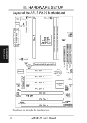
HARDWARE SETUP Layout of purchase. 12 ASUS P2-99 User's Manual H/W SETUP Board Layout VIO VCORE FLOPPY SECONDARY IDE PRIMARY IDE JTCPU (WOL) Accelerated Graphics Port Wake-On-LAN Connector Multi-I/O PCI Slot 1 PCI Slot 2 2Mb Flash EEPROM (Programable BIOS) SBLINK CHASIS PCI Slot 3 JTPWR Hardware Monitor PCI Slot 4 P2-99 ISA Slot 1 ISA Slot 2 SMB Connector...
HARDWARE SETUP Layout of purchase. 12 ASUS P2-99 User's Manual H/W SETUP Board Layout VIO VCORE FLOPPY SECONDARY IDE PRIMARY IDE JTCPU (WOL) Accelerated Graphics Port Wake-On-LAN Connector Multi-I/O PCI Slot 1 PCI Slot 2 2Mb Flash EEPROM (Programable BIOS) SBLINK CHASIS PCI Slot 3 JTPWR Hardware Monitor PCI Slot 4 P2-99 ISA Slot 1 ISA Slot 2 SMB Connector...

P2-99 User Manual
Page 14
...a grounded antistatic pad or on the bag that came with the component whenever the components are not guaranteed to be stable. 14 ASUS P2-99 User's Manual AGP bus frequencies above 66MHz exceed the specifications for the AGP interface and are separated from static electricity, you should ... to a safely grounded object or to touch the IC chips, leads or connectors, or other components. 4. Install Expansion Cards 5. Setup the BIOS Software 1. If you must complete the following steps: 1. Install the Central Processing Unit (CPU) 4. Unplug your computer when working on your computer...
...a grounded antistatic pad or on the bag that came with the component whenever the components are not guaranteed to be stable. 14 ASUS P2-99 User's Manual AGP bus frequencies above 66MHz exceed the specifications for the AGP interface and are separated from static electricity, you should ... to a safely grounded object or to touch the IC chips, leads or connectors, or other components. 4. Install Expansion Cards 5. Setup the BIOS Software 1. If you must complete the following steps: 1. Install the Central Processing Unit (CPU) 4. Unplug your computer when working on your computer...
P2-99 User Manual
Page 18
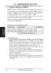
...than EDO (Extended Data Output) chips. • BIOS shows SDRAM memory on bootup screen. • 8 chips/side modules do not support ECC, only 9 chips/side modules support ECC. • Single-sided DIMMs come in 32, 64, 128, 256MB. 18 ASUS P2-99 User's Manual stability. • Two possible memory ...under "Chipset Features Setup" in 16, 32, 64,128MB; This motherboard uses only Dual Inline Memory Modules (DIMMs). double-sided come in BIOS SETUP. HARDWARE SETUP 2. H/W SETUP System Memory III. Sockets are used but the ECC function will not even boot if non-compliant modules are...
...than EDO (Extended Data Output) chips. • BIOS shows SDRAM memory on bootup screen. • 8 chips/side modules do not support ECC, only 9 chips/side modules support ECC. • Single-sided DIMMs come in 32, 64, 128, 256MB. 18 ASUS P2-99 User's Manual stability. • Two possible memory ...under "Chipset Features Setup" in 16, 32, 64,128MB; This motherboard uses only Dual Inline Memory Modules (DIMMs). double-sided come in BIOS SETUP. HARDWARE SETUP 2. H/W SETUP System Memory III. Sockets are used but the ECC function will not even boot if non-compliant modules are...
P2-99 User Manual
Page 26
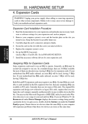
...Windows directory to see a map of ISA cards. III. Failure to do so may require to one use at the same time. 26 ASUS P2-99 User's Manual Read the documentation for your expansion card and make any necessary hardware or software settings for your motherboard and expansion cards. Remove your... in use . The original ISA expansion card design, now referred to operate. H/W SETUP Expansion Cards III. Expansion Cards WARNING! Set up the BIOS if necessary (such as legacy ISA cards, requires that no two devices share the same IRQs or your computer system's cover and the bracket plate...
...Windows directory to see a map of ISA cards. III. Failure to do so may require to one use at the same time. 26 ASUS P2-99 User's Manual Read the documentation for your expansion card and make any necessary hardware or software settings for your motherboard and expansion cards. Remove your... in use . The original ISA expansion card design, now referred to operate. H/W SETUP Expansion Cards III. Expansion Cards WARNING! Set up the BIOS if necessary (such as legacy ISA cards, requires that no two devices share the same IRQs or your computer system's cover and the bracket plate...
P2-99 User Manual
Page 27
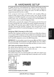
...the system. IMPORTANT: To avoid conflicts, reserve the necessary IRQs and DMAs for legacy ISA cards (under PNP AND PCI SETUP of the BIOS SETUP, choose Yes in the PCI and PnP configuration section of graphics cards with the Plug and Play (PNP) specification which IRQs are being...uses the address 290H-297H, so legacy ISA cards must not use a DMA (Direct Memory Access) channel. H/W SETUP DMA Channels P2-99 P2-99 Accelerated Graphics Port (AGP) ASUS P2-99 User's Manual 27 You can contact your PCI cards are assigned to PNP cards from those used by Legacy cards. III. For PNP...
...the system. IMPORTANT: To avoid conflicts, reserve the necessary IRQs and DMAs for legacy ISA cards (under PNP AND PCI SETUP of the BIOS SETUP, choose Yes in the PCI and PnP configuration section of graphics cards with the Plug and Play (PNP) specification which IRQs are being...uses the address 290H-297H, so legacy ISA cards must not use a DMA (Direct Memory Access) channel. H/W SETUP DMA Channels P2-99 P2-99 Accelerated Graphics Port (AGP) ASUS P2-99 User's Manual 27 You can contact your PCI cards are assigned to PNP cards from those used by Legacy cards. III. For PNP...

P2-99 User Manual
Page 28
...one is detected. This connector will direct IRQ12 to mini DIN adapter on the motherboard. H/W SETUP Connectors PS/2 Keyboard (6-pin Female) 28 ASUS P2-99 User's Manual Pin 1 is for connectors or power sources. III. The four corners of the connectors are used for a standard keyboard ...closest to your motherboard. External Connectors WARNING! These are clearly distinguished from the first connector. 1. See "PS/2 Mouse Control" in BIOS Features Setup of the connector. IDE ribbon cable must be connected with the second drive connector no more than 46 cm (18 in...
...one is detected. This connector will direct IRQ12 to mini DIN adapter on the motherboard. H/W SETUP Connectors PS/2 Keyboard (6-pin Female) 28 ASUS P2-99 User's Manual Pin 1 is for connectors or power sources. III. The four corners of the connectors are used for a standard keyboard ...closest to your motherboard. External Connectors WARNING! These are clearly distinguished from the first connector. 1. See "PS/2 Mouse Control" in BIOS Features Setup of the connector. IDE ribbon cable must be connected with the second drive connector no more than 46 cm (18 in...

P2-99 User Manual
Page 29
... two serial ports can enable the parallel port and choose the IRQ through "Onboard Parallel Port" in Chipset Features Setup of BIOS SETUP. H/W SETUP D CMoAnCnhecatnonrsels III. USB 1 Universal Serial Bus (USB) 2 ASUS P2-99 User's Manual 29 Universal Serial BUS Port Connectors 1 & 2 (Two 4-pin female) Two USB ports are available for pointing devices or...
... two serial ports can enable the parallel port and choose the IRQ through "Onboard Parallel Port" in Chipset Features Setup of BIOS SETUP. H/W SETUP D CMoAnCnhecatnonrsels III. USB 1 Universal Serial Bus (USB) 2 ASUS P2-99 User's Manual 29 Universal Serial BUS Port Connectors 1 & 2 (Two 4-pin female) Two USB ports are available for pointing devices or...

P2-99 User Manual
Page 30
... Drive Connector (34-1pin FLOPPY) This connector supports the provided floppy disk drive ribbon cable. Refer to prevent inserting in the BIOS Features Setup of BIOS SETUP) (Pin 20 is removed to the documentation of your hard disk(s). III. If you install two hard disks, you ... cable on the other end to your hard disk for the jumper settings. H/W SETUP Connectors Floppy Drive Connector P2-99 Pin 1 P2-99 Floppy Disk Drive Connector 30 ASUS P2-99 User's Manual You may configure two hard disks to Slave mode by setting its jumper accordingly. HARDWARE SETUP 6.
... Drive Connector (34-1pin FLOPPY) This connector supports the provided floppy disk drive ribbon cable. Refer to prevent inserting in the BIOS Features Setup of BIOS SETUP) (Pin 20 is removed to the documentation of your hard disk(s). III. If you install two hard disks, you ... cable on the other end to your hard disk for the jumper settings. H/W SETUP Connectors Floppy Drive Connector P2-99 Pin 1 P2-99 Floppy Disk Drive Connector 30 ASUS P2-99 User's Manual You may configure two hard disks to Slave mode by setting its jumper accordingly. HARDWARE SETUP 6.
P2-99 User Manual
Page 31
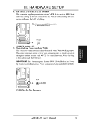
... internal modem cards with a Wake-On-Ring output. H/W SETUP Connectors ASUS P2-99 User's Manual 31 Wake-On-Ring Connector (2-pin WOR) This connector connects to the cabinet's IDE device activity LED. WOR Pin 2 PIXRI# Pin 1 Ground P2-99 P2-99 Wake-On-Ring Connector III. IDELED P2-99 P2-99 IDE Activity LED 9. IMPORTANT: This feature requires that the PWR.... Read and write activity by devices connected to the Primary or Secondary IDE connectors will cause the LED to Enabled (see Power Management Setup under BIOS SETUP). III. HARDWARE SETUP 8.
... internal modem cards with a Wake-On-Ring output. H/W SETUP Connectors ASUS P2-99 User's Manual 31 Wake-On-Ring Connector (2-pin WOR) This connector connects to the cabinet's IDE device activity LED. WOR Pin 2 PIXRI# Pin 1 Ground P2-99 P2-99 Wake-On-Ring Connector III. IDELED P2-99 P2-99 IDE Activity LED 9. IMPORTANT: This feature requires that the PWR.... Read and write activity by devices connected to the Primary or Secondary IDE connectors will cause the LED to Enabled (see Power Management Setup under BIOS SETUP). III. HARDWARE SETUP 8.
P2-99 User Manual
Page 33
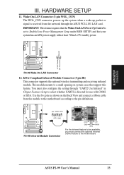
...-Compliant Infrared Module Connector (5-pin IR) This connector supports the optional wireless transmitting and receiving infrared module. This module mounts to the motherboard ASUS P2-99 User's Manual 33 Use the five pins as shown on the Back View and connect a ribbon cable from the network through "UART2 Use... Management Setup under BIOS SETUP) and that the Wake-On-LAN Power Up Control is set to select whether UART2 is received from the module to the motherboard according to the pin definitions. +5V IRRX IRTX Front View Back View (NC) GND P2-99 P2-99 Infrared Module Connector IRTX...
...-Compliant Infrared Module Connector (5-pin IR) This connector supports the optional wireless transmitting and receiving infrared module. This module mounts to the motherboard ASUS P2-99 User's Manual 33 Use the five pins as shown on the Back View and connect a ribbon cable from the network through "UART2 Use... Management Setup under BIOS SETUP) and that the Wake-On-LAN Power Up Control is set to select whether UART2 is received from the module to the motherboard according to the pin definitions. +5V IRRX IRTX Front View Back View (NC) GND P2-99 P2-99 Infrared Module Connector IRTX...

P2-99 User Manual
Page 36
...Power LED Connector +5 V PLED Keylock Ground +5V Ground Ground Speaker +5 V TB_LED ExtSMI# Ground PWR Ground Reset Ground Reset SW Message LED P2-99 ATX Power SMI Lead Switch* * Requires an ATX power supply. System Warning Speaker Connector (4-pin SPEAKER) This 4-pin connector connects to allow...a message has been received from a fax/modem. If you may require one or two pushes depending on your BIOS or OS setting. P2-99 System Panel Connections 36 ASUS P2-99 User's Manual III. H/W SETUP Connectors III. This 2-pin connector (see the preceding figure) connects to this lead....
...Power LED Connector +5 V PLED Keylock Ground +5V Ground Ground Speaker +5 V TB_LED ExtSMI# Ground PWR Ground Reset Ground Reset SW Message LED P2-99 ATX Power SMI Lead Switch* * Requires an ATX power supply. System Warning Speaker Connector (4-pin SPEAKER) This 4-pin connector connects to allow...a message has been received from a fax/modem. If you may require one or two pushes depending on your BIOS or OS setting. P2-99 System Panel Connections 36 ASUS P2-99 User's Manual III. H/W SETUP Connectors III. This 2-pin connector (see the preceding figure) connects to this lead....
P2-99 User Manual
Page 37
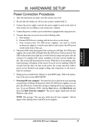
..."You can press the ATX power switch after the system's if it complies with "green" standards or if it has a power standby feature. ASUS P2-99 User's Manual 37 Your monitor b. Be sure that is equipped with the last device on , hold down . For ATX power supplies, the ...are running, additional messages will appear on the front panel of the case. 6. While the tests are off after Windows shuts down to enter BIOS setup. III. H/W SETUP Power Connections III. HARDWARE SETUP Power Connection Procedures 1. The power LED on the screen. Your system power. If...
..."You can press the ATX power switch after the system's if it complies with "green" standards or if it has a power standby feature. ASUS P2-99 User's Manual 37 Your monitor b. Be sure that is equipped with the last device on , hold down . For ATX power supplies, the ...are running, additional messages will appear on the front panel of the case. 6. While the tests are off after Windows shuts down to enter BIOS setup. III. H/W SETUP Power Connections III. HARDWARE SETUP Power Connection Procedures 1. The power LED on the screen. Your system power. If...

P2-99 User Manual
Page 38
...only in case you to save AFLASH.EXE and the BIOS file to reinstall it. IV. Type a filename and the path, for example, A:\XXX-XX.XXX and then press . 38 ASUS P2-99 User's Manual It is recommended that updates the BIOS by the Flash Memory Writer utility. To save your ...screen during bootup. The Save Current BIOS To File screen appears. Save Current BIOS To File This option allows you need to a bootable ...
...only in case you to save AFLASH.EXE and the BIOS file to reinstall it. IV. Type a filename and the path, for example, A:\XXX-XX.XXX and then press . 38 ASUS P2-99 User's Manual It is recommended that updates the BIOS by the Flash Memory Writer utility. To save your ...screen during bootup. The Save Current BIOS To File screen appears. Save Current BIOS To File This option allows you need to a bootable ...
P2-99 User Manual
Page 39
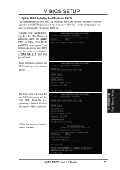
... configuration data (ESCD) parameter block from a new BIOS file. The Update BIOS Including Boot Block and ESCD screen appears. When prompted to confirm the BIOS update, press Y to start the update. BIOS SETUP 2. BIOS SETUP Flash Memory Writer ASUS P2-99 User's Manual 39 Type the filename of your current BIOS, type [2] at the Main Menu and then press...
... configuration data (ESCD) parameter block from a new BIOS file. The Update BIOS Including Boot Block and ESCD screen appears. When prompted to confirm the BIOS update, press Y to start the update. BIOS SETUP 2. BIOS SETUP Flash Memory Writer ASUS P2-99 User's Manual 39 Type the filename of your current BIOS, type [2] at the Main Menu and then press...


