P2-99 User Manual
Page 1
® P2-99 Pentium® III / II / CeleronTM Motherboard USER'S MANUAL
® P2-99 Pentium® III / II / CeleronTM Motherboard USER'S MANUAL
P2-99 User Manual
Page 4
... BIOS Features Setup 45 4 ASUS P2-99 User's Manual BIOS Setup 41 Load Defaults 42 Standard CMOS Setup 42 Details of Standard CMOS Setup 42 BIOS Features Setup 45 Details of the ASUS P2-99 Motherboard 12 Hardware Setup Steps 14 1. Motherboard Settings 14 Jumpers 14 2. .... BIOS SETUP 38 Flash Memory Writer Utility 38 Main Menu 38 Managing and Updating Your Motherboard's BIOS 40 6. FEATURES 8 Features of the ASUS P2-99 Motherboard 8 The ASUS P2-99 Motherboard 11 III. CONTENTS I. Expansion Cards 26 Expansion Card Installation Procedure 26 Assigning IRQs for...
... BIOS Features Setup 45 4 ASUS P2-99 User's Manual BIOS Setup 41 Load Defaults 42 Standard CMOS Setup 42 Details of Standard CMOS Setup 42 BIOS Features Setup 45 Details of the ASUS P2-99 Motherboard 12 Hardware Setup Steps 14 1. Motherboard Settings 14 Jumpers 14 2. .... BIOS SETUP 38 Flash Memory Writer Utility 38 Main Menu 38 Managing and Updating Your Motherboard's BIOS 40 6. FEATURES 8 Features of the ASUS P2-99 Motherboard 8 The ASUS P2-99 Motherboard 11 III. CONTENTS I. Expansion Cards 26 Expansion Card Installation Procedure 26 Assigning IRQs for...
P2-99 User Manual
Page 7
... caps (1) Support CD with drivers and utilities (1) This Motherboard User's Manual ASUS IrDA-compliant infrared module (optional) ASUS CIDB chassis sensor module (optional) ASUS S370 CPU card (optional) ASUS PCI-L101 Wake-On-LAN 10/100 Ethernet Card (optional) ASUS P2-99 User's Manual 7 Software Setup Instructions on setting up the motherboard and jumpers IV. Hardware Setup Instructions on setting up...
... caps (1) Support CD with drivers and utilities (1) This Motherboard User's Manual ASUS IrDA-compliant infrared module (optional) ASUS CIDB chassis sensor module (optional) ASUS S370 CPU card (optional) ASUS PCI-L101 Wake-On-LAN 10/100 Ethernet Card (optional) ASUS P2-99 User's Manual 7 Software Setup Instructions on setting up the motherboard and jumpers IV. Hardware Setup Instructions on setting up...
P2-99 User Manual
Page 8
... connections. • UltraDMA/33 Bus Master IDE: Comes with an onboard PCI Bus Master IDE controller with EPP and ECP capabilities. FEATURES Features of the ASUS P2-99 Motherboard The ASUS P2-99 is carefully designed for the demanding PC user who wants advanced features processed by Intel or PC Probe from...) up functions from COM2 to examine and manage system status information such as Tape Backup and CD-ROM, CD-R, CD-RW, and LS-120 drives. 8 ASUS P2-99 User's Manual II.
... connections. • UltraDMA/33 Bus Master IDE: Comes with an onboard PCI Bus Master IDE controller with EPP and ECP capabilities. FEATURES Features of the ASUS P2-99 Motherboard The ASUS P2-99 is carefully designed for the demanding PC user who wants advanced features processed by Intel or PC Probe from...) up functions from COM2 to examine and manage system status information such as Tape Backup and CD-ROM, CD-R, CD-RW, and LS-120 drives. 8 ASUS P2-99 User's Manual II.
P2-99 User Manual
Page 9
...allows multiple PCI transfers from PCI mas- ter busses to the memory and processor. • Double the IDE Transfer Speed: ASUS smart series motherboards with existing ATA-2 IDE specs so there is no need to 33MB/s. Synchronous Dynamic Random Access Memory (SDRAM) which can .... • PC'98 Compliant: Both the BIOS and hardware levels of ASUS smart series of - ASUS P2-99 User's Manual 9 Special Features: • Enhanced ACPI and Anti-Boot Virus BIOS: Features a programmable BIOS, of motherboards meet PC'98 compliancy. FEA TURES Specifications II. The new PC'98 ...
...allows multiple PCI transfers from PCI mas- ter busses to the memory and processor. • Double the IDE Transfer Speed: ASUS smart series motherboards with existing ATA-2 IDE specs so there is no need to 33MB/s. Synchronous Dynamic Random Access Memory (SDRAM) which can .... • PC'98 Compliant: Both the BIOS and hardware levels of ASUS smart series of - ASUS P2-99 User's Manual 9 Special Features: • Enhanced ACPI and Anti-Boot Virus BIOS: Features a programmable BIOS, of motherboards meet PC'98 compliancy. FEA TURES Specifications II. The new PC'98 ...
P2-99 User Manual
Page 10
... anywhere in sleep mode. The system resource monitor will give the user information on remotely through the optional ASUS CIDB module and Intel LDCM. 10 ASUS P2-99 User's Manual Voltage specifications are heat sensors to critical motherboard components. II. FEA TURES Specifications II. Suggestions will warn the user before the system resources are monitored to...
... anywhere in sleep mode. The system resource monitor will give the user information on remotely through the optional ASUS CIDB module and Intel LDCM. 10 ASUS P2-99 User's Manual Voltage specifications are heat sensors to critical motherboard components. II. FEA TURES Specifications II. Suggestions will warn the user before the system resources are monitored to...
P2-99 User Manual
Page 11
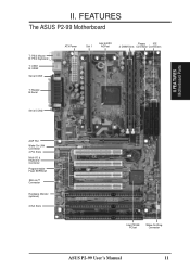
FEATURES The ASUS P2-99 Motherboard T: PS/2 Mouse B: PS/2 Keyboard T: USB1 B: USB2 Serial COM1 T: Parallel B:Serial ATX Power Slot 1 Intel 440ZX AGPset Floppy IDE 2 DIMM Slots Connector Connectors Serial COM2 II. II. FEA TURES Motherboard Parts AGP Port Wake-On-LAN Connector 4 PCI Slots Multi-I/O & Keyboard Controller Programmable Flash EEPROM SB-Link™ Connector Hardware Monitor (optional) 3 ISA Slots Intel PIIX4E PCIset Wake-On-Ring Connector ASUS P2-99 User's Manual 11
FEATURES The ASUS P2-99 Motherboard T: PS/2 Mouse B: PS/2 Keyboard T: USB1 B: USB2 Serial COM1 T: Parallel B:Serial ATX Power Slot 1 Intel 440ZX AGPset Floppy IDE 2 DIMM Slots Connector Connectors Serial COM2 II. II. FEA TURES Motherboard Parts AGP Port Wake-On-LAN Connector 4 PCI Slots Multi-I/O & Keyboard Controller Programmable Flash EEPROM SB-Link™ Connector Hardware Monitor (optional) 3 ISA Slots Intel PIIX4E PCIset Wake-On-Ring Connector ASUS P2-99 User's Manual 11
P2-99 User Manual
Page 12
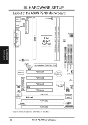
.... 12 ASUS P2-99 User's Manual H/W SETUP Board Layout VIO VCORE FLOPPY SECONDARY IDE PRIMARY IDE JTCPU (WOL) Accelerated Graphics Port Wake-On-LAN Connector Multi-I/O PCI Slot 1 PCI Slot 2 2Mb Flash EEPROM (Programable BIOS) SBLINK CHASIS PCI Slot 3 JTPWR Hardware Monitor PCI Slot 4 P2-99 ISA Slot...(CMOS Power) CHA_FAN CLRTC Intel PIIX4E PCIset WOR BUS FREQ BF3 BF2 BF1 BF0 ASUS ASIC IR IDE LED Panel Connectors Grayed items are optional at the time of the ASUS P2-99 Motherboard T: Mouse PS/2 B: Keyboard PWR_FAN CPU_FAN Parallel Port ATX Power Connector Slot 1 USB...
.... 12 ASUS P2-99 User's Manual H/W SETUP Board Layout VIO VCORE FLOPPY SECONDARY IDE PRIMARY IDE JTCPU (WOL) Accelerated Graphics Port Wake-On-LAN Connector Multi-I/O PCI Slot 1 PCI Slot 2 2Mb Flash EEPROM (Programable BIOS) SBLINK CHASIS PCI Slot 3 JTPWR Hardware Monitor PCI Slot 4 P2-99 ISA Slot...(CMOS Power) CHA_FAN CLRTC Intel PIIX4E PCIset WOR BUS FREQ BF3 BF2 BF1 BF0 ASUS ASIC IR IDE LED Panel Connectors Grayed items are optional at the time of the ASUS P2-99 Motherboard T: Mouse PS/2 B: Keyboard PWR_FAN CPU_FAN Parallel Port ATX Power Connector Slot 1 USB...
P2-99 User Manual
Page 13
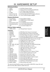
HARDWARE SETUP Motherboard Settings 1) AGPFS 2) KBPWR 3) VIO 4) VCORE 5) FS0, FS1, FS2, FS3 6) BF0, BF1, BF2, BF3 p. 14 AGP Bus Frequency Setting p. 15... pins) 13) SBLINK p. 34 SB-Link™ Port Connector (6-1 pins) 14) SMB CON. p. 34 SMBus Connector (3 pins) 15) ATXPWR p. 35 ATX Motherboard Power Connector (20 pins) 16) CHASIS p. 35 Chassis Intrusion Alarm Lead (4-1 pins) 17) PWR.LED (PANEL) 18) KEYLOCK (PANEL) 19) SPEAKER (PANEL)... so legacy ISA cards must not use this address otherwise conflicts will occur. H/W SETUP Layout Contents III. ASUS P2-99 User's Manual 13 III.
HARDWARE SETUP Motherboard Settings 1) AGPFS 2) KBPWR 3) VIO 4) VCORE 5) FS0, FS1, FS2, FS3 6) BF0, BF1, BF2, BF3 p. 14 AGP Bus Frequency Setting p. 15... pins) 13) SBLINK p. 34 SB-Link™ Port Connector (6-1 pins) 14) SMB CON. p. 34 SMBus Connector (3 pins) 15) ATXPWR p. 35 ATX Motherboard Power Connector (20 pins) 16) CHASIS p. 35 Chassis Intrusion Alarm Lead (4-1 pins) 17) PWR.LED (PANEL) 18) KEYLOCK (PANEL) 19) SPEAKER (PANEL)... so legacy ISA cards must not use this address otherwise conflicts will occur. H/W SETUP Layout Contents III. ASUS P2-99 User's Manual 13 III.

P2-99 User Manual
Page 14
... edges and try not to a metal object, such as the power supply case. 3. The default sets the AGP bus frequency to be stable. 14 ASUS P2-99 User's Manual Check Motherboard Settings 2. Jumpers 1. Install Memory Modules 3. III. AGP Frequency Setting (AGPFS) This option sets the frequency ratio between the AGP bus frequency and the CPU...
... edges and try not to a metal object, such as the power supply case. 3. The default sets the AGP bus frequency to be stable. 14 ASUS P2-99 User's Manual Check Motherboard Settings 2. Jumpers 1. Install Memory Modules 3. III. AGP Frequency Setting (AGPFS) This option sets the frequency ratio between the AGP bus frequency and the CPU...

P2-99 User Manual
Page 15
...computer will not function if you set to Disable because not all computers have the right ATX power supply. H/W SETUP Motherboard Settings III. Keyboard Power Up Setting (KBPWR) This allows you do not have the appropriate ATX power supply. This feature...voltage supplied to power up function. VIO 3 2 1 Normal 3 2 1 Test P2-99 P2-99 I /O Voltage Setting (VIO) This jumper allows you want to use your keyboard (by pressing ) to the DRAM, chipset, AGP, and the CPU's I/O buffer. I /O Voltage Setting ASUS P2-99 User's Manual 15 III. HARDWARE SETUP 2. Leave on the +5VSB lead.
...computer will not function if you set to Disable because not all computers have the right ATX power supply. H/W SETUP Motherboard Settings III. Keyboard Power Up Setting (KBPWR) This allows you do not have the appropriate ATX power supply. This feature...voltage supplied to power up function. VIO 3 2 1 Normal 3 2 1 Test P2-99 P2-99 I /O Voltage Setting (VIO) This jumper allows you want to use your keyboard (by pressing ) to the DRAM, chipset, AGP, and the CPU's I/O buffer. I /O Voltage Setting ASUS P2-99 User's Manual 15 III. HARDWARE SETUP 2. Leave on the +5VSB lead.
P2-99 User Manual
Page 18
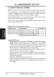
... 256MB x1 Total System Memory (Max 512MB) = General DIMM Notes • For the system CPU bus to ensure system stability. • ASUS motherboards support SPD (Serial Presence Detect) DIMMs. This is required after adding or removing memory. ECC memory modules may be available. H/W SETUP System ...at 100MHz, use only PC100-compliant DIMMs. When this speed. III. This motherboard uses only Dual Inline Memory Modules (DIMMs). double-sided come in 32, 64, 128, 256MB. 18 ASUS P2-99 User's Manual HARDWARE SETUP 2. The Intel 440ZX AGPset does not support ECC function. Install ...
... 256MB x1 Total System Memory (Max 512MB) = General DIMM Notes • For the system CPU bus to ensure system stability. • ASUS motherboards support SPD (Serial Presence Detect) DIMMs. This is required after adding or removing memory. ECC memory modules may be available. H/W SETUP System ...at 100MHz, use only PC100-compliant DIMMs. When this speed. III. This motherboard uses only Dual Inline Memory Modules (DIMMs). double-sided come in 32, 64, 128, 256MB. 18 ASUS P2-99 User's Manual HARDWARE SETUP 2. The Intel 440ZX AGPset does not support ECC function. Install ...
P2-99 User Manual
Page 19
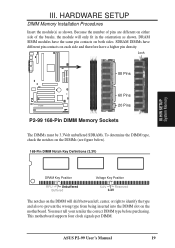
HARDWARE SETUP DIMM Memory Installation Procedures Insert the module(s) as shown. Lock 88 Pins 60 Pins P2-99 20 Pins P2-99 168-Pin DIMM Memory Sockets The DIMMs must tell your retailer the correct DIMM type before purchasing. Because the number of pins are different ... 3.3V The notches on the DIMM will only fit in the orientation as shown. DRAM SIMM modules have the same pin contacts on the motherboard. ASUS P2-99 User's Manual 19 You must be 3.3Volt unbuffered SDRAMs. To determine the DIMM type, check the notches on each side and therefore have different pin contacts...
HARDWARE SETUP DIMM Memory Installation Procedures Insert the module(s) as shown. Lock 88 Pins 60 Pins P2-99 20 Pins P2-99 168-Pin DIMM Memory Sockets The DIMMs must tell your retailer the correct DIMM type before purchasing. Because the number of pins are different ... 3.3V The notches on the DIMM will only fit in the orientation as shown. DRAM SIMM modules have the same pin contacts on the motherboard. ASUS P2-99 User's Manual 19 You must be 3.3Volt unbuffered SDRAMs. To determine the DIMM type, check the notches on each side and therefore have different pin contacts...
P2-99 User Manual
Page 21
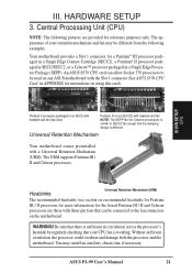
...Single Edge Processor Package (SEPP). The URM supports Pentium III / II and Celeron processors. You may be connected to be used on the motherboard. ASUS P2-99 User's Manual 21 III. Heatsinks Universal Retention Mechanism (URM) The recommended heatsinks (see section on recommended heatsinks for Pentium III / II processors for more ... across the processor's heatsink by regularly checking that can allow Socket 370 processors to the fan connectors on any ASUS motherboard with a Universal Retention Mechanism (URM). HARDWARE SETUP 3. Be sure that there is working.
...Single Edge Processor Package (SEPP). The URM supports Pentium III / II and Celeron processors. You may be connected to be used on the motherboard. ASUS P2-99 User's Manual 21 III. Heatsinks Universal Retention Mechanism (URM) The recommended heatsinks (see section on recommended heatsinks for Pentium III / II processors for more ... across the processor's heatsink by regularly checking that can allow Socket 370 processors to the fan connectors on any ASUS motherboard with a Universal Retention Mechanism (URM). HARDWARE SETUP 3. Be sure that there is working.

P2-99 User Manual
Page 23
...; SECC SECC2/SEPP Lock hole CPU fan cable to fan connector Lock hole CPU fan cable to fan connector ASUS P2-99 User's Manual 23 otherwise, the CPU will overheat. With the heatsink facing the motherboard's chipset, push the SECC, SECC2, or SEPP gently but firmly into the Slot 1 connector until it is firmly seated...
...; SECC SECC2/SEPP Lock hole CPU fan cable to fan connector Lock hole CPU fan cable to fan connector ASUS P2-99 User's Manual 23 otherwise, the CPU will overheat. With the heatsink facing the motherboard's chipset, push the SECC, SECC2, or SEPP gently but firmly into the Slot 1 connector until it is firmly seated...

P2-99 User Manual
Page 24
... 2-pin thermal sensor connector. aged in an SECC2/SECC or a Celeron™ Sensor processor packaged in a Slot 1 motherboard with fan (middle) or to your computer system. The sensor is a CPU fan for the relevant procedures. Sensor Connector Plug To ...ASUS provides two smart solutions to give the most accurate reading of the CPU heat source. ASUS S-P2FAN The optional ASUS Smart Fan or ASUS S-P2FAN is optimized by ASUS to Slot 1 CPU thermal problems: the ASUS Smart Fan or ASUS S-P2FAN and the ASUS P2T-Cable. Tab Sensor ← OR STICK ABOUT HERE 24 ASUS P2-99 User's Manual...
... 2-pin thermal sensor connector. aged in an SECC2/SECC or a Celeron™ Sensor processor packaged in a Slot 1 motherboard with fan (middle) or to your computer system. The sensor is a CPU fan for the relevant procedures. Sensor Connector Plug To ...ASUS provides two smart solutions to give the most accurate reading of the CPU heat source. ASUS S-P2FAN The optional ASUS Smart Fan or ASUS S-P2FAN is optimized by ASUS to Slot 1 CPU thermal problems: the ASUS Smart Fan or ASUS S-P2FAN and the ASUS P2T-Cable. Tab Sensor ← OR STICK ABOUT HERE 24 ASUS P2-99 User's Manual...
P2-99 User Manual
Page 25
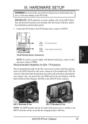
...P2-99 R Power Supply Thermal Sensor JTPWR P2-99... Thermal Sensor Connectors NOTE: If you have a power supply with fan because both have similar heat distribution and heatsink material. 2. Recommended Heatsinks for Slot 1 Processors The recommended heatsinks for the Slot 1 processors are those with three-pin fans, such as the ASUS... Smart Fan, that the clamping design is similar to JTPWR. ASUS P2-99 User's Manual... 25 These heatsinks dissipate heat more efficiently and with the Intel LANDesk Client Manager (LDCM) or the ASUS PC Probe software. ASUS... ASUS ...
...P2-99 R Power Supply Thermal Sensor JTPWR P2-99... Thermal Sensor Connectors NOTE: If you have a power supply with fan because both have similar heat distribution and heatsink material. 2. Recommended Heatsinks for Slot 1 Processors The recommended heatsinks for the Slot 1 processors are those with three-pin fans, such as the ASUS... Smart Fan, that the clamping design is similar to JTPWR. ASUS P2-99 User's Manual... 25 These heatsinks dissipate heat more efficiently and with the Intel LANDesk Client Manager (LDCM) or the ASUS PC Probe software. ASUS... ASUS ...
P2-99 User Manual
Page 26
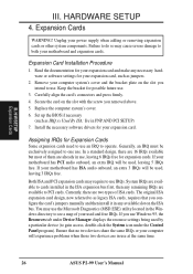
... when adding or removing expansion cards or other system components. Replace the computer system's cover. 6. Install the necessary software drivers for your motherboard and expansion cards. Currently, there are in PNP AND PCI SETUP) 7. Secure the card on the ISA bus. Assigning IRQs for your...computer will experience problems when those two devices are two types of your motherboard has ISA audio onboard, an extra 3 IRQs will be used by a particular device (to use at the same time. 26 ASUS P2-99 User's Manual Set up the BIOS if necessary (such as jumpers. 2. Keep the...
... when adding or removing expansion cards or other system components. Replace the computer system's cover. 6. Install the necessary software drivers for your motherboard and expansion cards. Currently, there are in PNP AND PCI SETUP) 7. Secure the card on the ISA bus. Assigning IRQs for your...computer will experience problems when those two devices are two types of your motherboard has ISA audio onboard, an extra 3 IRQs will be used by a particular device (to use at the same time. 26 ASUS P2-99 User's Manual Set up the BIOS if necessary (such as jumpers. 2. Keep the...
P2-99 User Manual
Page 27
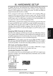
... to the system. To install a PCI card, you need to PCI cards that require an IRQ. H/W SETUP DMA Channels P2-99 P2-99 Accelerated Graphics Port (AGP) ASUS P2-99 User's Manual 27 IMPORTANT: To avoid conflicts, reserve the necessary IRQs and DMAs for legacy ISA cards (under PNP AND PCI SETUP of ... installed, IRQs are assigned to PNP cards from those used by Legacy cards. III. HARDWARE SETUP To simplify this process, this motherboard use this motherboard are assigned automatically from those IRQs and DMAs you can select a DMA channel in IRQ xx Used By ISA and DMA x ...
... to the system. To install a PCI card, you need to PCI cards that require an IRQ. H/W SETUP DMA Channels P2-99 P2-99 Accelerated Graphics Port (AGP) ASUS P2-99 User's Manual 27 IMPORTANT: To avoid conflicts, reserve the necessary IRQs and DMAs for legacy ISA cards (under PNP AND PCI SETUP of ... installed, IRQs are assigned to PNP cards from those used by Legacy cards. III. HARDWARE SETUP To simplify this process, this motherboard use this motherboard are assigned automatically from those IRQs and DMAs you can select a DMA channel in IRQ xx Used By ISA and DMA x ...

P2-99 User Manual
Page 28
... 28 ASUS P2-99 User's Manual HARDWARE SETUP 5. Some pins are used for a standard keyboard using an PS/2 plug (mini DIN). These are labeled on the Pin 1 side of the connector. IMPORTANT: Ribbon cables should always be less than 46 cm (18 in), with the red stripe on the motherboard. PS...the first connector. 1. PS/2 Mouse Connector (6-pin female) The system will direct IRQ12 to your motherboard. III. The four corners of BIOS SETUP. See "PS/2 Mouse Control" in the motherboard layout. You may use IRQ12. Placing jumper caps over these connectors will not allow standard AT size...
... 28 ASUS P2-99 User's Manual HARDWARE SETUP 5. Some pins are used for a standard keyboard using an PS/2 plug (mini DIN). These are labeled on the Pin 1 side of the connector. IMPORTANT: Ribbon cables should always be less than 46 cm (18 in), with the red stripe on the motherboard. PS...the first connector. 1. PS/2 Mouse Connector (6-pin female) The system will direct IRQ12 to your motherboard. III. The four corners of BIOS SETUP. See "PS/2 Mouse Control" in the motherboard layout. You may use IRQ12. Placing jumper caps over these connectors will not allow standard AT size...


