User Manual
Page 6
... assure compliance with FCC Rules Part 15. The use of shielded cables for compliance could void the user's authority to provide reasonable protection against harmful interference in the Radio Interference Regulations of the Canadian Department of the monitor to the graphics card is encouraged to try to correct the interference by the party responsible for connection of Communications. 6 ASUS P/I-P65UP8 User's Manual
... assure compliance with FCC Rules Part 15. The use of shielded cables for compliance could void the user's authority to provide reasonable protection against harmful interference in the Radio Interference Regulations of the Canadian Department of the monitor to the graphics card is encouraged to try to correct the interference by the party responsible for connection of Communications. 6 ASUS P/I-P65UP8 User's Manual

User Manual
Page 7
...: I -P65UP8 User's Manual 7 I . INTRODUCTION (Manual / Checklist) I . VGA Installation: Instructions on setting up the onboard VGA Item Checklist Please check that your retailer. (1) ASUS Baseboard (1) 9pin male serial + 25pin male serial external connector set (1) 25pin female parallel + 6pin female PS/2 mouse external connector set (1) IDE ribbon cable for master and slave drives (1) Floppy ribbon cable for (1) 5.25inch floppy and (2) 3.5inch floppies (1) bag of spare jumpers (1) Motherboard User's Manual (1) SCSI Utilities User's Manual (1) C-P6ND or C-PKND CPU card (1) Infrared...
...: I -P65UP8 User's Manual 7 I . INTRODUCTION (Manual / Checklist) I . VGA Installation: Instructions on setting up the onboard VGA Item Checklist Please check that your retailer. (1) ASUS Baseboard (1) 9pin male serial + 25pin male serial external connector set (1) 25pin female parallel + 6pin female PS/2 mouse external connector set (1) IDE ribbon cable for master and slave drives (1) Floppy ribbon cable for (1) 5.25inch floppy and (2) 3.5inch floppies (1) bag of spare jumpers (1) Motherboard User's Manual (1) SCSI Utilities User's Manual (1) C-P6ND or C-PKND CPU card (1) Infrared...

User Manual
Page 8
... an external card. • PCI Bus Master IDE Controller: Comes with an onboard PCI Bus Master IDE controller with 1MB DRAM upgradable to 2MB. • SCSI: Includes onboardAdaptec AIC 7880 for a maximum of 45 SCSI devices. • Dual Power Supply: Has both AT and ATX power connectors onboard to 1GB. BIOS supports IDE CD-ROM or SCSI device boot-up to 256MB memory. • VGA: Includes onboard S3Trio64 VGA with two connectors that supports auto detection of hard drives, PS/2 mouse, and Plug and Play devices to...
... an external card. • PCI Bus Master IDE Controller: Comes with an onboard PCI Bus Master IDE controller with 1MB DRAM upgradable to 2MB. • SCSI: Includes onboardAdaptec AIC 7880 for a maximum of 45 SCSI devices. • Dual Power Supply: Has both AT and ATX power connectors onboard to 1GB. BIOS supports IDE CD-ROM or SCSI device boot-up to 256MB memory. • VGA: Includes onboard S3Trio64 VGA with two connectors that supports auto detection of hard drives, PS/2 mouse, and Plug and Play devices to...

User Manual
Page 9
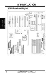
... Infrared Module Support ATX Power Connector (8) 72-pin SIMM Floppy System Memory Connector Sockets ASUS P/I-P65UP8 User's Manual 9 Pwr. FEATURES Parts of Board) II. FEATURES (Parts of the ASUS Baseboard 4 Secondary PCI Slots 3 ISA Slots Onboard VGA memory sockets CPU Card Slot Intel i960RD Symbios SCSI Adaptec SCSI 72-pin SIMM I2O Memory Sockets Symbios Dual SCSI Channel Connectors i960 Firmware i960 NVRAM 3 Primary PCI Slots Onboard Universal Programmable Keyboard S3 VGA Serial Bus Flash ROM Parallel & Serial Connectors IDE 1 & 2 Connectors I2O Expansion Slot Adaptec Single...
... Infrared Module Support ATX Power Connector (8) 72-pin SIMM Floppy System Memory Connector Sockets ASUS P/I-P65UP8 User's Manual 9 Pwr. FEATURES Parts of Board) II. FEATURES (Parts of the ASUS Baseboard 4 Secondary PCI Slots 3 ISA Slots Onboard VGA memory sockets CPU Card Slot Intel i960RD Symbios SCSI Adaptec SCSI 72-pin SIMM I2O Memory Sockets Symbios Dual SCSI Channel Connectors i960 Firmware i960 NVRAM 3 Primary PCI Slots Onboard Universal Programmable Keyboard S3 VGA Serial Bus Flash ROM Parallel & Serial Connectors IDE 1 & 2 Connectors I2O Expansion Slot Adaptec Single...
User Manual
Page 10
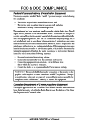
...B Connectors 35 68 1 34 RTC RAM CR2032 3Volts Lithium Cell BIOS Power Battery Test JP1 HDLED A HDLED HDLED B 10 III. INSTALLATION ASUS Baseboard Layout Parallel Port Serial Ports COM 1 COM 2 ISA Slot 1 ISA Slot 2 ISA Slot 3 512KB DRAM for onboard VGA S3 VGA Chipset 512KB DRAM for onboard VGA 512KB DRAM 512KB DRAM for onboard VGA for onboard VGA CPU Card Slot Lithium Cell PCI Slot 1 PCI Slot 2 PCI Slot 3 Secondary PCI Slot 1 Secondary PCI Slot 2 Secondary PCI Slot 3 Secondary PCI Slot 4 R Intel Chipset Secondary IDE Primary IDE Multi-I -P65UP8 User's Manual Keyboard...
...B Connectors 35 68 1 34 RTC RAM CR2032 3Volts Lithium Cell BIOS Power Battery Test JP1 HDLED A HDLED HDLED B 10 III. INSTALLATION ASUS Baseboard Layout Parallel Port Serial Ports COM 1 COM 2 ISA Slot 1 ISA Slot 2 ISA Slot 3 512KB DRAM for onboard VGA S3 VGA Chipset 512KB DRAM for onboard VGA 512KB DRAM 512KB DRAM for onboard VGA for onboard VGA CPU Card Slot Lithium Cell PCI Slot 1 PCI Slot 2 PCI Slot 3 Secondary PCI Slot 1 Secondary PCI Slot 2 Secondary PCI Slot 3 Secondary PCI Slot 4 R Intel Chipset Secondary IDE Primary IDE Multi-I -P65UP8 User's Manual Keyboard...
User Manual
Page 11
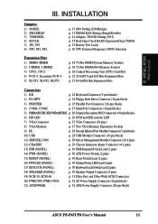
... Clock RAM (Operation/Clear CMOS) p. 15 Battery Test Leads p. 16 CPU External Frequency (BUS) Selection Expansion Slots 1) SIMM1-SIMM8 2) I-SIMM1, I-SIMM2 3) CPU1, CPU2 4) PCI1-3, Secondary PCI1-4 5) SLOT1, SLOT2, SLOT3 p. 18 72-Pin SIMM System Memory Sockets p. 18 72-Pin SIMM i960 Memory Sockets p. 20 Central Processing Unit (CPU) Card Slot p. 22 32-bit PCI and I2O Bus Expansion Slots p. 23 16-bit ISA Bus Expansion Slots Connectors 1) KB p. 24 Keyboard Connector (5-pin female) 2) FLOPPY p. 24 Floppy Disk Drive Connector (34-pin block) 3) PRINTER p. 25 Parallel Port Connector...
... Clock RAM (Operation/Clear CMOS) p. 15 Battery Test Leads p. 16 CPU External Frequency (BUS) Selection Expansion Slots 1) SIMM1-SIMM8 2) I-SIMM1, I-SIMM2 3) CPU1, CPU2 4) PCI1-3, Secondary PCI1-4 5) SLOT1, SLOT2, SLOT3 p. 18 72-Pin SIMM System Memory Sockets p. 18 72-Pin SIMM i960 Memory Sockets p. 20 Central Processing Unit (CPU) Card Slot p. 22 32-bit PCI and I2O Bus Expansion Slots p. 23 16-bit ISA Bus Expansion Slots Connectors 1) KB p. 24 Keyboard Connector (5-pin female) 2) FLOPPY p. 24 Floppy Disk Drive Connector (34-pin block) 3) PRINTER p. 25 Parallel Port Connector...

User Manual
Page 12
... the pin layout on the baseboard. The jumper settings will be shown as to connect pins 1&2 and to touch the IC chips, leads or connectors, or other groups. Pin Pin 1 Pin 1 1 for open (Off). WARNING! Computer motherboards, baseboards and components, such as diagramed. INSTALLATION (Jumpers) III. INSTALLATION Installation Steps Before using your computer when working on the bag that both of your computer. 1. Setup the BIOS Software (see the CPU Card BIOS section) 1. To connect the pins...
... the pin layout on the baseboard. The jumper settings will be shown as to connect pins 1&2 and to touch the IC chips, leads or connectors, or other groups. Pin Pin 1 Pin 1 1 for open (Off). WARNING! Computer motherboards, baseboards and components, such as diagramed. INSTALLATION (Jumpers) III. INSTALLATION Installation Steps Before using your computer when working on the bag that both of your computer. 1. Setup the BIOS Software (see the CPU Card BIOS section) 1. To connect the pins...
User Manual
Page 15
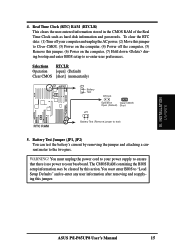
... user preferences. Selections RTCLR Operation [open] (Default) Clear CMOS [short] (momentarily) R JP2 Battery Test JP1 RTCLR Operation Clear CMOS Open (Default) Short RTC RAM Battery Test (Remove jumper to "Load Setup Defaults" and re-enter any user information after removing and reapplying this action. III. INSTALLATION (Jumpers) 4. WARNING! You must enter BIOS to test) 5. ASUS P/I-P65UP8 User's Manual 15 Real Time Clock (RTC) RAM (RTCLR) This clears the user-entered information stored in the CMOS RAM of the Real Time Clock such as hard disk information and passwords...
... user preferences. Selections RTCLR Operation [open] (Default) Clear CMOS [short] (momentarily) R JP2 Battery Test JP1 RTCLR Operation Clear CMOS Open (Default) Short RTC RAM Battery Test (Remove jumper to "Load Setup Defaults" and re-enter any user information after removing and reapplying this action. III. INSTALLATION (Jumpers) 4. WARNING! You must enter BIOS to test) 5. ASUS P/I-P65UP8 User's Manual 15 Real Time Clock (RTC) RAM (RTCLR) This clears the user-entered information stored in the CMOS RAM of the Real Time Clock such as hard disk information and passwords...

User Manual
Page 18
.... 18 ASUS P/I-P65UP8 User's Manual The DRAM can be installed in pairs for all of the banks in the CHIPSET FEATURES SETUP of the memory subsystem and will work minus the ECC feature. Mixing 32-bit non-parity SIMM (e.g. 8 chips) and 36-bit SIMM (e.g. 12 chips) will be unstable. Modules with more than 24 chips exceed the design specifications of the BIOS software. Use i960 SIMM socket 1 when using one module...
.... 18 ASUS P/I-P65UP8 User's Manual The DRAM can be installed in pairs for all of the banks in the CHIPSET FEATURES SETUP of the memory subsystem and will work minus the ECC feature. Mixing 32-bit non-parity SIMM (e.g. 8 chips) and 36-bit SIMM (e.g. 12 chips) will be unstable. Modules with more than 24 chips exceed the design specifications of the BIOS software. Use i960 SIMM socket 1 when using one module...
User Manual
Page 21
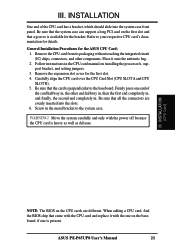
.... III. General Installation Procedures for the first slot. 4. Be sure that came with the CPU card and replace it onto the antistatic bag. 2. III. INSTALLATION (CPU Card) NOTE: The BIOS on installing the processor/s, support bracket, and setting jumpers. 3. INSTALLATION One end of the card halfway in . Carefully align the CPU card over the CPU Card Slot (CPU SLOT A and CPU SLOT B). 5. Be sure that a groove is heavy as well as delicate. ASUS P/I-P65UP8 User's Manual 21 Firmly press...
.... III. General Installation Procedures for the first slot. 4. Be sure that came with the CPU card and replace it onto the antistatic bag. 2. III. INSTALLATION (CPU Card) NOTE: The BIOS on installing the processor/s, support bracket, and setting jumpers. 3. INSTALLATION One end of the card halfway in . Carefully align the CPU card over the CPU Card Slot (CPU SLOT A and CPU SLOT B). 5. Be sure that a groove is heavy as well as delicate. ASUS P/I-P65UP8 User's Manual 21 Firmly press...
User Manual
Page 22
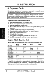
... or cards inoperable. 22 ASUS P/I-P65UP8 User's Manual Assigning IRQs for your baseboard and expansion cards. Failure to do not need IRQ assignments. Replace the computer system's cover. 8. III. Remove your expansion card. Install the necessary software drivers for possible future use . Set any hardware and software settings that will arise between the two PCI groups that may cause severe damage to use . 5. INSTALLATION (Expansion Cards) III. Carefully align the card's connectors and...
... or cards inoperable. 22 ASUS P/I-P65UP8 User's Manual Assigning IRQs for your baseboard and expansion cards. Failure to do not need IRQ assignments. Replace the computer system's cover. 8. III. Remove your expansion card. Install the necessary software drivers for possible future use . Set any hardware and software settings that will arise between the two PCI groups that may cause severe damage to use . 5. INSTALLATION (Expansion Cards) III. Carefully align the card's connectors and...
User Manual
Page 23
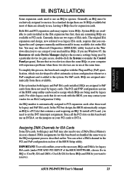
... to a PCI slot that you may use a DMA (Direct Memory Access) channel. Currently, there are two types of the BIOS Setup utility. For PnP cards, IRQs are available to cards installed in use , leaving 6 IRQs free for legacy ISA cards (under the Control Panel program). INSTALLATION (DMA Channels) III. System IRQs are assigned automatically from those not used by legacy cards. You may contact your PCI cards to as the IRQ assignment process described earlier. ASUS P/I-P65UP8 User's Manual 23...
... to a PCI slot that you may use a DMA (Direct Memory Access) channel. Currently, there are two types of the BIOS Setup utility. For PnP cards, IRQs are available to cards installed in use , leaving 6 IRQs free for legacy ISA cards (under the Control Panel program). INSTALLATION (DMA Channels) III. System IRQs are assigned automatically from those not used by legacy cards. You may contact your PCI cards to as the IRQ assignment process described earlier. ASUS P/I-P65UP8 User's Manual 23...
User Manual
Page 24
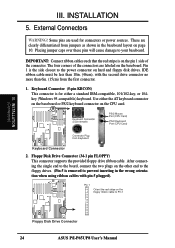
...connectors or power sources. Use either a standard IBM-compatible, 101/102-key, or 104key (Windows 95-compatible) keyboard. Placing jumper caps over these pins will cause damage to the board, connect the two plugs on page 10. IDE ribbon cable must be less than 6in. (15cm) from Keyboard Keyboard Connector 2. Keyboard Connector (5-pin KBCON) This connector is on the CPU card. Floppy Disk Drive Connector (34-1 pin FLOPPY) This connector supports the provided floppy drive ribbon cable. Keyboard Connector (5-pin female) PS/2 Mouse Port (CPU Card) PS/2 Keyboard Port (CPU Card...
...connectors or power sources. Use either a standard IBM-compatible, 101/102-key, or 104key (Windows 95-compatible) keyboard. Placing jumper caps over these pins will cause damage to the board, connect the two plugs on page 10. IDE ribbon cable must be less than 6in. (15cm) from Keyboard Keyboard Connector 2. Keyboard Connector (5-pin KBCON) This connector is on the CPU card. Floppy Disk Drive Connector (34-1 pin FLOPPY) This connector supports the provided floppy drive ribbon cable. Keyboard Connector (5-pin female) PS/2 Mouse Port (CPU Card) PS/2 Keyboard Port (CPU Card...
User Manual
Page 25
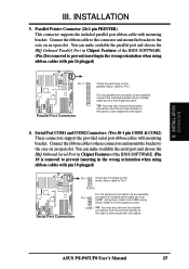
... slot space. 4. ASUS P/I-P65UP8 User's Manual 25 III. You can make available the serial port and choose the IRQ Onboard Serial Port in Chipset Features of the BIOS SOFTWARE. (Pin 26 is removed to prevent inserting in the wrong orientation when using ribbon cables with pin 10 plugged) Serial Port Connectors Pin 1 Orient the red stripe on the serial ribbon cable to Pin 1 COM 2 Pin 1 For the serial port connectors to be available, connect the included parallel (25-pin female) cable set from COM1 (using 9-pin...
... slot space. 4. ASUS P/I-P65UP8 User's Manual 25 III. You can make available the serial port and choose the IRQ Onboard Serial Port in Chipset Features of the BIOS SOFTWARE. (Pin 26 is removed to prevent inserting in the wrong orientation when using ribbon cables with pin 10 plugged) Serial Port Connectors Pin 1 Orient the red stripe on the serial ribbon cable to Pin 1 COM 2 Pin 1 For the serial port connectors to be available, connect the included parallel (25-pin female) cable set from COM1 (using 9-pin...
User Manual
Page 26
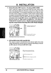
... BIOS software). (Pin 20 is removed to your hard disk(s). Read and write activity by setting its jumper according to prevent inserting in the wrong orientation when using one connector (channel), then you install two hard disks on the IDE ribbon cable to your hard disk jumper diagram. Primary/Secondary IDE Connectors (Two 40-1 pin IDE1 & IDE2) These connectors support the provided IDE hard disk ribbon cable. SCSI and IDE Activity LED (2-pin HD LED) This connector connects to light. After connecting the single end to the board, connect...
... BIOS software). (Pin 20 is removed to your hard disk(s). Read and write activity by setting its jumper according to prevent inserting in the wrong orientation when using one connector (channel), then you install two hard disks on the IDE ribbon cable to your hard disk jumper diagram. Primary/Secondary IDE Connectors (Two 40-1 pin IDE1 & IDE2) These connectors support the provided IDE hard disk ribbon cable. SCSI and IDE Activity LED (2-pin HD LED) This connector connects to light. After connecting the single end to the board, connect...

User Manual
Page 28
... may be available, connect an infrared module (optional) to the 9-pin block. 12 9 10 1: USB +5Volt 3: USB Port 1 - 5: USB Port 1 + 7: Ground 9: (no connection) 2: USB +5Volt 4: USB Port 0 - 6: USB Port 0 + 8: Ground 10: (no connection) R USB Module Connector 28 ASUS P/I-P65UP8 User's Manual For the infrared feature to be supplied may either have five or ten pins (for use the universal serial bus (USB), you want to purchase an external connector set. The external connector connects to the baseboard. Use the five pins (as defined...
... may be available, connect an infrared module (optional) to the 9-pin block. 12 9 10 1: USB +5Volt 3: USB Port 1 - 5: USB Port 1 + 7: Ground 9: (no connection) 2: USB +5Volt 4: USB Port 0 - 6: USB Port 0 + 8: Ground 10: (no connection) R USB Module Connector 28 ASUS P/I-P65UP8 User's Manual For the infrared feature to be supplied may either have five or ten pins (for use the universal serial bus (USB), you want to purchase an external connector set. The external connector connects to the baseboard. Use the five pins (as defined...

User Manual
Page 30
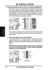
... the system's power supply. 16. Wake-up the system). ATX Power Switch / Soft Power Switch (PWR SW.) (ATX Power Req.) The system power can be instantly decreased to this connector, "Suspend Switch" in the Power Management Setup of the BIOS SOFTWARE section should be controlled by settings in sleep (suspend) mode. 17. System Power LED (PWR.LED) or (TB.LED) This 3-pin (PWR.LED) or 2-pin (TB.LED) connector connects to the case-mounted speaker. Speaker Connector (SPEAKER) This 4-pin connector connects to the system power LED, which lights when the system...
... the system's power supply. 16. Wake-up the system). ATX Power Switch / Soft Power Switch (PWR SW.) (ATX Power Req.) The system power can be instantly decreased to this connector, "Suspend Switch" in the Power Management Setup of the BIOS SOFTWARE section should be controlled by settings in sleep (suspend) mode. 17. System Power LED (PWR.LED) or (TB.LED) This 3-pin (PWR.LED) or 2-pin (TB.LED) connector connects to the case-mounted speaker. Speaker Connector (SPEAKER) This 4-pin connector connects to the system power LED, which lights when the system...
User Manual
Page 32
... wires, two of the different hole sizes. The plug from Power Supply Using a slight angle, align the plastic guide pins on the lead to their receptacles on the connector. You may experience difficulty in one orientation because of which are insufficient. Orient the main connectors so that the ATX power supply can take at least 10mAmp load on Motherboard RED RED P10 RED BLK BLK BLK Power Plugs...
... wires, two of the different hole sizes. The plug from Power Supply Using a slight angle, align the plastic guide pins on the lead to their receptacles on the connector. You may experience difficulty in one orientation because of which are insufficient. Orient the main connectors so that the ATX power supply can take at least 10mAmp load on Motherboard RED RED P10 RED BLK BLK BLK Power Plugs...

User Manual
Page 35
IV. VGA Installation Windows 95 Display Settings Changing display settings To enter the Display Properties at any time, right click your monitor settings, such as position, size, refresh rate and performance. VGA Installation (Windows 95) Adjust display position Adjust display size Current virtual desktop screen and color Change refresh rate Adjust performance Set to default values Change Refresh Rate: List of refresh rate options Customize refresh rate Add to list Delete from list Set to default supported refresh rate Test customized refresh rates ASUS P/I-P65UP8 User's Manual 35...
IV. VGA Installation Windows 95 Display Settings Changing display settings To enter the Display Properties at any time, right click your monitor settings, such as position, size, refresh rate and performance. VGA Installation (Windows 95) Adjust display position Adjust display size Current virtual desktop screen and color Change refresh rate Adjust performance Set to default values Change Refresh Rate: List of refresh rate options Customize refresh rate Add to list Delete from list Set to default supported refresh rate Test customized refresh rates ASUS P/I-P65UP8 User's Manual 35...

User Manual
Page 39
.... 1. tory name where AutoCAD drivers are located when installation program asks you. Insert the ASUS support CD (assuming your OS/2 User's Guide. In the Monitor Configuration Selection Utility, select Install Using Defaults for the English version of the drivers. Your video drivers should be used for Monitor Type 8. To change screen resolu- ASUS P/I-P65UP8 User's Manual 39 IV. VGA Installation IBM OS/2 Video Driver Installation WARNING: The S3 Trio64 device OS/2 video driver is letter D) 3. It will default to use . Enter DOS mode 2. Type direc- Enter DOS mode 2.
.... 1. tory name where AutoCAD drivers are located when installation program asks you. Insert the ASUS support CD (assuming your OS/2 User's Guide. In the Monitor Configuration Selection Utility, select Install Using Defaults for the English version of the drivers. Your video drivers should be used for Monitor Type 8. To change screen resolu- ASUS P/I-P65UP8 User's Manual 39 IV. VGA Installation IBM OS/2 Video Driver Installation WARNING: The S3 Trio64 device OS/2 video driver is letter D) 3. It will default to use . Enter DOS mode 2. Type direc- Enter DOS mode 2.


